|
|
This chapter describes the procedures to make all external cable connections to the Catalyst 5000 series switch at your site. It includes the procedures for connecting a redundant AC-input power supply and applying power to the Catalyst 5000 series switch.
This section describes the basic network connections---Ethernet, FDDI, CDDI, and ATM--- that you will make to the switch. Using the Port Configuration Worksheet will help you to make connections and later configure each interface without having to access the rear of the chassis to check port addresses. See the section "Using the Port Configuration Worksheets" in the appendix "Configuration Worksheets."
The following guidelines will assist you in properly connecting the external network cables to your switch.
![]()
If the switch fails to operate in the manner specified in the publication Catalyst 5000 Series Configuration Guide and Command Reference, refer to the chapter "Confirming the Installation" in this guide to help isolate the problem and then notify a customer service representative.
The sections that follow provide illustrations of the connections between the switch interface ports and your network(s). Interface cables and equipment, such as Ethernet transceivers and interface cables, should already be available and in place. If they are not, refer to the following section "Viewing Module Connections" for descriptions of the equipment you need for each interface type to complete the connection to your network.
Figure 4-2 and Figure 4-2 show examples of Catalyst 5000 Ethernet, Fast Ethernet, and fiber optic module connectors. For descriptions of connection equipment and connector locks, refer to the section "Setting Up Ethernet Connection Equipment" in the chapter "Installation Overview."
Figure 4-1 : Supervisor Engine Module Port Connections
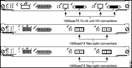
Figure 4-2 : Module Port Connections
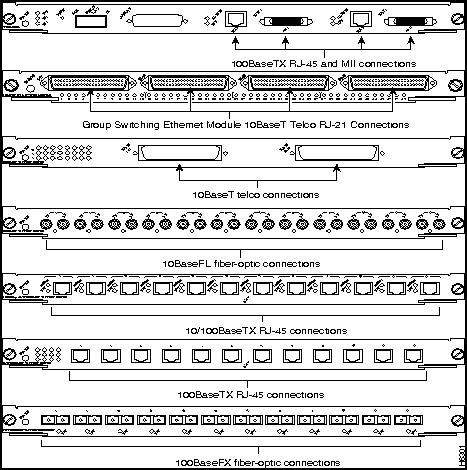
On each 10BaseT, 100BaseTX, or 10/100BaseTX switching module port, attach the cable connector and secure the cable in the port, and for the side connector use a tie wrap to provide strain relief. Most Ethernet connections do not require a transceiver on the interface cable. 100BaseTX Fast Ethernet connections to the MII connector on the supervisor engine module require a Fast Ethernet transceiver.
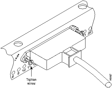
T o complete the 10BaseT port connection, tighten the screws and secure the Ethernet RJ-21 Telco interface 90 degree connector with a tie wrap as shown in Figure 4-3 and Figure 4-4. Figure 4-5 and Figure 4-6 show the connector placement for the Group Switching Ethernet module Telco cable.
Figure 4-3 : Securing the Ethernet Switching Module (10BaseT 24 Port) Tie Wrap
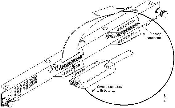
Figure 4-4 : Ethernet Switching Module (10BaseT 24 Port) Telco Cable Attachment
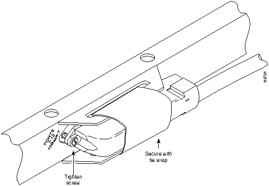
Figure 4-5 : Group Switching Ethernet Module (10BaseT 48Port) Connector Placement
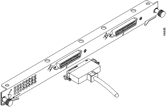
Figure 4-6 : Group Switching Ethernet Module (10BaseT 48 Port) Telco Cable Attachment
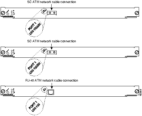
All ATM interfaces are full duplex. You must use the appropriate ATM interface cable to connect the ATM LAN emulation module with an external ATM network.
The ATM LAN emulation module provides an interface to ATM switching fabrics for transmitting and receiving data at up to 155 Mbps bidirectionally; the actual data rate is determined by the physical layer interface module (PLIM).
The ATM LAN emulation module can support interfaces that connect to the following physical layers:
Connect the ATM interface cables as shown in Figure 4-7. For detailed descriptions of ATM cabling requirements, refer to the section "Limiting Connection Distances" and the section "Making ATM Connections" in the chapter "Installation Overview."
The FDDI/CDDI UTP and fiber-optic cables connect directly to the CDDI or FDDI module ports. CDDI and FDDI use one integrated transmit/receive cable for each physical interface (one for PHY A and one for PHY B). You will need one CDDI or FDDI cable for a single attachment connection, and two cables for a dual attachment connection. Figure 4-10 and Figure 4-11 show dual attachment connections that use both fiber and copper (UTP) and illustrate the types of connections used for CDDI and FDDI. For cable and connector descriptions, refer to the section "Setting Up CDDI/FDDI Connection Equipment" in the chapter "Installation Overview."
This section also provides instructions for connecting an optical bypass switch to a dual attachment FDDI network connection. Because the method of connecting optical bypass switches varies with different manufacturer's models, refer to the documentation for your particular bypass switch for correct connection instructions. If you are installing an optical bypass switch, proceed to the section "Installing an Optical Bypass Switch" later in this chapter.
Making Single Attachment Connections
The CDDI and FDDI modules that are connected as a single attachment station (SAS) are typically connected to the ring through a concentrator. The CDDI and FDDI modules receive and transmit the signal through the same physical interface, usually PHY A. Depending on whether you are connecting to a CDDI network or single-mode or multimode FDDI fiber network, connect the CDDI or FDDI modules as follows:
If you are connecting other CDDI or FDDI modules as dual attachment stations (DASs), proceed to the section "Making Dual Attachment Connections."
Figure 4-8 : Single Attachment Station, Multimode FDDI Network Connections
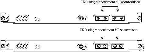
Figure 4-9 : SIngle Attachment Station, CDDI Network Connections

Making Dual Attachment Connections
CDDI and FDDI modules that are connected as DAS connect to both the primary and secondary rings. The signal for each ring is received on one physical interface (PHY A or PHY B) and transmitted from the other. The standard connection scheme (see Figure 4-10 and Figure 4-11) for a DAS dictates that the primary ring signal comes into the CDDI or FDDI module on the PHY A receive port and returns to the primary ring from the PHY B transmit port. The secondary ring signal comes into the CDDI or FDDI module on the PHY B receive port and returns to the secondary ring from the PHY A transmit port. Failure to observe this relationship will prevent the CDDI or FDDI interface from initializing. Figure 4-10 and Figure 4-11 show the CDDI and FDDI connections for dual attachment and both multimode and single-mode fiber.
Connect the CDDI or FDDI module as follows. Each of the integrated transmit/receive multimode interface cables attaches to both the primary and secondary ring; each one receives the signal from one ring and transmits to the other ring. (See Figure 4-10 and Figure 4-11.)
Figure 4-10 : FDDI Module Dual Attachment Network Connections
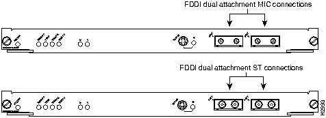
Figure 4-11 : CDDI Module Dual Attachment Network Connections

To help avoid confusion, use the receive label on the cable connector as a key and connect the cables to the FDDI module ports as follows:
If you are connecting an optical bypass switch, proceed to the next section "Installing an Optical Bypass Switch."
Installing an Optical Bypass Switch
An optical bypass switch is a device installed between the ring and the station that provides additional fault tolerance to the network. If an FDDI module that is connected to a bypass switch fails or shuts down, the bypass switch activates automatically and allows the light signal to pass directly through it, bypassing the FDDI module completely. A port for connecting an optical bypass switch is provided on the multimode/multimode FDDI module only. (See Figure 4-12.)
Figure 4-12 : FDDI Module Connection with Optical Bypass

The optical bypass control port on the FDDI module is a six-pin mini-DIN receptacle. Some optical bypass switches use DIN connectors, and some use a mini-DIN.
Following are general instructions for connecting an optical bypass switch to the FDDI module; however, your particular bypass switch may require a different connection scheme. Use these steps as a general guideline, but refer to the instructions provided by the manufacturer of the switch for specific connection requirements.
Using Serial Connections and a Console Terminal
The supervisor engine module console port is a DCE DB-25 receptacle, which supports a DCE EIA/TIA-232 interface type and mode. For descriptions and illustrations of each connector type, refer to the section "Configuring EIA/TIA-232 Connections" in the chapter "Installation Overview." For cable pinouts, refer to the appendix "Cabling Specifications."
When connecting a serial device, consider the cable as an extension of the switch for an external connection; therefore, use null-modem cable to connect the switch to a remote DCE device such as a modem or data service unit (DSU), and use a straight-through cable to connect the switch to a DTE device such as a terminal or PC.
Use the console port to connect a data terminal, which you will need to configure and communicate with your system. The port is located on the supervisor engine module faceplate and is labelled CONSOLE, as shown in Figure 4-13.
Figure 4-13 : Serial Port Adapter Cable (Console Port) Connections
Before connecting the console port, check your terminal's documentation to determine the baud rate. The baud rate of the terminal must match the default baud rate (9600 baud) of the terminal you will be using. Set up the terminal as follows:
After connecting a data terminal to the console port, follow the steps in the next section, "Connecting Power."
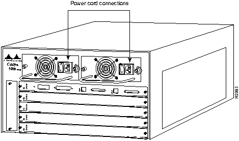
This section describes the procedures to apply power to the Catalyst 5000 series switch at your site. It includes instructions for connecting a redundant AC-input power supply.
Connect an AC-input power supply, as follows:
Figure 4-14 : Power Cord Connections
When all interfaces are connected, perform a final check of all connections, then take the following steps to check the components and power up the system:
During the boot process, the status LED on all interfaces is orange. Some LEDs may go on and remain on or go out and go on again for a short time. Some LEDs, such as the link LED, will stay on during the entire boot process. If an interface is already configured, the LEDs may go on steadily as they detect traffic on the line. Wait until the system boot is complete before attempting to verify the switching module LED indications.
When the system boot is complete (it takes a few seconds), the supervisor engine module begins to initialize the switching modules. During this initialization, the LEDs on each switching module behave differently (most flash on and off). The status LED on each switching module goes on when initialization has been completed, and the console screen displays a script and system banner similar to the following:
Many of the switching module LEDs will not go on until you have configured the interfaces. In order to verify correct operation of each interface, complete the first-time startup procedures and configuration, then refer to the LED descriptions in the chapter "Confirming the Installation" to check the status of the interfaces.
Your installation is now complete. Refer to the chapter "Configuring the Software" or refer to the publication Catalyst 5000 Series Configuration Guide and Command Reference for additional information if needed.
Copyright 1988-1996 © Cisco Systems Inc.

ATE0
ATS0=1

Catalyst 5000 Power Up Diagnostics

Init NVRAM Log
LED Test
ROM CHKSUM
DUAL PORT RAM r/w
RAM r/w
RAM address test
Byte/Word Enable test
RAM r/w 55aa
RAM r/w aa55
EARL test

BOOTROM Version 1.4, Dated Dec  5 1995 16:49:40
BOOT date: 00/00/00 BOOT time: 03:18:57
SIMM RAM address test
SIMM Ram r/w 55aa
SIMM Ram r/w aa55
Start to Uncompress Image ...
IP address for Catalyst not configured
BOOTP will commence after the ports are online
Ports are coming online ...
Cisco Systems Console
Enter password:
Thu Mar 21 1996  03:20:41    Module 1 is online

Enter Password:
Thu Mar 21 1996  03:20:41    Module 2 is online

Enter Password:

Sending RARP request with address 00:40:0b:6c:2b:ff
Sending bootp request with address: 00:40:0b:6c:2b:ff
Sending RARP request with address 00:40:0b:6c:2b:ff
Sending bootp request with address: 00:40:0b:6c:2b:ff
Sending RARP request with address 00:40:0b:6c:2b:ff
Sending bootp request with address: 00:40:0b:6c:2b:ff
Sending RARP request with address 00:40:0b:6c:2b:ff
Sending bootp request with address: 00:40:0b:6c:2b:ff
Sending RARP request with address 00:40:0b:6c:2b:ff
Sending bootp request with address: 00:40:0b:6c:2b:ff
Sending RARP request with address 00:40:0b:6c:2b:ff
Sending bootp request with address: 00:40:0b:6c:2b:ff
Sending RARP request with address 00:40:0b:6c:2b:ff
Sending bootp request with address: 00:40:0b:6c:2b:ff
Sending RARP request with address 00:40:0b:6c:2b:ff
Sending bootp request with address: 00:40:0b:6c:2b:ff
Sending RARP request with address 00:40:0b:6c:2b:ff
Sending bootp request with address: 00:40:0b:6c:2b:ff
Sending RARP request with address 00:40:0b:6c:2b:ff
Sending bootp request with address: 00:40:0b:6c:2b:ff
Console>
![]()
![]()
![]()
![]()
![]()
![]()
![]()
![]()