|
|
This appendix includes instructions, examples, and blank worksheets used for the initial installation and subsequent maintenance of the Catalyst 5000 series switch. Following is a list of worksheets:
Obtain copies of the worksheets shown in Figure B-1, Figure B-2, Figure B-3, Figure B-22, Figure B-23, Figure B-24, Figure B-25, Figure B-26, and Figure B-27 before continuing so that as you proceed through the following descriptions, you can record your information on the copies.
Each of the forms should be completed and kept in a safe place for future reference in the permanent site record.
The worksheets are described in the following sections.
Switch Installation Checklists
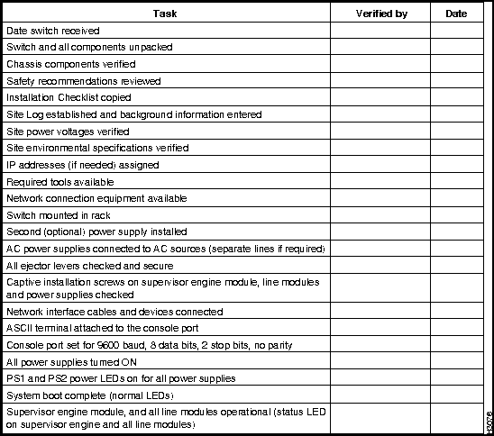
The Switch Installation Checklist is used to confirm that you have all of the information needed to install and configure the Catalyst 5000 series switch and that all of the components are installed and operating correctly.
Before starting the installation, copy the Switch Installation Checklist shown in Figure B-1. Each task in the Switch Installation Checklist should be verified by the person performing the installation and then dated for the permanent site record.
Every task in the Switch Installation Checklist is listed in the index and described in detail in previous chapters of this document.
Figure B-1 : Switch Installation Checklist
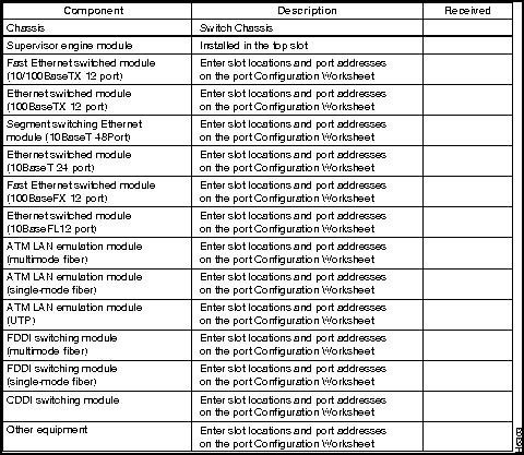
The Switch Accessories Box Components Checklist in Figure B-2 and the Switch System Components Checklist in Figure B-3 list all of the hardware and documentation items needed to complete this installation. Before starting the installation process, the person unpacking the equipment should verify each component in the two checklists. Every component in the Switch System Components Checklist is listed in the index and described in this document.
Figure B-2 : Switch Accessories Box Components Checklist
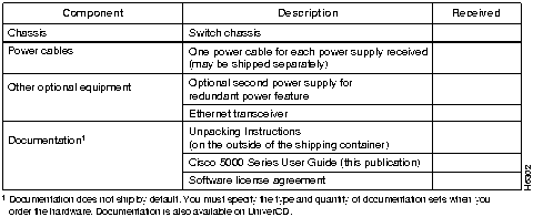
Figure B-3 : Switch System Components Checklist
The Port Configuration Worksheet is used during the software configuration process.
Each heading in the Port Configuration Worksheet should be completed by the person configuring the switch and kept for the permanent site record.
Every component in the Port Configuration Checklist is listed in the index and described in detail in previous chapters of this document.
Using the Port Configuration Worksheets
This section contains two sample Catalyst series switch configurations and the corresponding port configuration forms.
Single Switch Configuration Example
The single Catalyst 5000 series switch example is shown in Figure B-4, and the completed Port Configuration Worksheets are shown in Figure B-5 through Figure B-9.
This first configuration shows a very simple case which includes the following elements:
For simplicity, Figure B-4 shows all devices on each module as either full or half duplex. Each port on each module can be independently configured for either full or half duplex operation. This is illustrated in the following example.
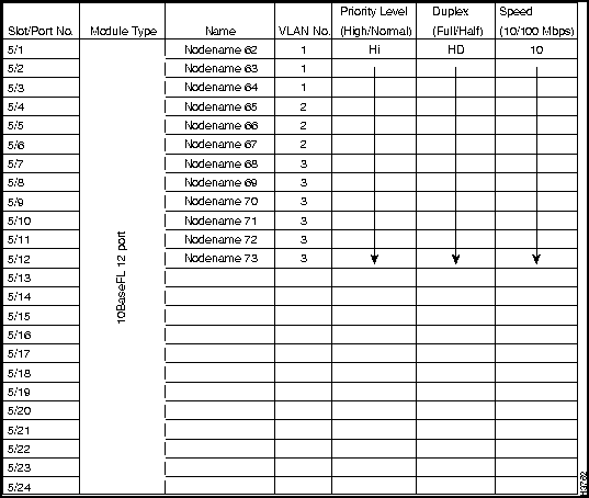
For simplicity, Figure B-5 shows a direct correlation between port speed and traffic priority; the two parameters are completely independent of one another.
Figure B-4 : Single Catalyst 5000 Series Switch Configuration
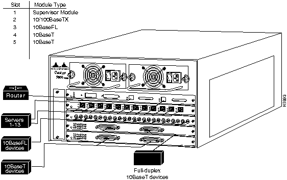
Figure B-5 : Port Configuration Worksheet for the Supervisor Engine Module---Single Switch
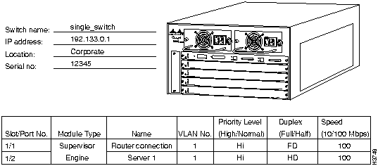
Figure B-6 : Port Configuration Worksheet Slot Number 2---Single Switch
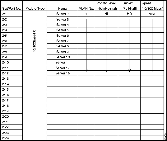
Figure B-7 : Port Configuration Worksheet Slot Number 3---Single Switch
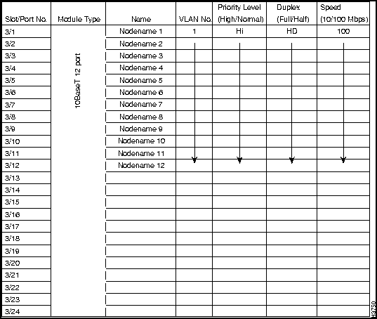
Figure B-8 : Port Configuration Worksheet Slot Number 4---Single Switch
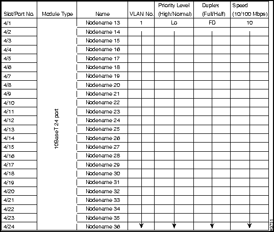
Figure B-9 : Port Configuration Worksheet Slot Number 5---Single Switch
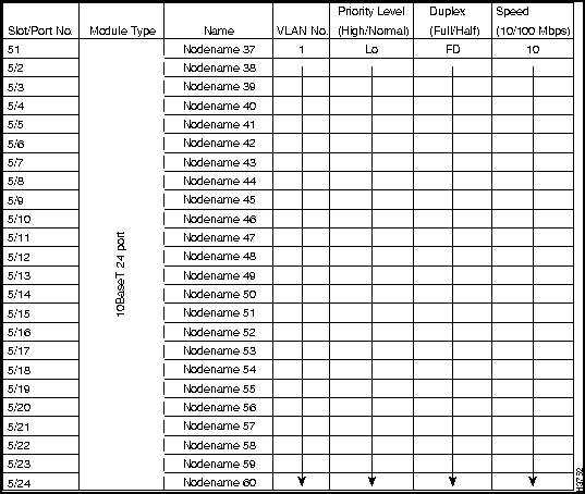
Dual Switch Configuration Example
The more complex dual Catalyst 5000 series switch examples are shown in Figure B-10 and Figure B-11, and the completed Port Configuration Worksheets are shown in Figure B-12 through Figure B-21.
This configuration shows a more complex example using ISL and VLAN connections, which includes the following elements:
Figure B-10 shows a direct correlation between port speed and traffic priority, the two parameters that are completely independent of one another.
Figure B-10 : Dual Catalyst 5000 Series Switch Configuration---Switch One
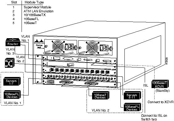
Figure B-11 : Dual Catalyst 5000 Series Switch Configuration---Switch Two
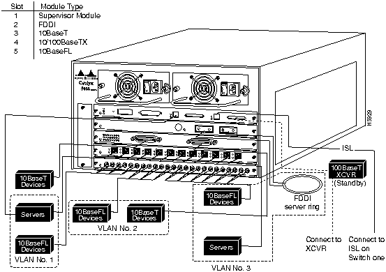
Figure B-12 : Port Configuration Worksheet Slot Number 1---Dual Switch One
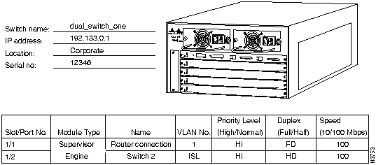
Figure B-13 : Port Configuration Worksheet Slot Number 2---Dual Switch One
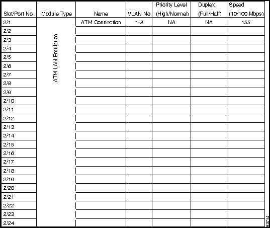
Figure B-14 : Port Configuration Worksheet Slot Number 3---Dual Switch One
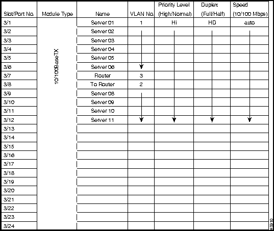
Figure B-15 : Port Configuration Worksheet Slot Number 4---Dual Switch One
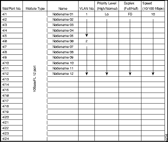
Figure B-16 : Port Configuration Worksheet Slot Number 5---Dual Switch One
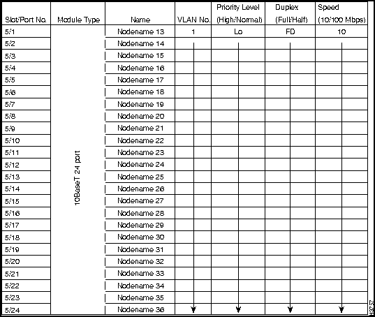
Figure B-17 : Port Configuration Worksheet Slot Number 1---Dual Switch Two Example
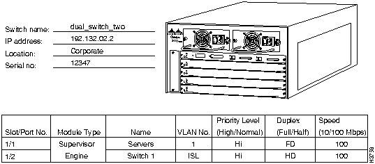
Figure B-18 : Port Configuration Worksheet Slot Number 2---Dual Switch Two
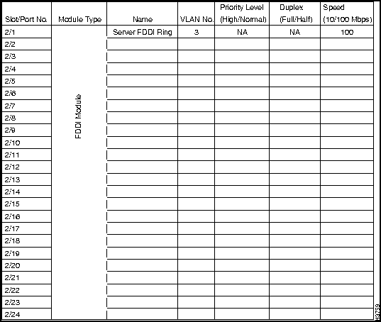
Figure B-19 : Port Configuration Worksheet Slot Number 3---Dual Switch Two
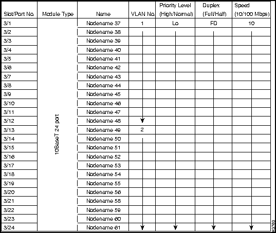
Figure B-20 : Port Configuration Worksheet Slot Number 4---Dual Switch Two
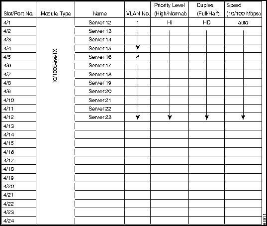
Figure B-21 : Port Configuration Worksheet Slot Number 5---Dual Switch Two
Port Configuration Worksheet Masters
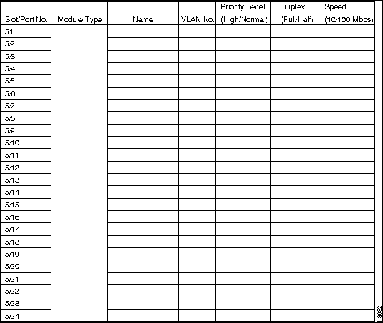
Figure B-22, Figure B-23, Figure B-24, Figure B-25, and Figure B-26 are the blank Port Configuration Worksheets you can fill out before starting to configure the Catalyst 5000 series switch.
Figure B-22 : Port Configuration Worksheet Supervisor Engine Module
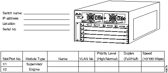
Figure B-23 : Port Configuration Worksheet Slot Number 2
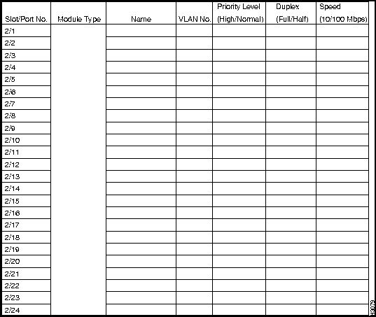
Figure B-24 : Port Configuration Worksheet Slot Number 3
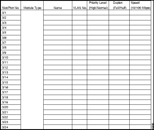
Figure B-25 : Port Configuration Worksheet Slot Number 4
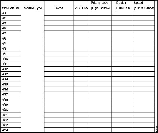
Figure B-26 : Port Configuration Worksheet Slot Number 5
The Site Log (see Figure B-27) is used during subsequent maintenance of the switch. A detailed description of actions performed and symptoms observed should be completed by the person performing the maintenance and kept as part of the permanent site record.
|
|
Copyright 1988-1996 © Cisco Systems Inc.