|
|
This chapter describes the equipment and site requirements for installing the Catalyst 5000 series switch. It includes the power and cabling requirements that must be in place at the installation site and describes additional equipment you will need to complete the installation and the environmental conditions your site must meet to maintain normal operation. Instructions for unpacking the system and additional equipment are provided in the document Unpacking Instructions, which is attached to the outside of the shipping container.
This chapter includes information about the following preinstallation requirements:
The following guidelines will help to ensure your safety and protect the equipment. This list is not inclusive of all potentially hazardous situations that you may be exposed to as you install the switch, so be alert.
![]()
The switch chassis weighs 43 pounds when empty (no switching modules or power supplies installed) and 88 pounds with two power supplies and five interface modules installed. The chassis is not intended to be moved frequently. Before you install the switch, ensure that your site is properly prepared so you can avoid having to move the chassis later to accommodate power sources and network connections.
Two people are required to lift the chassis. Whenever you lift the chassis or any heavy object, follow these guidelines:
Warning Two people are required to lift the chassis. Grasp the chassis underneath the lower edge and lift with both hands. To prevent injury, keep your back straight and lift with your legs, not your back. To prevent damage to the chassis and components, never attempt to lift the chassis with the handles on the power supplies or on the interface processors, or by the plastic panels on the front of the chassis. These handles were not designed to support the weight of the chassis.To see translated versions of this warning, refer to the appendix "Translated Safety Warnings."
![]()
Figure 2-1 : Unsafe Lifting Practices

Working Safely with Electricity
The supervisor engine module, switching modules, and redundant (second) power supplies are designed to be removed and replaced while the system is operating without presenting an electrical hazard or damage to the system. Before removing a redundant power supply, ensure that the first supply is powered on.
You must shut down the system before removing or replacing the supervisor engine module or any of the replaceable components inside the front panel---for example, the backplane. Never install equipment that appears to be damaged.
Follow these basic guidelines when working with any electrical equipment:
In addition, use the guidelines that follow when working with any equipment that is disconnected from a power source but still connected to telephone wiring or other network cabling.
Preventing Electrostatic Discharge Damage
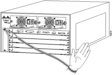
Electrostatic discharge damage (ESD), which occurs when electronic cards or components are improperly handled, can result in complete or intermittent failures. The supervisor engine module and switching modules each consist of a printed circuit card that is fixed in a metal carrier. Electromagnetic interference (EMI) shielding, connectors, and a handle are integral components of the carrier. Although the metal carrier helps to protect the cards from ESD, use a preventive antistatic strap whenever you handle the supervisor engine module or switching modules. Handle the carriers by the handles and the carrier edges only; never touch the cards or connector pins.
Following are guidelines for preventing ESD damage:
Figure 2-2 : Placement of ESD Wrist Strap
This section discusses the site environment requirements for the switch chassis.
The environmental monitor in the switch protects the system and components from potential damage from overvoltage and overtemperature conditions. To ensure normal operation and avoid unnecessary maintenance, plan your site configuration and prepare your site before installation. After installation, make sure the site maintains an ambient temperature of 32 to 104°F (0 to 40°C) and keep the area around the chassis as free from dust as is practical.
The Catalyst 5000 series switch should be installed in an enclosed, secure area such as a wiring closet. The wiring closet provides security, ensuring that only qualified personnel have access to the switch and control of the environment.
The 376W, AC-input power supply uses a power factor corrector (PFC) that allows it to operate on input voltage and current within the ranges of 100 to 240 VAC and 47 to 63 Hz.
A second, identical power supply is also present in chassis configured with the redundant power option. Redundant power ensures that power to the chassis continues uninterrupted in the event that one power supply fails. It also provides uninterrupted power in the event one power line fails; the redundant power supply operates only if the power supplies are connected to separate input lines. Table A-1 in the appendix "System Specifications" lists system power specifications including input voltage and operating frequency ranges.
Note the power consumption rating in Table A-1 in the appendix "System Specifications" for each unit before it is connected.
Following are guidelines for setting up the plant wiring and cabling at your site. When planning the location of the new system, consider the distance limitations for signaling, EMI, and connector compatibility.
Considering Electromagnetic Interference
When wires are run for any significant distance in an electromagnetic field, interference can occur between the field and the signals on the wires. This fact has two implications for the construction of plant wiring:
If wires exceed recommended distances, or if wires pass between buildings, give special consideration to the effect of a lightning strike in your vicinity. The electromagnetic pulse (EMP) caused by lightning or other high-energy phenomena can easily couple enough energy into unshielded conductors to destroy electronic devices. If you have had problems of this sort in the past, you may want to consult experts in electrical surge suppression and shielding.
Most data centers cannot resolve the infrequent but potentially catastrophic problems just described without pulse meters and other special equipment. These problems can cost a great deal of time to identify and resolve, so take precautions by providing a properly grounded and shielded environment, paying special attention to issues of electrical surge suppression.
Setting Up Ethernet and Fast Ethernet Cabling The maximum distances for Ethernet network segments and connections depend on the type of transmission cable used; for example, unshielded twisted-pair (10BaseT). The term 10BaseT is an abbreviation for 10 Mbps transmission, Baseband medium, and T for twisted pair.
The IEEE recommends a maximum distance of 328 feet (100 meters) between station (connection) and switch for 10BaseT connections using category 3 UTP. See Table 2-1 for maximum cable distances.
Table 2-1 : Ethernet and Fast Ethernet Maximum Transmission Distances
Setting Up ATM LAN Emulation Cabling
When using Unshielded Twisted Pair Category five cabling (UTP5) for ATM LAN Emulation, the maximum transmission distance is 328 feet (100 meters). The maximum distances for ATM LAN Emulation fiber optic network connections are determined by the transmitter output power, receiver sensitivity, and type of optical source, as shown in Table 2-2.
Table 2-2 : ATM LAN Emulation FIber Optic Maximum Transmission Distances
ATM Multimode Power Budgeting
The following is an example of multimode power budget calculations with sufficient power for transmission, based on the following variables:
Estimate the power budget as follows:
PB = 11.5 dB -- 3 km (1.0 dB/km) -- 4 (0.5 dB) -- 3 (0.5 dB) -- 0.5 dB (HOL) -- 1 dB (CRM)
PB = 11.5 dB -- 3 dB -- 2 dB -- 1.5 dB -- 0.5 dB -- 1 dB
PB = 2.5 dB
The value of 2.5 dB indicates that this link would have sufficient power for transmission.
ATM Multimode Power Budget Example of Dispersion Limit
Following is an example with the same parameters as the previous example, but with a multimode link distance of 4 km:
PB = 11.5 dB -- 4 km (1.0 dB/km) -- 4 (0.5 dB) -- 3 (0.5 dB) -- 0.5 dB (HOL) -- 1 dB (CRM)
PB = 11.5 dB -- 4 dB -- 2 dB -- 1.5 dB -- 0.5 dB -- 1 dB
PB = 1.5 dB
The value of 1.5 dB indicates that this link would have sufficient power for transmission. However, because of the dispersion limit on the link (4 km x 155.52 MHz > 500 MHz/km), this link would not work with multimode fiber. In this case, single-mode fiber would be the better choice.
Using Statistics to Estimate the Power Budget
Statistical models more accurately determine the power budget than the worst-case method. Determining the link loss with statistical methods requires accurate knowledge of variations in the data link components. Statistical power budget analysis is beyond the scope of this document. For further information, refer to User-Network Interface (UNI) Forum specifications, ITU-T standards, and your equipment specifications.
For Further Reference
The following publications contain information on determining attenuation and power budget:
Approximating the ATM LAN Emulation Switching Module Power Margin
The LED used for a multimode transmission light source creates multiple propagation paths of light, each with a different path length and time requirement to cross the optical fiber, causing signal dispersion (smear). Higher-order mode loss (HOL) results from light from the LED entering the fiber and being radiated into the fiber cladding. A worst-case estimate of power margin (PM) for multimode transmissions assumes minimum transmitter power (PT), maximum link loss (LL), and minimum receiver sensitivity (PR). The worst-case analysis provides a margin of error, although not all the parts of an actual system will operate at the worst-case levels.
See Table 2-3 for maximum cable distances used with the ATM LAN emulation modules.
Table 2-3 : ATM Maximum Transmission Distances
The power budget (PB) is the maximum possible amount of power transmitted. The following equations list the calculation of the power budget:
PB = PT -- PR
PB = --18.5 dBm -- 30 dBm
PB = 11.5 dB
The power margin calculation is derived from the power budget and subtracts the link loss, as follows:
PM = PB -- LL
If the power margin is positive, as a rule, the link will work.
Table 2-4 lists the factors that contribute to link loss and the estimate of the link loss value attributable to those factors.
Table 2-4 : Estimating Link Loss
After calculating the power budget minus the data link loss, the result should be greater than zero. Results less than zero may have insufficient power to operate the receiver.
Setting Up CDDI and FDDI Cabling Copper Distributed Data Interface (CDDI) is the implementation of FDDI protocols over STP and UTP cabling. CDDI transceivers transmit over relatively short distances (about 100 feet), providing data rates of 100 Mbps using a dual-ring architecture to provide redundancy.
The CDDI and FDDI standards set the maximum distances between stations to the fiber and cable lengths listed in Table 2-5 and the typical fiber-optic link attenuation and dispersion limits listed in Table 2-6. The maximum circumference of the FDDI network is only half the specified distance because of signal wrapping or loopback during fault correction. The standard allows a maximum of 500 stations. Both single-mode and multimode transceiver types provide 11 dB of optical power.
Table 2-5 : FDDI Maximum Transmission Distances
Table 2-6 : Typical Fiber-Optic Link Attenuation and Dispersion Limits
Setting Up Serial Cabling As with all signaling systems, serial signals can travel a limited distance at any given bit rate; generally, the slower the baud rate, the greater the distance. Table 2-7 shows the standard relationship between baud rate and distance for EIA/TIA-232 signals.
Table 2-7 : IEEE Standard EIA/TIA-232 Transmission Speed Versus Distance
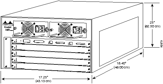
A standard rack-mount kit is provided for mounting the switch in a standard 19-inch equipment rack. The rack-mount kit is not suitable for use with telco-type equipment racks, or those with obstructions (such as a power strip) that could impair access to the switching modules and power supplies. Figure 2-3 show the chassis footprint and outer dimensions.
Figure 2-3 : Chassis Footprint and Outer Dimensions
To use the standard rack-mount kit, your equipment rack must meet the following requirements:
When planning your rack installation, consider the following guidelines:
To see translated versions of this warning, refer to the appendix "Translated Safety Warnings."
In addition to the preceding guidelines, review the precautions for avoiding overtemperature conditions in the section "Ventilating the Equipment-Rack" later in this chapter.
Setting Up the Site Environment
The switch operates as a standalone system mounted in a rack in a secure wiring closet. It requires a dry, clean, well-ventilated, and air-conditioned environment. An internal fan assembly pulls cooling air through the chassis from the rear and right side (intake) to the front and left side (exhaust) when facing the rear of the system. The flow of ambient air must be maintained to ensure normal operation. If the airflow is blocked or restricted, or if the intake air is too warm, an overtemperature condition can occur. Under extreme conditions, the environmental monitor will shut down the system to protect the system components.
To ensure normal operation and avoid unnecessary maintenance, plan your site configuration and prepare your site before installation. After installation, make sure the site maintains an ambient temperature of 0 to 40°C (32 to 104°F) and keep the area around the chassis as free from dust as is practical. For a description of the environmental monitor and status levels, refer to the section "Environmental Monitoring and Reporting" in the chapter "Defining the Catalyst 5000 Series Switch."
Table 2-8 lists the operating and nonoperating environmental site requirements. To maintain normal operation and ensure high system availability, maintain an ambient temperature and clean power at your site. The following ranges are those within which the switch will continue to operate; however, a measurement that is approaching the minimum or maximum of a range indicates a potential problem. You can maintain normal operation by anticipating and correcting environmental anomalies before they exceed the maximum operating range.
Table 2-8 : Specifications for Operating and Nonoperating Environments
Taking Preventive Site Configuration Measures
Planning a proper location for the switch and the layout of your equipment rack or wiring closet is essential for successful system operation. Equipment placed too close together or inadequately ventilated can cause system overtemperature conditions. In addition, chassis panels made inaccessible by poor equipment placement can make system maintenance difficult. Following are precautions that can help avoid problems during installation and ongoing operation.
Follow these general precautions when planning your equipment locations and connections:
Ventilating the Equipment-Rack
If you plan to install the switch in an equipment rack, follow these precautions to avoid overtemperature conditions in addition to the guidelines that are provided in the section "Preparing Equipment Racks" earlier in this chapter:
For a functional description of the environmental monitor and the status levels, refer to the section "Environmental Monitoring and Reporting," in the chapter "Defining the Catalyst 5000 Series Switch."
Take the following precautions when planning power connections to the switch:
When preparing your site for network connections to the switch, you need to consider a number of factors related to each type of interface:
Configuring Network Cabling Components
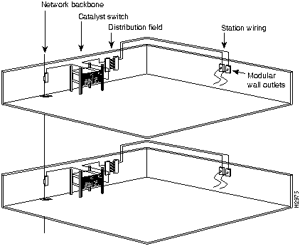
The network cabling components shown in Figure 2-4, consist of the following:
Figure 2-4 : Network Cabling Components
Configuring Additional and Optional Connection Equipment
You may need some of the following data communications equipment to complete your installation.
Setting Up Ethernet Connection Equipment
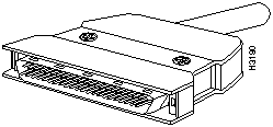
You will need an Ethernet cable between the attached device and the switch port. You can use three different Ethernet connectors:
Figure 2-5 : Fast Ethernet RJ-45 Interface Cable Connectors
Figure 2-6 : Fast-Ethernet 40-Pin MII Interface Cable Connectors
Figure 2-7 : Ethernet Fiber-Optic Connector (ST Type)
Figure 2-8 : Multimode Fiber-Optic Fast Ethernet Connector (SC Type)
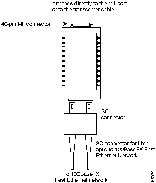
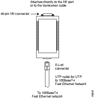
Ethernet transceivers are available from a variety of sources for VTP and multimode fiber-optic cabling (100BaseFX at 100 Mbps). Figure 2-9 and Figure 2-10 show examples of Fast Ethernet transceivers and connection equipment.
Figure 2-9 : Fast Ethernet Fiber Transceivers and Connection Equipment
When planning your connections, consider the types and locations of connectors on adjacent switching modules to avoid having the transceiver overlap and impair access to other connections.
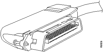
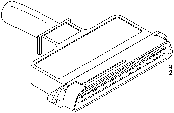
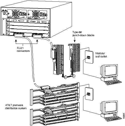
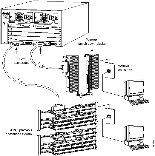
Figure 2-10 : Fast Ethernet UTP Transceivers and Connecting Equipment The two Telco connectors of the 24-port switched 10BaseT module can use both 90o as well as 180o male Telco connectors as illustrated in Figure 2-11 and Figure 2-12. Additional fastenings for the 90o connectors are available by securing Velcro straps around the
Figure 2-11 : Ethernet RJ-25 Telco Interface 90o Cable Connectors
Figure 2-12 : Ethernet RJ-25 Telco Interface 180o Cable Connectors
Figure 2-13 shows a typical Ethernet RJ-21 Telco interface 90o connector, and Figure 2-14 shows a typical Ethernet RJ-21 Telco interface 180o connector, each connected to punch-down blocks and individual workstations using RJ-45 modular connections at the wall outlet in the office. Each RJ-21 Telco connection supports 12 attached devices.
Figure 2-13 : Ethernet RJ-21 Telco Interface 90o Cables with Punch-Down Blocks
Figure 2-14 : Ethernet RJ-21 Telco Interface 180o Cables with Punch-Down Blocks
Setting Up ATM Connection Equipment
All ATM interfaces are full duplex. You must use the appropriate ATM interface cable to connect the ATM multimode or UTP switching module with an external ATM network.
The ATM LAN emulation switching modules provide an interface to ATM switching fabrics for transmitting and receiving data at rates of up to 155 Mbps bidirectionally; the actual rate is determined by the physical layer interface module (PLIM). The ATM LAN emulation switching module can support PLIMs that connect to the following physical layers:
For wide-area networking, ATM is currently being standardized for use in Broadband Integrated Services Digital Networks (BISDNs) by the ITU-T and the American National Standards Institute (ANSI). BISDN supports rates from E3 (34 Mbps) to multiple gigabits per second (Gbps).
The ATM UNI specification defines the required Management Information Base (MIB) functionality for ATM interfaces. Refer to the ATM UNI specification for additional details. ATM UNI information is arranged in a MIB fashion. MIB attributes are readable and writable across the Interim Local Management Interface (ILMI) using Simple Network Management Protocol (SNMP). The ILMI uses SNMP together with the ATM ILMI MIB without User Datagram Protocol (UDP) or Internet Protocol (IP) addressing to provide diagnostics, monitoring, and configuration services at the UNI.
The ATM LAN emulation switching module supports RFC 1213 interface MIBs as specified in the ATM MIB V2 specification.
The ATM interface cable is used to connect the switch to an ATM network or to connect two switches back to back. Cables can be obtained from the following cable vendors:
For 4B/5B traffic over single-mode or multimode fiber, use the single-mode (SC type) connector (see Figure 2-15) to connect the ATM multimode switching module with the external ATM switch.
Figure 2-15 : Single-Mode Network Interface Connector (SC Type)
Setting Up CDDI/FDDI Connection Equipment
Fiber-optic transceivers on the FDDI modules provide a direct interface between the switch and the CDDI/FDDI ring. The FDDI modules support multimode transceivers. Multimode transceivers provide a Class A dual attachment interface that can be connected to a Class A or a Class B station. Class A is a dual attachment station (DAS) with primary and secondary rings; Class B is a single attachment station (SAS) with only a primary ring. See the section "Defining the CDDI/FDDI Station" later in this chapter for a detailed description of Class A and Class B stations and of DASs and SASs.
FDDI networks use two types of fiber-optic cable: single-mode (also called monomode) and multimode. Mode refers to the angle at which light rays (signals) are reflected and propagated through the optical-fiber core, which acts as a waveguide for the light signals. Multimode fiber has a relatively thick core (62.5/125-micron) that reflects light rays at many angles. Single-mode fiber has a narrow core (8.7 to 10/125-micron) that allows the light to enter only at a single angle.
Although multimode fiber allows more light signals to enter at a greater variety of angles (modes), the different angles create multiple propagation paths that cause the signals to spread out in time and limit the rate at which data can be accurately received. This distortion does not occur on the single path of the single-mode signal; therefore, single-mode fiber is capable of higher bandwidth and greater cable run distances than multimode fiber. Multimode transmitters usually use LEDs as a light source. Single-mode transmitters use a laser diode, which is capable of sustaining faster data rates. Multimode transmitters use a photodiode detector at the receiver to translate the light signal into electrical signals.
Configuring CDDI Transceivers and Cable Connections
The CDDI transceiver supports distances of up to 330 feet (100.6 m). The CDDI connector is a CDDI-standard physical sublayer (PHY) connector that encodes and decodes the data into a format acceptable for UTP transmission. The CDDI connector accepts RJ-45 connectors with standard UTP cable as shown in Figure 2-16.
Figure 2-16 : CDDI Interface RJ-45 Connector
Confirm that all existing cables conform with CDDI distance requirements, and ensure that you have the proper connectors (modular RJ-45). Following are cable and distance specifications:
When you plan your CDDI installation, remember the following:
Configuring FDDI Transceivers and Cable Connections
The multimode transceiver supports distances of up to 1.2 miles (2 kilometers). The multimode connector is an FDDI-standard physical sublayer (PHY) connector that encodes and decodes the data into a format acceptable for fiber transmission. The multimode connector accepts standard 62.5/125-micron multimode fiber-optic cable using the MIC and, with proper cable terminators, can accept 50/125 micron fiber-optic cable. Multimode uses the integrated MIC connector, shown in Figure 2-17, at the FDDI modules and the network ends.
Figure 2-17 : Multimode FDDI Network Interface Connector (MIC Type)
The single-mode transceivers support distances up to 18.6 miles (30 kilometers). The single-mode connector accepts standard 8.7 or 10/125-micron single-mode fiber-optic cable using ST-type connectors for transmit and receive ports. (See Figure 2-18.)
Figure 2-18 : FDDI Network Interface Connector (ST Type)
The FDDI modules provide a control port for an optical bypass switch. The control port allows the light signal to pass directly through the bypass switch and completely bypass the FDDI module transceivers when the interface has failed or is shut down. Most optical bypass switches provide the necessary interface cables for connection to the MIC connectors on the FDDI module. However, not all manufacturers use the same type of DIN connector for the control port; some manufacturers use a DIN, and some use a smaller version, a mini-DIN.
Defining the CDDI/FDDI Station
CDDI/FDDI, which specifies a 100-Mbps, token-passing dual-ring network using fiber-optic transmission media, is defined by the ANSI X3.1 standard and by ISO 9314, the international version of the ANSI standard. An FDDI network consists of two token-passing fiber-optic rings: a primary ring and a secondary ring. A CDDI/FDDI ring consists of two or more point-to-point connections between adjacent stations.
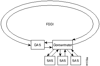
On most FDDI networks, the primary ring is used for data communication, and the secondary ring is used as a backup. Class B, or SASs, attach to one ring and are typically attached through a concentrator which provides connections for multiple SASs; Class A, or DASs, are attached to both rings. Figure 2-19 shows a typical FDDI configuration with both DASs and SASs.
Figure 2-19 : Typical FDDI Configuration with DAS, Concentrator, and SAS
SASs (Class B) typically attach to the primary ring through a concentrator, which provides connections for multiple SASs. The concentrator ensures that a failure or power down of any SAS does not interrupt the ring. SASs use one transmit port and one receive port to attach to the single ring. DASs (Class A) have two physical ports, designated PHY A and PHY B, each of which connects the station to both the primary and secondary rings. Each port is a receiver for one ring and a transmitter for the other. For example, PHY A receives traffic from the primary ring, and PHY B transmits to the primary ring.
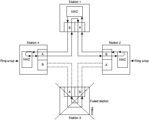
The dual rings in a CDDI/FDDI network provide fault tolerance. If a station on a dual ring shuts down or fails, such as Station 3 in Figure 2-20, the ring automatically wraps (doubles back on itself) to form a single contiguous ring. This removes the failed station from the ring, but allows the other stations to continue operation. In Figure 2-20, the ring wraps to eliminate Station 3 and forms a smaller ring that includes only Stations 1, 2, and 4.
Figure 2-20 : DAS Station Failure and Ring Recovery Example
A second failure could cause the ring to wrap in both directions from the point of failure, which would segment the ring into two separate rings that could not communicate with each other. For example, if Station 1 in Figure 2-20 fails after Station 3 fails, Stations 2 and 4 will each be isolated because no path for communication exists between them. Subsequent failures cause additional segmentation.
Using the Optical Bypass Switch
Optical bypass switches avoid segmentation by eliminating failed stations from the ring. During normal operation, an optical bypass switch allows the light signal to pass uninterrupted directly through itself. When a station with a bypass switch fails, the bypass switch reroutes the signal back onto the ring before it reaches the failed station, so the ring does not have to wrap back on itself.
Figure 2-21 shows an optical bypass switch installed at Station 1. In the normal configuration shown, Station 1 is functioning normally, so the optical bypass switch appears transparent. The switch essentially allows the signals to pass through it without interruption. However, if Station 1 fails, the optical bypass switch enables the bypassed configuration shown on the right in Figure 2-21.
Figure 2-21 : Optical Bypass Operation on a DAS
The bypass switch reroutes the light signal by intercepting it before it reaches the failed Station 1 and sends it back out to the ring. This allows the signal to maintain its existing path and direction without wrapping back on itself. However, stations that are operating normally repeat the signal when sending it back out to the ring. Optical bypass switches
Another technique for fault tolerance is dual homing, whereby critical devices are attached to two concentrators. Only the designated primary concentrator is active unless it (or its link) fails. If the primary switch does fail, the backup (passive) link is activated automatically and sustains the ring.
Configuring EIA/TIA-232 Connections
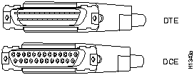
EIA/TIA-232, the most common interface standard in the U.S., supports unbalanced circuits at signal speeds up to 64 kbps. The supervisor engine module console connection is a standard 25-pin D-shell connector (known as a DB-25) that is commonly used for EIA/TIA-232 connections. Figure 2-22 shows the connectors at the local end of the adapter cable. The system console port on the supervisor engine module EIA/TIA-232 connection supports only asynchronous connection. For further information on the console port, refer to the section "Using Console Port Connection Equipment."
When connecting serial devices, consider the adapter cables as an extension of the switch for external connections; therefore, use DTE cables to connect the switch to remote DCE devices such as modems or data service units (DSUs), and use DCE cables to connect the switch to remote DTE devices such as a host or PC. (See Figure 2-22.)
Figure 2-22 : EIA/TIA-232 Adapter Cable Connectors, Network End
Using Console Port Connection Equipment
The supervisor engine module contains an EIA/TIA-232 asynchronous console port (DB-25 receptacle). Synchronous transmission uses precise timing to synchronize transmissions between the transmitter and receiver, and maintains separate clock and data signals. Asynchronous transmission uses control bits instead of a precise clock signal to indicate the beginning and end of characters.
When connecting a serial device, consider the cable as an extension of the switch for an external connection; therefore, use null-modem cable to connect the switch to a remote DCE device such as a modem or data service unit (DSU), and use a straight-through cable to connect the switch to a DTE device such as a terminal or PC.
You will need a terminal to configure the interfaces and bring up the system. You will also need an EIA/TIA-232 DCE console cable to connect the terminal to the console port on the supervisor engine module. After you establish normal operation, you can disconnect the terminal. Both ends of the console cable should be EIA/TIA-232 plugs to enable you to connect to the supervisor engine module DCE console port DB-25 receptacle and to the DB-25 receptacles used on the DTE ports on most terminals.
Before you connect a terminal to the console port, configure the terminal to match the switch console port, as follows:
Verifying the Installation Checklist
Refer to the section "Switch Installation Checklists" (see Figure B-1) in the appendix "Configuration Worksheets" to assist you with your installation and to provide a historical record of what was done, by whom, and when. Make a copy of this checklist and indicate when each procedure or verification is completed. When the checklist is completed, place it in your Site Log (see Figure B-27) along with the other records for your new switch.
Unpacking and Repacking the System
Unpacking instructions are provided in the document Unpacking Instructions, which is attached to the outside of the shipping container; you should have already read that document and followed the procedures to unpack your Catalyst 5000 series switch. Proceed to the next section "Checking the Contents" to verify that you have received everything.
Refer to the section "Switch Installation Checklists" in the appendix "Configuration Worksheets" to check the contents of the shipping container. Use the Switch Installation Checklists to create a record of your order and to ensure that you received all the components you ordered.
Take the following steps to check the contents of your Catalyst 5000 series switch package:
Refer to the sections "Switch Installation Checklists" and "Switch Checklists" that lists all standard components that are included with the switch, along with optional equipment available, in the appendix "Configuration Worksheets." Check each item on the Component List as you unpack and verify it. Insert the completed checklist into the Site Log (described in the section "Switch Installation Checklists" in the appendix "Configuration Worksheets").
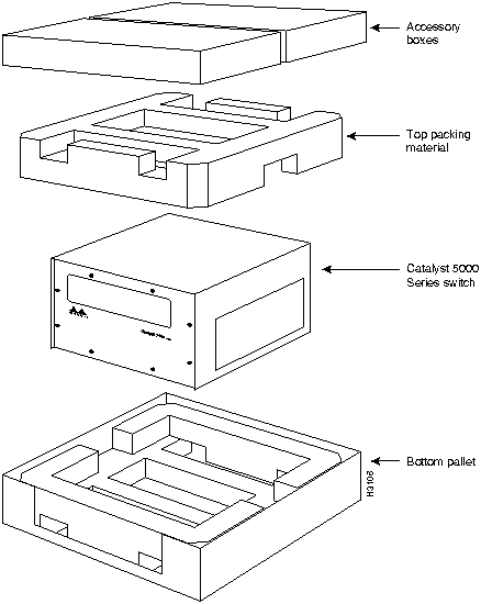
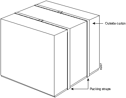
In the event you need to return or move the Catalyst 5000 series switch, the following instructions describe repacking the switch using the original packaging material:
Figure 2-23 : Catalyst 5000 Packing Material
Figure 2-24 : Catalyst 5000 Series Switch Final Package
Copyright 1988-1996 © Cisco Systems Inc.
![]()
![]()
![]()
![]()
![]()
![]()
![]()
Transceiver Speed
Cable Type
Duplex Mode
Maximum Distance between Stations
10 Mbps
Category 3 UTP
Full and half
328 feet (100 meters)
10 Mbps
Multimode fiber
Full and half
1.2 miles (2 km)
100 Mbps
Category 5 UTP
Full and half
328 feet (100 meters)
100 Mbps
Multimode fiber
Full
1.2 miles (2 km)
100 Mbps
Multimode fiber
Half
1,312 feet (400 meters)
100 Mbps
Single-mode fiber
Full and Half
6.2 miles (10 km)
MultiMode Fiber
Single Mode Fiber
Transmitter Output Power:
--19 to --14 dBm
--14 to --8 dBm
Receiver Sensitivity:
--32.5 to --14 dBm
-32.5 to --8 dBm
Wavelength:
1270 to 1380 nm
1261 to 1360 nm
Optical Source:
LED
Laser
Maximum Span:
2 km
10 km
Transceiver Type
Maximum Distance between Stations
Single-mode
6.22 miles (10 km)
Multimode
1.2 miles (2 km)
Category 5 UTP
328 feet (100 meters)
Link Loss Factor
Estimate of Link Loss Value
Higher-order mode losses
0.5 dB
Clock recovery module
1 dB
Modal and chromatic dispersion
Dependent on fiber and wavelength used
Connector
0.5 dB
Splice
0.5 dB
Fiber attenuation
1 dB/km
Transceiver Type
Maximum Distance between Stations
Single-mode
18.6 miles (30 km)
Multimode
1.2 miles (2 km)
UTP
328 feet (100 meters)
Single-Mode
Multimode
Attenuation
0.5 dB
1.0 dB/km
Dispersion limit
No limit
500 MHz/km1
1 The product of bandwidth and distance must be less than 500MHz/km.
Rate (bps)
Distance (Feet)
Distance (Meters)
2400
200
60
4800
100
30
9600
50
15
19200
25
7.6
38400
12
3.7
56000
8.6
2.6
![]()
![]()
or air-conditioned.
![]()
right side clear of obstructions, including dust, and away from the exhaust ports of
other equipment.
Minimum
Maximum
Temperature, ambient operating
32°F (0°C)
104°F (40°C)
Temperature, ambient nonoperating and storage
--4°F (--20°C)
149°F (65°C)
Humidity (RH), ambient (noncondensing) operating
10%
90%
Humidity (RH), ambient (noncondensing) nonoperating and storage
5%
95%
Altitude, operating and nonoperating
Sea level
10,000' (3050 m)
Vibration, operating
5--200 Hz, 0.5 g (1 oct./min.)
Vibration, nonoperating
5--200 Hz, 1 g (1 oct./min.)
200--500 Hz, 2 g (1 oct./min.)

![]()

90o Telco connectors as illustrated in Figure 4-3 and Figure 4-4. The Group Switching
Ethernet module (10BaseT 48-port) requires 180o male Telco connectors for convenient
wiring access.


![]()
![]()
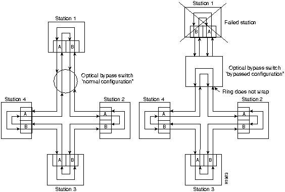
do not repeat or drive the signal (they just allow the signal to pass through them), so significant signal loss can occur when the downstream neighbor (the next station on the ring) is far away.
for each populated interface address. You may need to refer to this worksheet
during installation.
![]()
![]()
![]()
![]()
![]()
![]()
![]()
![]()