|
|
Defining the Catalyst 5000 Series Switch
The Catalyst 5000 series switch provides high-density switched Ethernet and Fast Ethernet for both wiring closet and data-center applications. The switch includes a single, integrated 1.2 gigabit-per-second (Gbps) switching backplane that supports switched 10-megabit-per- second (Mbps) Ethernet with repeater connections and 100-Mbps Fast Ethernet with backbone connections to Fast Ethernet, Asynchronous Transfer Mode (ATM), Fiber Distributed Data Interface (FDDI), and Copper Distributed Data Interface (CDDI). The Catalyst 5000 series switch provides switched connections to individual workstations, servers, LAN segments, backbones, or other Catalyst 5000 switches using shielded twisted-pair (STP), unshielded twisted-pair (UTP), and fiber-optic cable.
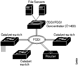
The Catalyst 5000 accommodates up to 96 switched Ethernet interfaces or 192 shared Ethernet interfaces in a standard 19-inch rack. The switch chassis has five slots. The first slot is for the supervisor engine module, which provides Layer 2 switching, local and remote management, and dual Fast Ethernet interfaces. The remaining four slots are for any combination of Ethernet, Fast Ethernet, FDDI/CDDI, and ATM modules. Figure 1-1, Figure 1-2, and Figure 1-3 show examples of configurations that use the Catalyst 5000 series switch.
The use of Layer 2 switching on the Catalyst 5000 prevents unicast packets that are sent between two switched ports from going to all of the other switched ports. Preventing extraneous traffic across switched interfaces increases the bandwidth of all networks.
Typically, the Catalyst 5000 Ethernet interfaces connect workstations and repeaters while the Fast Ethernet interfaces connect to workstations, servers, switches, and routers. The 10/100 BaseTX Fast Ethernet Switching Module supports autosensing and auto-negotia- tion, a process that allows the Catalyst 5000 to negotiate the proper port connection speed (10 or 100 Mbps) and duplex mode (half or full duplex) with an attached device. Fast Ethernet connections can interconnect multiple Catalyst 5000 switches on multiple floors in the different buildings of a campus. Fast Ethernet connections can also act as redundant backup links between switches or expand existing Ethernet networks that need additional capacity.
Figure 1-1 : Cascaded Switches Using Fast Ethernet Interfaces
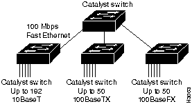
Figure 1-2 : Fast Ethernet As a Backup for ATM Links
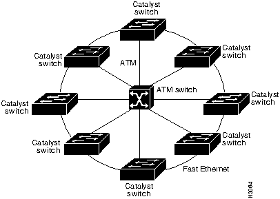
Figure 1-3 : Switches Using an FDDI Backbone
Summarizing Catalyst 5000 Features
The Catalyst 5000 series switch provides the following features:
The Catalyst 5000 architecture is based on high-speed switching network principles, using a queuing model for input and output. Each Catalyst 5000 port maintains its own frame buffer memory. Each frame is stored in a frame buffer before it is forwarded to the next port.
The switch uses central bus arbitration and address recognition logic for all modules. Frame copies are not required for high-speed broadcast and multicast frame forwarding. The switching bus resides on the backplane, operating at 1.2 Gbps, using a 48-bit-wide bus with a 25-MHz clock. Each module port has direct access to the bus through the 192-pin Future Bus connector of each backplane slot. The bus supports a three-level priority request scheme through the bus arbiter. It allows each port to perform a local flush and maintains a packet retry mechanism for outbound port congestion. Refer to the sections "System Architecture" and "Packet Data Flow" for additional information.
The Catalyst 5000 1.2 Gbps media independent backplane provides wire-speed connections for all ports. It supports the following interface and network types:
Encoded Address Recognition Logic (EARL)
Encoded address recognition logic (EARL) is a custom Catalyst 5000 component similar to the learning bridge or content-addressable memory (CAM) of other types of network switches and routers. The Catalyst 5000 EARL automatically learns source MAC addresses and saves them in a RAM address table with virtual LAN (VLAN) and port information. The EARL uses learned entries as destination addresses (DAs) and directs packets using port information contained in the DAs.
Bus arbitration and EARL are shared among all ports. Together they control the destination of packet transfers and access to the data switching bus.
The Catalyst 5000 supports wire-speed, single-stream 10 Mbps Ethernet and 100Mbps Fast Ethernet packet transmission for packet sizes from 64-bytes to 1500-bytes. The switch supports wire-speed, multiple-stream 10 Mbps Ethernet traffic throughput with no packet loss when 50 pairs of interfaces are configured.
The Catalyst 5000 supports three levels of priority on the data switching bus to handle an over-subscribed interface. Two of these priority levels are user-defined; each interface can be set as either High priority or Normal priority (the default is Normal). To serve time-sensitive traffic such as voice or video, bus arbitration logic is maintained in separate logical queues for each priority class; this guarantees that high-priority queues are served first.
The Catalyst 5000 series switch is designed with the following features for maximum network uptime:
When creating fault-tolerant internetworks, a loop-free path must exist between all nodes in a network. A spanning-tree algorithm is used to calculate the best loop-free path throughout a Catalyst 5000 series switched network. Spanning-tree packets are sent and received by switches in the network at regular intervals. The packets are not forwarded by the switches participating in the spanning tree, but are instead processed to determine the spanning tree itself. The IEEE 802.1D bridge protocol, called Spanning Tree Protocol (STP), performs this function for Catalyst 5000 switches.
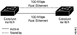
The Catalyst 5000 series switch uses STP on all Ethernet and Fast Ethernet-based virtual local area networks (VLANs). The STP detects and breaks loops by placing some connections in a standby mode, which are activated in the event of a failure. A separate
STP runs within each configured VLAN, ensuring legal Ethernet topologies throughout
the network.
The supported STP states are as follows:
The state for each VLAN is initially set by the configuration and later modified by the STP process. After the port-to-VLAN state is set, the 802.1D bridge specification determines whether the port forwards or blocks packets. Ports can be configured to immediately enter STP forwarding mode when a connection is made, instead of the usual sequence of blocking. learning, and then forwarding. This is useful in situations where immediate access to a server is required.
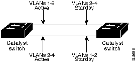
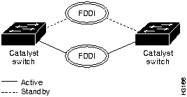
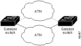
You can design fault-tolerant connections using Ethernet only or Ethernet combined with other topologies. Refer to Figure 1-4 through Figure 1-7 for STP examples.
Figure 1-4 : Fault-Tolerant Fast Ethernet Topology Example
You can design fault-tolerant connections with increased capacity using STP costing. Refer to Figure 1-5, in which the bandwidth is doubled between switches.
Figure 1-5 : Fault-Tolerant Fast Ethernet Topology with Increased Capacity Example
Figure 1-6 : Fault-Tolerant FDDI Topology Example
Figure 1-7 : Fault-Tolerant ATM Topology Example
Virtual Local Area Network (VLAN)
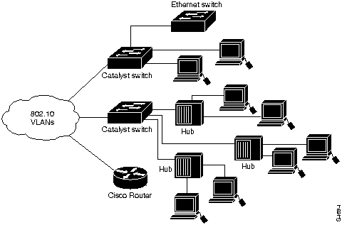
A VLAN on a Catalyst 5000 is essentially a broadcast domain. Only end stations within the VLAN receive packets that are unicast, broadcast, and multicast (flooded) from within the VLAN. A VLAN enhances performance by limiting traffic; it allows the transmission of traffic among stations that belong to it and blocks traffic from other stations and VLANs. VLANs can provide security barriers (firewalls) between end stations that are connected through the same switch.
A VLAN can also be described as a group of end stations, independent of physical location, with a common set of requirements. For example, several end stations may be grouped as a department, such as engineering or accounting. If the end stations are located in close proximity to one another, they can be grouped into a LAN segment. If any of the end stations are on a different LAN segment, typically located in different buildings or locations, they can be grouped together into a VLAN that has all the same attributes as a LAN even though the end stations are not all on the same LAN segment. The information identifying a packet as part of a specific VLAN is preserved across a Catalyst 5000 connection to a router or other switch.
The VLANs on a Catalyst 5000 greatly simplify adding and moving end stations on a network. For example, when an end station is physically moved to a new location, its attributes can be reassigned from a network management station (that is, a console terminal attached to a Catalyst 5000 or through a modem that connects to the console port on the supervisor engine module) using SNMP or the command line interface. When an end station is moved within the same VLAN, it retains its previously assigned attributes in its new location. When an end station is moved to a different VLAN, the attributes of the new VLAN are applied to the end station, depending upon the security levels in place.
The IP address of a Catalyst 5000 series switch Network Management Processor (NMP) can be assigned to any VLAN. This mobility of the IP address allows a network management station and workstations on any VLAN on a Catalyst 5000 series switch to directly access another Catalyst 5000 series switch on the same VLAN without the use of a router. Only one IP address can be assigned to a Catalyst 5000 series switch; therefore, if the IP address is reassigned to a different VLAN, the previous IP address assignment to a VLAN is no longer valid.
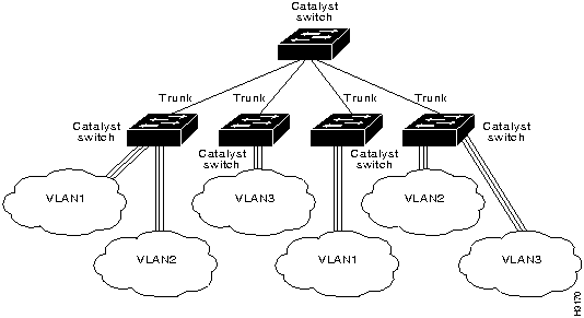
A trunk is a physical link between two Catalyst 5000 series switches or between Catalyst 5000 series switches and routers that carries the traffic of multiple VLANs. Trunks allow you to extend VLANs from one Catalyst 5000 switch to another. Users usually connect switches to each other and to routers using high-speed interfaces, such as Fast Ethernet, FDDI, and ATM.
The Catalyst 5000 series switch provides a means of multiplexing up to 1000 VLANs between switches and routers by using the following methods or protocols:
You can use any combination of these trunk technologies to form enterprise-wide VLANs. You can choose between low-cost copper and long-distance fiber connections for your trunks.
Inter-switch Links (ISLs) on Fast Ethernet Ports
Any Fast Ethernet port can be configured as a trunk. Trunks use Inter-switch link (ISL) protocol to support multiple VLANs. An ISL trunk is like a continuation of the switching backplane. It provides a means for the Catalyst 5000 to multiplex up to 1000 VLANs between switches and routers.
The Dynamic ISL (DISL) Protocol dynamically configures trunk ports between Catalyst 5000 series switches; it synchronizes the configuration of two interconnected Fast Ethernet interfaces into becoming ISL trunks. DISL Protocol minimizes VLAN trunk configuration procedures because only one end of a link must be configured as a trunk or non-trunk.
Figure 1-8 shows an example of a Fast Ethernet ISL configuration.
Figure 1-8 : Fast Ethernet ISL Configuration Example
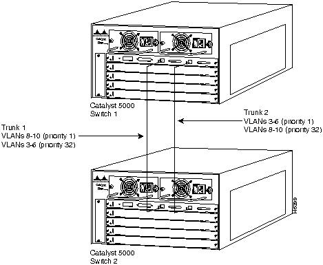
Load Sharing on Trunks Load sharing allows VLAN traffic on parallel Fast Ethernet ISL trunks to be split between multiple trunks. By setting STP parameters on a VLAN basis, you can define which VLANs have priority access to a trunk and which are to use the trunk as a backup when another trunk fails.
In STP, low integer values have the highest priority. Therefore, when you assign spanning-tree port priorities that are lower than the default value of 32 to VLANs, the traffic of those VLANs travels on the trunk with the lowest integer value. The spanning-tree port priority must be set to the same value at both ends of each trunk on each Catalyst 5000 series switch.
For example, Figure 1-9 illustrates two trunks that are connected to the ports of supervisor engine modules on two Catalyst 5000 series switches. The port cost of carrying VLAN traffic across these trunks is equal.
This splits VLAN traffic between the two trunks and increases the throughput capacity and fault tolerance between Catalyst 5000 switches; trunk 1 carries traffic for VLANs 8 through 10, and trunk 2 carries traffic for VLANs 3 through 6. If either trunk fails, the remaining trunk carries the traffic for all of the VLANs. For detailed commands and examples of load sharing, refer to the Catalyst 5000 Series Configuration and Command Reference.
Figure 1-9 : Spanning-Tree Load Sharing Using VLAN Priority
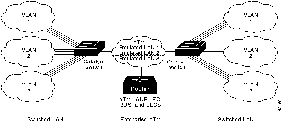
The Catalyst 5000 ATM module provides an interface to switch LANs across an ATM network, supplying LAN users with access to ATM-based services. LAN emulation (LANE) extends virtual LAN (VLANs) throughout the network by establishing point-to-point ATM virtual-circuit connections between switches on the same VLAN.
Using a Catalyst 5000 ATM module, you can set up the following client and servers for LAN emulation:
Figure 1-10 shows an example of an ATM LAN emulation configuration.
Figure 1-10 : ATM LAN Emulation to Extend VLANs Example
FDDI VLANs and 802.10 Protocol
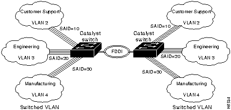
VLANs can be extended across an FDDI network by multiplexing switched packets over a CDDI/FDDI interface using the 802.10 protocol. Using 802.10, Catalyst 5000 CDDI/FDDI interface links can operate as inter-switch trunks that provide broadcast control between configured VLANs. The 802.10 protocol encapsulates a VLAN identifier and packet data according to the IEEE 802.10 specification. CDDI/FDDI interfaces that support 802.10 make selective forwarding decisions within a network domain based upon the VLAN identifier.
The VLAN identifier is a user-configurable 4-byte Security Association ID (SAID). The SAID identifies traffic as belonging to a particular VLAN and determines which VLAN each packet is switched to on the bus.
Refer to Figure 1-11 for an example of configuring FDDI trunks. In this example, the SAID ensures that packets destined for VLAN 1 only reach VLAN 1 after they are transmitted across the FDDI trunks. Refer to Figure 1-12 for an example of an FDDI 802.10 VLAN network configuration.
Figure 1-11 : FDDI Trunks Configuration Example
Figure 1-12 : FDDI 802.10 VLAN Network Configuration Example
VTP provides CDDI/FDDI module configuration for 802.10-based VLANs. VTP requires a protocol type (Ethernet, FDDI, or Token Ring) to be configured for each VLAN. A VLAN can only have one type associated with it. Each VLAN type must have its own unique identifier, and translations between different identifiers must be mapped. VTP advertises VLAN translation mappings to all Catalyst 5000s in a management domain.
Catalyst 5000 FDDI/CDDI modules can integrate switched Ethernet and Fast Ethernet LANs into the FDDI network. To map an 802.10 FDDI VLAN to an Ethernet VLAN, you must map the 802.10 VLAN SAID to an Ethernet VLAN.
If a CDDI/FDDI module receives a a packet containing a VLAN SAID that matches a Catalyst 5000 locally supported Ethernet VLAN, the CDDI/FDDI module translates the packet into Ethernet format and forwards it across the switch backplane to the Ethernet module. CDDI/FDDI modules filter the packets they receive from reaching the backplane if the VLAN SAIDs in the packets do not match a locally supported VLAN.
For example, Figure 1-13 illustrates the configuration for forwarding a packet from the Ethernet module port 1 in slot 2 to the FDDI module port 1 in slot 5. For this example, you would specify the translation of Ethernet VLAN 2 to FDDI VLAN 22. FDDI VLAN 22 is then also automatically translated to Ethernet VLAN 2. The VLAN SAID must be identical on both FDDI modules. Since 802.10 CDDI/FDDI interface links can operate as inter-switch trunks, you can configure multiple VLAN translations over a link.
Figure 1-13 : VLAN Identifiers for an FDDI 802.10 Configuration
CDDI/FDDI modules also support one native (non-trunk) VLAN, which handles all non-802.10 encapsulated FDDI traffic. A translation number need not be configured for the native VLAN since packets that are forwarded to the native VLAN do not contain VLAN identifiers. To map an Ethernet VLAN to an FDDI native VLAN, you must configure the Ethernet VLAN with the VLAN identifier, module number, and port number of the FDDI native VLAN.
Rejecting MAC Address Learning (fddicheck)
An FDDI interface can reject the learning of MAC addresses that it previously learned from an Ethernet interface using the fddicheck user-configurable option. This feature resolves the problem that occurs when VOID frames occur on the FDDI ring and translated Ethernet frames sent by the FDDI interface are received and learned on the same FDDI interface instead of stripped by the MAC hardware.
Disabling Automatic Packet Recognition and Translation (APART)
To increase throughput performance, you can disable the software content-addressable memory (CAM) of the FDDI module. The CAM stores Internet packet exchange (IPX) translation information to support automatic packet recognition and translation (APART). Disabling the FDDI module CAM disables APART. However, the Catalyst 5000 EARL CAM continues to provide packet forwarding functionality.
There are some serious drawbacks to disabling the FDDI software CAM. Disabling APART means that only default IPX translations are used. FDDI module hardware filtering is disabled, and all traffic from the FDDI ring is translated and forwarded to the Catalyst backplane before the EARL CAM can filter it. This could greatly affect system performance. Additionally, the fddicheck user-configurable option is disabled when APART is disabled.
When new VLANs are added to a Catalyst 5000 Series switch in a management domain, VLAN Trunk Protocol (VTP) automatically distributes the information to other devices in the management domain. This allows VLAN naming consistency, and connectivity between all devices in the domain. The VTP is transmitted on all trunk connections, including Inter-switch Link (ISL), 802.10, and ATM LAN emulation (LANE).
The Catalyst 5000 series switch transmits VTP frames on its trunk ports, advertising its management domain name, configuration revision number, and VLAN information that it has learned. Other Catalyst 5000 series switches in the domain use these advertisements to learn about any new VLANs that are configured in the transmitting switch. This process of advertising and learning allows a new VLAN to be created and configured on only one switch in the management domain and be automatically learned about by all other devices in the domain.
You can have redundancy in a network domain by using multiple VTP servers. Only a few VTP servers are required in a large network. All devices are normally VTP servers in a small network. You can enable VTP transparent mode for devices that are not designed to support VTP, or are not configured to participate in VTP.
You can manage your Catalyst 5000 series switch through a console port using either the command line interface (CLI) or other methods for performing network management functions, such as Cisco Discovery Protocol (CDP), Embedded Remote Monitoring (RMON), or Switched Port Analyzer (SPAN). The console port is an EIA/TIA-232 interface to which you can connect a console terminal or modem.
Through the console port, you can directly access the CLI or configure a Serial Line Internet Protocol (SLIP) interface to access network management functions, such as Telnet, ping, Simple Network Protocol (SNMP), and so on. You can assign the IP address for the Catalyst 5000 to any VLAN. You can direct Telnet to access the IP address of the Catalyst 5000 to reach the CLI. You can also use the IP address of the switch to access an SNMP agent.
Supporting Switched Internetwork Management Applications
The Catalyst 5000 supports the following internetwork management applications:
Simple Network Management Protocol (SNMP)
Simple Network Management Protocol (SNMP) is an application-layer protocol designed to facilitate the exchange of management information between network devices. The SNMP system consists of three parts: SNMP manager, SNMP agent, and Management Information Base (MIB).
Instead of defining a large set of commands, SNMP places all operations in a get-request, get-next-request, and set-request format. For example, an SNMP manager can get a value from an SNMP agent or store a value into that SNMP agent. The SNMP manager can be part of a network management system (NMS), and the SNMP agent can reside on a networking device such as a switch. The SNMP agent can respond to MIB-related queries being sent by the NMS.
Following are basic functions supported by SNMP agents:
The Catalyst 5000 series switch provides outgoing Telnet functionality from the command line interface; this feature allows a network manager to use Telnet from the command line interface of the switch to other devices on the network. Moreover, using Telnet, a network manager can maintain a connection to a Catalyst 5000 series switch while also connecting to another switch or router.
Cisco Discovery Protocol (CDP)
Cisco Discovery Protocol (CDP) is media- and protocol-independent and runs on all Cisco-manufactured equipment including routers, bridges, access and communication servers, and switches. With CDP, network management applications can retrieve the device type and SNMP-agent address of neighboring devices. This enables applications to send SNMP queries to neighboring devices.
CDP meets a need created by the existence of lower-level, virtually transparent protocols. CDP allows network management applications to dynamically discover Cisco devices that are neighbors of already known devices, in particular, neighbors running lower-layer, transparent protocols. CDP runs on all media that support Subnetwork Access Protocol (SNAP), including LAN and Frame Relay. CDP runs over the data link layer only, not the network layer. Therefore, two systems that support different network layer protocols can learn about each other.
Cached CDP information is available to network management applications. Cisco devices never forward a CDP packet. When new information is received, old information is discarded.
Embedded Remote Monitoring (RMON)
The Catalyst 5000 series switch provides support for the embedded remote monitoring (RMON) of Ethernet and Fast Ethernet ports. Embedded RMON provides you with visibility into network activity. It enables you to access and remotely monitor the RMON specification RFC 1757 groupings of statistics, historical information, alarms, and events for any port, through SNMP or the TrafficDirector Management application.
The RMON feature monitors network traffic at the link layer of the OSI model without requiring a dedicated monitoring probe or network analyzer. It allows a network manager to analyze network traffic patterns, set up proactive alarms to detect problems before they affect users, identify heavy network users as candidates to move to dedicated or higher speed ports, and perform trend analysis for long-term planning.
The statistics group of the RMON specification maintains utilization and error statistics for the switch that is monitored. Statistics include information about: collisions; cyclic redundancy checks (CRC) and alignment; undersized or oversized packets; jabber; fragments; broadcast, multicast, and unicast messages; and bandwidth utilization.
The history group takes periodic samples from the statistics section and stores them for later retrieval. This includes information such as utilization, error counts, and packet counts.
A system network administrator uses the alarm group to set a sampling interval and threshold for any RMON recorded item. Examples of alarm settings include absolute or relative values, rising or falling thresholds of utilization, packet counts, and CRC errors.
The event group allows events (generated traps) to be logged, printed, and provided to a network manager. The time and date is recorded with each logged event. Network managers use the event group to create customized reports that are based on alarm types.
Extended RMON capabilities are provided through the use of a Cisco SwitchProbe connected to the switch's SPAN port. Refer to the section "Switched Port Analyzer (SPAN)" for additional information.
The Catalyst 5000 series switch switched port analyzer (SPAN) enables you to monitor traffic on any port for analysis by a sniffer or RMON probe. Enhanced SPAN (E-SPAN) enables you to monitor traffic from a VLAN (multiple ports) to a port for analysis. The SPAN redirects traffic from an Ethernet, Fast Ethernet, or FDDI port or VLAN to an Ethernet or Fast Ethernet monitor port for detailed analysis and troubleshooting. You can monitor a single port or VLAN using a dedicated analyzer, such as a Network General Sniffer, or remote monitoring (RMON) probe, such as a Cisco SwitchProbe.
Serial Line Internet Protocol (SLIP)
You can access the Catalyst 5000 series switch command line using Serial Line Internet Protocol (SLIP). This protocol is a version of Internet Protocol (IP) that runs over serial links, allowing IP communications through the console port.
The Catalyst 5000 series switch uses the following standard internet protocols:
The Catalyst 5000 series switch supports standard and enterprise-specific MIBs. The following MIBs are supported:
Refer to "Appendix C, Workgroup MIB Reference," of the Catalyst 5000 Series Configuration Guide and Command Reference (1.4) publication for descriptions of the MIBs offered.
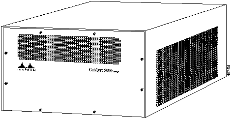
The front panel of the switch (see Figure 1-14) provides access to the switch backplane. You can mount the switch in:
Mounting the Catalyst 5000 series switch with the back facing out provides easy access to all system components, cables, network connections, diagnostic LEDs, and power supply(ies).
A rack-mount kit is included for mounting the chassis in an EIA-310-C standard 19-inch equipment rack. For rack-mounting installation instructions, refer to the section "Rack-Mounting the Switch" in the chapter "Rack-Mounting Instructions."
Figure 1-14 : Front View of the Catalyst 5000 Series Switch
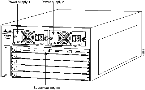
The rear of the switch (see Figure 1-15) provides access to the supervisor engine and modules, power supply(ies), and fan assembly in the switch. The LEDs on the supervisor engine module indicate normal system operation, switch load, and the currently active power supplies. The status LED indicates that the system is in normal operating state. The fan LED indicates fan operating status. The power supplies LEDs (PS1 and PS2) indicate that a power supply is installed in the indicated power supply bay and is providing power to the system.
The power LEDs go out if the power supply in the corresponding bay reaches an out-of-tolerance temperature or voltage condition. (For descriptions of thresholds and status levels, refer to the section "Environmental Monitoring and Reporting" later in
Figure 1-15 : Rear View of the Catalyst 5000 Series Switch
One 376-watt power supply is standard equipment in the switch. A second, identical power supply provides a fault-tolerant power option. Load sharing and redundancy are automatically enabled when a second power supply is installed and powered on; no configuration is required. Each supply has an individual power switch, power cord, and status LEDs on the supervisor engine module. When only one power supply is used, it can be installed in either power supply bay.
The switch consists of the following hardware components:
Hot-swappable modules allow you to add, replace, or remove modules without interrupting the system power, entering any console commands, or causing other software or interfaces to shut down. The redundant power supply option provides dual load-sharing power supplies that maintain input power without interruption if one supply fails. Environmental monitoring and reporting functions enable you to maintain normal system operation by resolving adverse environmental conditions prior to loss of operation. If conditions reach critical thresholds, the system may shut down to avoid damage to equipment from excessive heat or electrical current. Downloadable software and Flashcode allow you to load new images into Flash memory remotely---without having to physically access the switch---for fast, reliable system upgrades.
All modules, fans, and dual, fault-tolerant power supplies support hot swapping. Only the functions performed by the removed component are affected. The supervisor engine module enables switching and controls data across the switch backplane, so it must be present for the system to operate.
The supervisor engine module (see Figure 1-16) is the main system processor in the switch. The supervisor engine module contains the Layer 2 switching engine and network management processor for the system software, and most of the system memory components. It maintains and executes the management functions that control the system. Each supervisor engine stores all interface configurations in nonvolatile memory.
Three supervisor engine module types are available: a module containing Fast Ethernet RJ-45 and media-independent interface (MII) connector interfaces, as shown in Figure 1-16; a module containing Fast Ethernet multimode fiber-optic SC connector interfaces (MMF), as shown in Figure 1-17; and a module containing Fast Ethernet single-mode fiber-optic SC interfaces (SMF), as shown in Figure 1-19. Only one supervisor engine can be installed in the Catalyst 5000 series switch at one time.
Figure 1-16 : Supervisor Engine Module with RJ-45 and Media-Independent Interface (MII) Connectors
Figure 1-17 : Multimode Fiber-Optic Supervisor Engine Module
Figure 1-18 : Single-Mode Fiber-Optic Supervisor Engine Module
The supervisor engine module has the following features:
In addition to these features, the supervisor engine module performs the following management functions:
The supervisor engine module must be installed in the slot labeled 1, which is the top slot when facing the back panel. (See Figure 1-15.)
Flash Memory
The embedded Flash memory allows you to remotely load and store system software images. You can download a new software image over the network or from a local TFTP server and add the new image to Flash memory or replace an existing file.
EEPROM
An electronically erasable programmable read-only memory (EEPROM) component on the supervisor engine module stores module-specific information such as the module serial number, part number, controller type, hardware revision, configuration information, and other details unique to each module. In addition to this standard information, the supervisor engine module EEPROM also contains an address allocator, which is a bank of 1,024 hardware or MAC-level addresses, one for each possible VLAN in the system. For an explanation of the hardware addressing function, refer to the section "Allocating MAC Addresses" later in this chapter.
LEDs
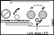
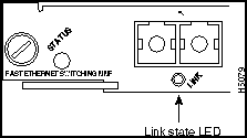
The LEDs on the supervisor engine module indicate the status of the system, which includes the fan assembly and power supply(ies), and the supervisor engine module. The supervisor engine module LEDs are shown in Figure 1-19, Figure 1-20, and Figure 1-21 and described in Table 7-1 in the chapter "Confirming the Installation."
Figure 1-20 : LEDs for Multimode Fiber-Optic Supervisor Engine Module
Figure 1-21 : LEDs for Single-Mode Fiber-Optic Supervisor Engine Module
Access to the reset switch, located behind the faceplate of the supervisor engine module, is through a small hole approximately 1.5 inches to the right of the supervisor engine module status LED. (See Figure 1-19.)
The console port is the local (out-of-band) console terminal connection to the switch---a DB-25 female connector. To use the console port, connect an EIA/TIA-232 terminal (configured for 9600 baud, no parity, eight data bits, and one stop bit), modem, or network management workstation. The console port enables you to perform the following functions:
Fast Ethernet ports 1 and 2 provide two Fast Ethernet interfaces, operating in full- or half-duplex mode. These ports require the following connectivity:
Each Fast Ethernet port has two status LEDs, the 100-Mbps and Link LEDs, which are described in Table 7-1 in the chapter "Confirming the Installation."
Group Switching Ethernet Module (10BaseT 48 Port)
The Ethernet Group Switching Module (10BaseT 48 port), shown in Figure 1-22, provides connection to 48 10-Mbps (10BaseT) Ethernet ports, in four switched segments of 12 ports each. There are four Telco RJ-21 connectors on the front panel (12 interfaces per port). The telco connectors are numbered right to left.
Figure 1-22 : Group Switching Ethernet Module (10BaseT 48 Port)
The LEDs provide status information for the module and individual 10BaseT Ethernet port connections. The LEDs are shown in Figure 1-23 and described in Table 9-2 in the chapter "Confirming the Installation."
Figure 1-23 : Group Switching Ethernet Module (10BaseT 48 Port) LEDs
Ethernet Switching Module (10BaseT 24 Port)
The Ethernet Switching Module (10BaseT 24 port), shown in Figure 1-24, provides connection to 24 switched 10-Mbps (10BaseT) full- or half-duplex Ethernet interfaces using two Telco RJ-21 female ports (12 interfaces per port).
Figure 1-24 : Ethernet Switching Module (10BaseT 24 Port)
The LEDs provide status information for the module and individual 10BaseT Ethernet port connections. The LEDs are shown in Figure 1-25 and described in Table 9-3 in the chapter "Confirming the Installation."
Figure 1-25 : Ethernet Switching Module (10BaseT 24 Port) LEDs
Ethernet Switching Module (10BaseFL 12 Port)
The Ethernet Switching Module (10BaseFL 12 port), shown in Figure 1-26, provides connection to 12 switched 10-Mbps (10BaseFL fiber-optic) full- or half-duplex Ethernet interfaces using 12 multimode (ST) fiber-optic connections.
Figure 1-26 : Ethernet Switching Module (10BaseFL 12 Port)
The LEDs provide status information for the module and individual Fast Ethernet interface connections. The LED is shown in Figure 1-27 and described in Table 9-4 in the chapter "Confirming the Installation."
Figure 1-27 : Ethernet Switching Module (10BaseFL 12 Port) LEDs
10/100 Mbps Fast Ethernet Switching Module (10/100BaseTX 12 Port)
The 10/100 Mbps Fast Ethernet Switching Module (10/100BaseTX 12 port), shown in Figure 1-28, provides connection to 12 switched 10/100-Mbps (10/100BaseTX Category 5 UTP) full- or half-duplex Fast Ethernet interfaces using 12 RJ-45 female connections.
Figure 1-28 : 10/100 Mbps Fast Ethernet Switching Module (10/100BaseTX 12 Port)
The LEDs provide status information for the module and individual 10/100 Mbps Fast Ethernet interface connections. The LEDs are shown in Figure 1-29 and described in the section "10/100 Mbps Fast Ethernet Switching Module (10/100BaseTX 12 Port) LEDs" in Table 9-5 in the chapter "Confirming the Installation."
Figure 1-29 : 10/100 Mbps Fast Ethernet Switching Module (10/100BaseTX 12 Port) LEDs
Fast Ethernet Switching Module (100BaseTX 12 Port)
The Fast Ethernet Switching Module (100BaseTX 12 port), shown in Figure 1-30, provides connection to 12 switched 100-Mbps (100BaseTX Category 5 UTP) full- or half-duplex Fast Ethernet interfaces using 12 RJ-45 female connections.
Figure 1-30 : Fast Ethernet Switching Module (100BaseTX 12 Port)
The LEDs provide status information for the module and individual Fast Ethernet interface connections. The LEDs are shown in Figure 1-31 and described in Table 9-6 in the chapter "Confirming the Installation."
Figure 1-31 : Fast Ethernet Switching Module (100BaseTX 12 Port) LEDs
Fast Ethernet Switching Module (100BaseFX 12 Port)
The Fast Ethernet Switching Module (100BaseFX 12 port), shown in Figure 1-32, provides connection to 12 switched 100-Mbps (100BaseFX fiber-optic) full- or half-duplex Fast Ethernet interfaces using 12 multi-mode (SC) fiber-optic connections.
Figure 1-32 : Fast Ethernet Switching Module (100BaseFX 12 Port)
The LEDs provide status information for the module and individual Fast Ethernet interface connections. The LEDs are shown in Figure 1-33 and described in Table 9-7 in the chapter "Confirming the Installation."
Figure 1-33 : Fast Ethernet Switching Module (100BaseFX 12 Port) LEDs
ATM LAN Emulation Module (UTP)
The ATM LAN emulation module provides a direct connection between the 155-Mbps ATM network and the switch using one RJ-45 connector. (See Figure 1-34.)
Figure 1-34 : ATM LAN Emulation Module (UTP)
The LEDs provide status information for the module and the individual ATM port. The LEDs are shown in Figure 1-35 and described in Table 9-8.
Figure 1-35 : ATM LAN Emulation Module (UTP) LEDs
The PLIM on the ATM module determines the type of ATM connection. There are no restrictions on slot locations or sequence; an ATM fiber optic line module can be installed in any available module slot.
The ATM multimode module supports the following features:
ATM LAN Emulation Module (Single-Mode and Multimode Fiber)
The ATM LAN emulation module provides a direct connection between the 155-Mbps ATM network and the switch using a single SC fiber-optic connector. (See Figure 1-36.)
Figure 1-36 : ATM LAN Emulation Module (Single-Mode and Multimode Fiber)
The LEDs provide status information for the module and individual port connections. The LEDs are shown in Figure 1-37 and described in Table 9-9.
Figure 1-37 : ATM LAN Emulation Module (Single-Mode and Multimode Fiber) LEDs
The physical layer interface module (PLIM) on the ATM module determines the type of ATM connection. There are no restrictions on slot locations or sequence; an ATM module can be installed in any available module slot.
The CDDI Module, shown in Figure 1-38, provides a single or dual attachment station connection to two (Category 5 UTP) 100-Mbps CDDI interfaces using two RJ-45 female connections.
The LEDs provide status information for the module and individual Ethernet port connections. The LEDs are shown in Figure 1-39 and described in Table 9-10.
Figure 1-39 : CDDI Module LEDs
FDDI Module MMF (Multimode Fiber)
The FDDI module MMF (multimode fiber), shown in Figure 1-40, provides a single or dual attachment station connection to the FDDI backbone network using multimode (media interface connector [MIC]) fiber-optic connections.
Figure 1-40 : FDDI Module MMF (Multimode Fiber)
The LEDs provide status information for the module and the individual FDDI port connections. The LEDs are shown in Figure 1-41 and described in Table 9-11.
Figure 1-41 : FDDI Module MMF (Multimode Fiber) LEDs
Multimode Fiber Optical Bypass Switch Connector
The six-pin mini-DIN connector connects an external optical bypass switch to the module. An activated bypass switch inserts the module into the ring. The optical bypass switch LED indicates the status of the device connected to the module. When the LED is on, the bypass switch is activated and is in Thru mode (the module is attached to the dual ring). Use a bypass switch only with the A/B port card option. If you install or remove an optical bypass switch, you must reset the FDDI module.
FDDI Module SMF (Single-Mode Fiber)
The module (single-mode fiber), shown in Figure 1-42, provides a single or dual attachment station connection to the 100-Mbps FDDI backbone network using two single-mode (ST) fiber-optic connections.
Figure 1-42 : FDDI Module SMF (Single-Mode Fiber)
The LEDs provide status information for the module and individual FDDI port connections. The LEDs are shown in Figure 1-43 and described in Table 9-12.
Figure 1-43 : FDDI Module SMF (Single-Mode Fiber) LEDs
Single-Mode Fiber Optical Bypass Switch Connector
The six-pin mini-DIN connector connects an external optical bypass switch to the module. An activated bypass switch inserts the module into the ring. Use a bypass switch only with the A/B port card option. If you install or remove an optical bypass switch, you must reset the FDDI module. The optical bypass switch LED indicates the status of the device connected to the module. When the LED is on, the bypass switch is activated and is in Thru mode (the module is attached to the dual ring).
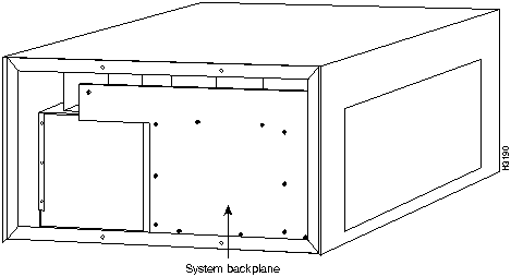
The high-speed backplane operates at 1.2 Gbps, the product of 25 MHz across the 48-bit wide bus. The backplane provides the connection between power supplies, supervisor engine module, interface modules, and backbone module. (See Figure 1-44.)
The backplane slots are numbered 1 through 5, with 1 at the top of the card cage and 5 at the bottom.
Figure 1-44 : Front View of the Catalyst 5000 Series Switch without Cover
The Catalyst 5000 series switch is equipped with one 376W, AC-input power supply. An optional second identical power supply is also available for fault-tolerant power. Dual power supplies are automatically load sharing and redundant, which means that a second power supply can be installed or replaced without interrupting system operation.
When two power supplies are installed and both are turned on, each concurrently provides about half of the required power to the system. If one of the power supplies fails, the second power supply immediately ramps up to full power to maintain uninterrupted system operation. Load sharing and fault tolerance are automatically enabled when the second power supply is installed; no software configuration is required.
Each power supply should be connected to a separate AC source so that, in case of an input power line or power supply failure, the second power supply maintains uninterrupted system power.
On the supervisor engine module faceplate, the PS1 LED goes on when the power supply in the left bay, labeled Power Supply 1 in Figure 1-15, is installed and supplying power to the system. The PS2 LED goes on when the power supply in the right bay, labeled Power Supply 2 in Figure 1-15, is installed and supplying power to the system. Both the LEDs should go on in systems with redundant power. Each AC-input power supply contains individual power switches.
When the PS1 or PS2 LEDs on the supervisor engine module are green, this indicates that the supply is turned on and receiving input AC power, and the output is within the specifications.
The PS1 and PS2 LEDs will be red if the power supply shuts down or there is no AC power input. The power supply may shut down automatically if it detects an out-of-tolerance temperature or voltage condition in the power supply. If the problem is eliminated, the PS1 and PS2 LEDs will go back to green.
The PS1 and PS2 LEDs will be off if the power supply is not installed.
The power supplies are self-monitoring. Each power supply monitors its own temperature and internal voltages. For a description of power-supply shutdown conditions and thresholds, refer to the section "Environmental Monitoring and Reporting" later in this chapter.
A modular power cord connects each power supply to the site power source. For power supply installation procedures, refer to the section "Installing and Replacing Power Supplies" in the chapter "Maintaining the Catalyst 5000 Series Switch."
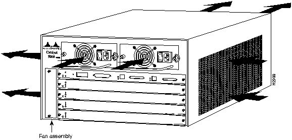
The system fan assembly provides cooling air for the supervisor engine module, interface modules, and backplane. The fan assembly is located inside the chassis compartment (see Figure 1-45).
An internal fan in each power supply draws cooling air from the rear of the chassis through the power supply and out the front of the chassis. (See Figure 1-45.) An air dam keeps the power-supply airflow separate from that of the rest of the chassis, which is cooled by the fan assembly.
Figure 1-45 : Internal Airflow
The fan assembly draws cool air from the right side of the chassis, when you are facing the rear of the chassis, to cool the modules. The exhaust air is forced out the left side of the chassis. Figure 1-45 shows the airflow path.
Sensors on the supervisor engine module monitor the internal chassis air temperatures. If the air temperature at the sensor exceeds a desired threshold, the environmental monitor displays warning messages. For specific threshold and status level descriptions, refer to the section "Environmental Monitoring and Reporting" later in this chapter. The fan assembly LEDs are shown and described in the section "Supervisor Engine Module LEDs" in the chapter "Confirming the Installation."
This section describes functions that support and maintain the Catalyst 5000 series switch. The hot-swapping feature for modules and redundant hot-swapping for power supplies enable you to quickly install new equipment without interrupting system power or shutting down interfaces. The environmental monitoring and reporting functions continuously monitor temperature and voltage points in the system, providing reports and warning messages that enable you to quickly locate and resolve problems and maintain uninterrupted operation. The redundant power option provides dual load-sharing power supplies. In the event of a power-supply failure or if one of two separate AC power sources fails, the redundant power option assures uninterrupted operation.
The five available interface slots support any combination of network interface modules or any of the same type modules to provide the following maximum port densities:
You can install any combination of modules in any of the four available module slots. There are no restrictions on either the number of modules that can be installed or their proximity to the supervisor engine module.
Each interface (or port) in the switch is designated by several different types of addresses. The physical interface address is the actual physical location (slot and port) of the interface connector within the chassis. The system software uses the physical addresses to control activity within the switch and to display status information. These physical slot and port addresses are not used by other devices in the network; they are specific to the individual switch and its internal components and software.
A second type of address is the MAC-layer address, which is a standardized data link layer address that is required for every port or device that connects to a network. Other devices in the network use these addresses to locate specific ports in the network and to create and update routing tables and data structures. The Catalyst 5000 uses a unique method to assign and control the MAC-layer addresses of its interfaces.
The following sections describe how the Catalyst 5000 switch assigns and controls both the physical (slot and port) and MAC-layer addresses for interfaces within the chassis.
Using Physical Interface Addresses
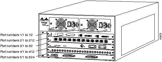
In the Catalyst 5000 switch, physical port addresses specify the actual physical location of each module port on the rear of the switch. (See Figure 1-46.) The address is composed of a two-part number in the format slot/port number. The first number identifies the slot in which the module is installed. Module slots are numbered 1 to 5 from top to bottom. The second number identifies the physical port number on the module. The port numbers always begin at 1 and are numbered from the left port to right port, facing the rear of the switch. The number of additional ports (n/1, n/2, and so on) depends on the number of ports available on the module.
Interface ports maintain the same address regardless of whether other modules are installed or removed. However, when you move a module to a different slot, the first number in the address changes to reflect the new slot number. For example, on a 12-port 100BaseTX switching module in slot 2, the address of the left port is 2/1 and the address of the right port is 2/12. If you remove the 12-port 10/100 Mbps Fast Ethernet Switching module from slot 2 and install it in slot 4, the addresses of those same ports become 4/1 and 4/12.
Figure 1-46 : Interface Port Address Examples
The supervisor engine is always n/1 to n/2, because it supports two interfaces---ports 1 and 2. Switching modules are always n/1 to n/12 because each switching module supports at least twelve interfaces. (Switching modules with more than 12 interfaces are addressed n/1 through n/n.).
You can identify module ports by physically checking the slot and port location on the back of the switch. You can also use software commands to display information about a specific interface, or all interfaces, in the switch. To display information about every interface, use the show port command without parameters. To display information about a specific interface, use the show port command with the interface type and port address in the format show port mod_num/port_num. If you abbreviate the command (sho po) and do not include parameters, the system interprets the command as show port and displays the status of all interfaces.
Following is an example of how the show port command without parameters displays status information (including the physical slot and port address) for each interface in the switch. In this example, most of the status information for each interface is omitted.
For complete command descriptions and instructions, refer to the Catalyst 5000 Series Configuration Guide and Command Reference.
All network interface connections (ports) require a unique MAC-layer address. Typically, the MAC address of an interface is stored on a component that resides directly on the interface circuitry. Each module has its own MAC address stored in a programmable read-only memory (EEPROM) on the module. Each VLAN in the spanning tree has one unique MAC addresses. The switch system code reads the EEPROM for each interface in the system, learns the MAC addresses, and can then initialize appropriate hardware and data structures.
This addressing scheme gives the switch the intelligence to identify the state (connected or notconnect) of each interface. When a module is hot-swapped, the MAC address changes with the module. The supervisor module also has a list of 1024 MAC addresses that it uses for multiple purposes, such as assigning unique identifiers for each VLAN spanning-tree bridge.
The hot-swapping feature allows you to install and replace modules while the system is operating; you do not need to disable the software, enter console commands, shut down the system power, or cause other software or interfaces to shut down. All modules support hot-swapping.
Environmental Monitoring and Reporting
The environmental monitoring and reporting functions enable you to maintain normal system operation by identifying and resolving adverse conditions before the system fails. Environmental monitoring functions constantly monitor the internal chassis air temperature. Each power supply monitors its own voltage and shuts itself down if it detects a critical condition within the power supply. The reporting functions enable you to retrieve and display the present values of measured parameters, and the reporting functions display alarms on the console if any of the monitored parameters exceed defined thresholds.
The environmental monitoring functions use three levels of status conditions to monitor the system. These levels are normal, alarm, and critical. The processor monitors the temperature inside the module compartment, and the power supplies use the normal and critical levels to monitor DC voltages. Table 1-1 lists temperature thresholds for the processor-monitored levels. Table 1-2 lists the DC power thresholds for the normal and critical power-supply-monitored levels.
Table 1-1 : Processor-Monitored Temperature Thresholds
Table 1-2 : Power-Supply-Monitored Voltage Thresholds
The three levels of status condition are as follows:
The processor uses the two levels of status conditions (normal and alarm) to monitor the air temperature in the module compartment. Sensors on the supervisor engine module monitor the temperature of the cooling air that flows through the module compartment. If the air temperature exceeds a defined threshold, the system processor indicates an alarm condition using the supervisor status LED, SNMP traps, and Command Line Interface displays. The processor stores the present alarm configuration for both temperature and DC voltage in nonvolatile memory (NVRAM). Information about these alarms can be retrieved later as a report of the last shutdown parameters.
If the temperature exceeds a defined threshold within a power supply, the power supply turns off. The Catalyst 5000 also shuts down if it contains only one power supply. However, if the Catalyst 5000 contains redundant power supplies, the switch shuts down only if both power supplies shut off.
The power supply monitors its own internal temperature and voltages. The power supply is either within tolerance (normal) or out of tolerance (alarm level), as shown in Table 1-2. If an internal power supply temperature or voltage reaches a critical level, the power supply shuts down without any interaction with the processor.
If the processor detects that AC input power is dropping but it is able to recover before the power supply shuts down, it logs the event as an intermittent power failure. The reporting functions display the cumulative number of intermittent power failures logged since the last power up.
This section describes the interaction of the system components that switch packets through the Catalyst 5000 series switch.
Figure 1-47 is a simplified block diagram of the system architecture and illustrates the general operation of the switch.
Figure 1-47 : Catalyst 5000 Series System Architecture
This section gives an overview of data transmission through the Catalyst 5000 series switch:
Management connections are provided to the network management processor using an EIA/TIA-232 interface console connection for remote (out-of-band) control and the
Copyright 1988-1996 © Cisco Systems Inc.
![]()
![]()

![]()
this chapter.) A detailed description of each LED is provided in the chapter "Confirming the Installation."
![]()


![]()






Console> show port help

Usage: show port

  show port <mod_num>

  show port <mod_num/port_num>
Console> (enable) show port

Port Name                 Status     Vlan       Level  Duplex    Speed Type

---- -------------------- ---------- ---------- ------ ------    ----- --------------

1/1  Management Port      notconnect 1          normal   half    100   100BaseTX

1/2  InterSwitchLink      connected  trunk      normal   half    100   100BaseTX

2/1  Dennis               connected  10         normal   a-half  a-10  10/100BaseTX

2/2  Luis                 notconnect 10         normal   auto    auto  10/100BaseTX

2/3  Iris                 notconnect 10         normal   auto    auto  10/100BaseTX

2/4  Nancy                connected  10         normal   a-half  a-10  10/100BaseTX

2/5  Arthur               notconnect 20         normal   auto    auto  10/100BaseTX

2/6  Ron                  notconnect 20         normal   auto    auto  10/100BaseTX

2/7  Connie               disabled   20         normal   auto    auto  10/100BaseTX

2/8  Bill                 notconnect 20         normal   auto    auto  10/100BaseTX

2/9                       notconnect 20         normal   auto    auto  10/100BaseTX

2/10                      notconnect 20         normal   auto    auto  10/100BaseTX

2/11                      notconnect 20         normal   auto    auto  10/100BaseTX

2/12                      notconnect 20         normal   full    10    100BaseTX


Port Align-Err  FCS-Err    Xmit-Err   Rcv-Err

---- ---------- ---------- ---------- ----------

1/1           0          0          0          0

1/2           1          0          0          0

2/1           0          0          0          0

2/2           0          0          0          0

2/3           0          0          0          0

2/4          30          0          0          0

2/5           0          0          0          0

2/6           0          0          0          0

2/7           0          0          0          0

2/8           0          0          0          0

2/9           0          0          0          0

2/10          0          0          0          0

2/11          0          0          0          0

2/12          0          0          0          0


Port Single-Col Multi-Coll Late-Coll  Excess-Col Carri-Sens Giants

---- ---------- ---------- ---------- ---------- ---------- ----------

1/1           0          0          0          0          0          0

1/2         680        418          0          1          0          -

2/1         756         99          0          0          0          0

2/2           0          0          0          0          0          0

2/3           0          0          0          0          0          0

2/4         409        403          0         11          0       1256

2/5           0          0          0          0          0          0

2/6           0          0          0          0          0          0

2/7           0          0          0          0          0          0

2/8           0          0          0          0          0          0

2/9           0          0          0          0          0          0

2/10          0          0          0          0          0          0

2/11          0          0          0          0          0          0

2/12          0          0          0          0          0          0


Last-Time-Cleared

--------------------------

Wed Apr 17 1996, 16:09:47

Console> (enable)
![]()
Parameter
Normal
Alarm
Ambient Airflow
< 45°C
> 45°C
Parameter
Critical
Normal
Critical
+5V
< 4.74V
4.74--5.26V
> 5.26V
+12V
< 11.40V
11.40--12.60V
> 12.60V
+24V
< 20.00V
20.00--30.00V
> 30.00V
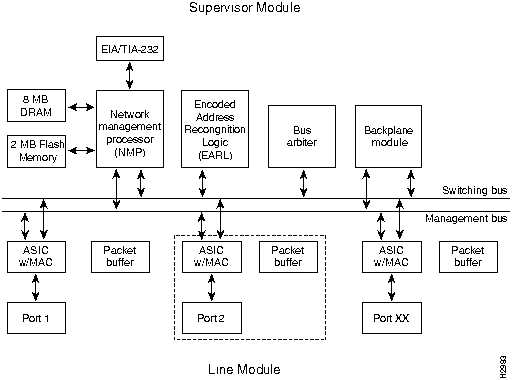
The ASIC is part of the port interface that includes a four-channel direct memory access (DMA) controller, MAC, CPU interface, and packet buffers. Each port has its own port interface.
packet bus for local (in-band) access. System software is stored for use by the network management processor in the 8 MB of DRAM and updated using the 4 MB of
Flash memory.
![]()
![]()
![]()
![]()
![]()
![]()
![]()
![]()