|
|
Installing Cisco 700 Series Routers
This chapter describes the procedure for installing the Cisco 700 series router and contains the following sections:
You will need the following to install a Cisco 700 series router:
The Cisco 700 series routers can be placed on any flat, secure surface. They are designed to operate without requiring cooling fans or special equipment closets or racks.
This section describes how to connect your router to the LAN network and the WAN network.
Table 3-1 lists the installation procedure step that you should being with, based on your LAN connection type.
Table 3-1 : First Installation Step Based on LAN Connection Type
| Cisco 750 series router to 10Base2 Ethernet | Step 1 |
| Cisco 760 series router to 10Base5 Ethernet | Step 3 |
| Any Cisco 700 series router to 10Base T Ethernet | Step 5 |
Table 3-2 : 10BaseT Port Labels
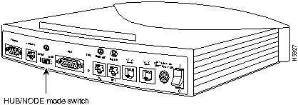
Figure 3-1 illustrates the HUB/NODE switch, located on the rear panel of the Cisco 760 series routers.
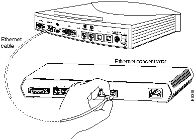
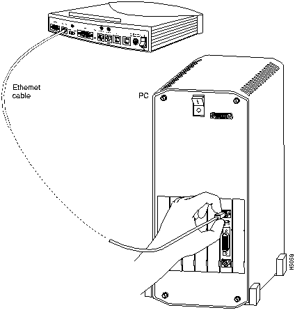
Figure 3-1 : HUB/NODE Switch (Cisco 766 Shown) Figure 3-2 : 10BaseT to Ethernet Concentrator Connection (Cisco 766 Shown) Figure 3-3 : 10BaseT Cable to PC NIC Connection (Cisco 766 Shown) Table 3-3 : ISDN BRI Port Labels
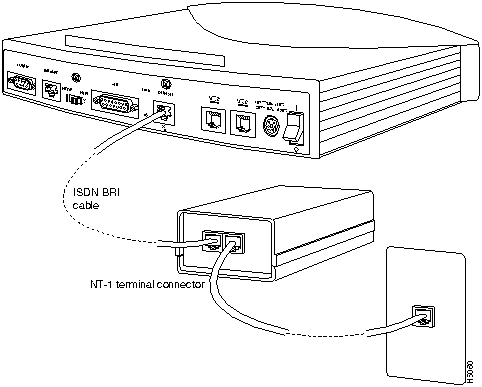
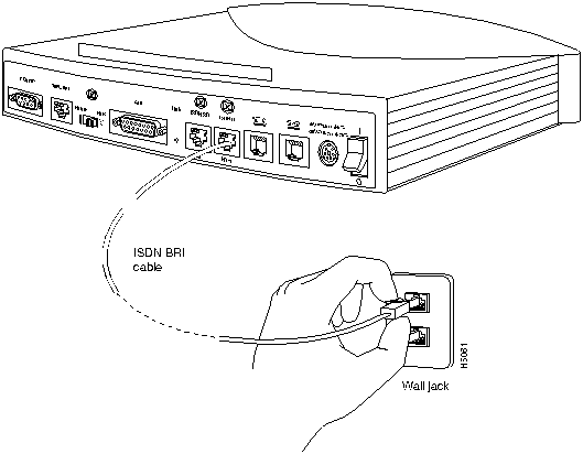
Figure 3-4 : ISDN BRI Cable to NT-1 Connection (Cisco 765 Shown) Figure 3-5 : ISDN BRI Cable to ISDN BRI Wall Jack Connection (Cisco 766 Shown) Take the following steps to connect the Cisco 700 series router to a console:
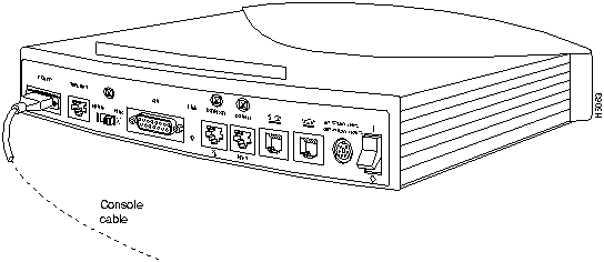
Figure 3-6 : Console Cable to Router Connection (Cisco 766 Shown) Your Cisco 700 router ships with either a wall-mounted or desktop power supply. The wall-mounted power supply is used with the Cisco 751 and Cisco 752, and the desktop power supply is used with the Cisco 753 and all Cisco 760 series routers. This section explains how to connect both types of power supplies.
Connecting the Wall-Mount Power Supply
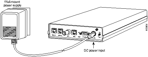
The wall-mount power supply is used with the Cisco 751 and Cisco 752. Connect the wall-mount power supply as follows:
Figure 3-7 : Wall-Mount Power Supply Connection (Cisco 752 Shown) Connecting the Desktop Power Supply
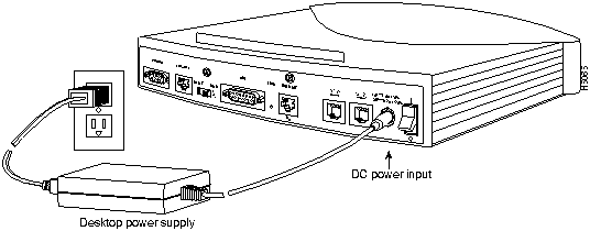
The desktop power supply is used with the Cisco 753 and all Cisco 760 series routers. Take the following steps to connect the desktop power supply:
Figure 3-8 : Desktop Power Supply Connection (Cisco 765 Shown) Basic installation of the Cisco 700 series router is complete. Depending on which model you are using, you can also connect an ISDN telephone (a telephone that operates over ISDN telephone lines), an analog device, such as a telephone or modem, or both to your router. For instructions on how to connect an ISDN telephone or analog device, see the following two sections, "Connecting an ISDN Telephone" and "Connecting an Analog Telephone Device."
If you are using the Cisco 752, Cisco 753, Cisco 762, or Cisco 766, you can connect an ISDN telephone to the router. The ISDN telephone uses the same ISDN line that the router uses.
Connecting a Self-Powered ISDN Telephone
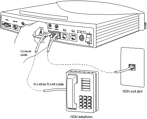
To connect the ISDN telephone to the router, connect the ISDN telephone cable (provided with the ISDN telephone) to the RJ-45 port labeled ISDN S/T on the rear panel of the router, and connect the telephone wall jack to the port labeled ISDN U, as shown in Figure 3-9.
You can connect an ISDN telephone to the Cisco 751, Cisco 761, or Cisco 765 through an external NT-1 connector only.
Figure 3-9 : ISDN Telephone to Router Connection (Cisco 766 Shown) Connecting an ISDN Telephone and External Power Supply
This section describes an example procedure of how to connect the router to an ISDN telephone that requires an external power supply.
This example procedure describes how to connect an AT&T ISDN telephone (model ISDN 8510T) and an AT&T external power supply (model MSP-1) that supplies power to this telephone. Depending on the ISDN telephone model and power supply model that you use, the procedure to connect the ISDN telephone and power supply might differ slightly.
For information on ISDN U port pinouts, refer to Table D-1 in the appendix "Cabling Specifications for Cisco 700 Series Routers."
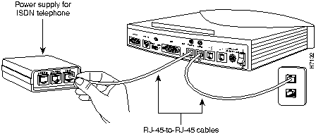
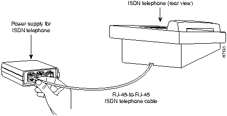
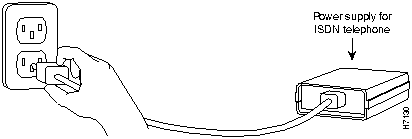
Take the following steps to connect the ISDN telephone and external power supply:
Figure 3-10 : ISDN Telephone Power Supply to Router Connection (Cisco 766 Shown) Figure 3-11 : ISDN Telephone to Power Supply Connection Figure 3-12 : ISDN Telephone Power Supply to Power Outlet Connection You can now use the ISDN telephone on the same ISDN line as the router.
Connecting an Analog Telephone Device
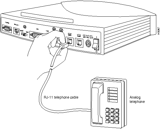
If you are using a Cisco 753, Cisco 765, or Cisco 766, you can connect one or two analog devices, such as a telephone, fax machine, or modem, directly to the unit. The analog device is connected to basic telephone services through the ISDN line that the router uses.
To connect the analog device to the router, connect the telephone cable (provided with the analog device) to the RJ-11 port (labeled PHONE on the Cisco 753 and with a telephone icon on the Cisco 765 and Cisco 766) on the rear panel of the router, as shown in Figure 3-10.
Figure 3-13 : Analog Telephone to Router Connection (Cisco 766 Shown)
Copyright 1988-1996 © Cisco Systems Inc.
Step 7.
Model
Label
Cisco 751
10BASET
Cisco 752 and Cisco 753
10BT
Cisco 760 series, all models
10BaseT
![]()
Model
Label
Cisco 751
LINE
Cisco 752, Cisco 753, Cisco 762, and Cisco 766
ISDN U
Cisco 761 and Cisco 765
ISDN S/T
Model
Interface
Cable
Cisco 750 Series
ISDN U
Use RJ-11-to-RJ-11
Cisco 760 Series
ISDN U
Use RJ-11-to-RJ-45
Cisco 750 Series and Cisco 760 Series
ISDN S/T
From ISDN wall jack to the NT1---Use either RJ-11-to-RJ-11 or RJ-45-to-RJ-45
From NT1 to router's ISDN interface---Use RJ-45-to-RJ-45
![]()
![]()
![]()
![]()
![]()
![]()
![]()
![]()
![]()
![]()
![]()
![]()