Table of Contents
Installing the Cisco 7513
Installing the Cisco 7513
This chapter includes procedures for rack-mounting and installing the Cisco 7513.
To rack-mount the Cisco 7513 (which is an optional but recommended installation because of chassis size and weight), refer to the document Cisco 7513 Rack-Mount Kit Installation Instructions, which is available on Cisco Connection Documentation CD-ROM or as a printed copy (Document Number 78-2023-xx, where xx is the latest version).
Note If you choose not to rack-mount the Cisco 7513, refer to the section "General Installation."
Warning To prevent bodily injury when mounting or servicing this unit in a rack, you must take special precautions to ensure that the system remains stable.

The following guidelines are provided to ensure your safety:
- This unit should be mounted at the bottom of the rack if it is the only unit in the rack.
- When mounting this unit in a partially filled rack, load the rack from the bottom to the top with the heaviest component at the bottom of the rack
- If the rack is provided with stabilizing devices, install the stabilizers before mounting or servicing the unit in the rack.
For translated versions of this warning, refer to the appendix "Translated Safety Warnings."

Caution To maintain a low center of gravity in a rack with a single Cisco 7513 chassis, the chassis bottom should be no higher than 20 inches above the floor. To prevent tipping the chassis when moving it, do not use a ramp inclined at more than 10 degrees.
The chassis should already be in the area where you will install it, and your installation location should already be determined.

Warning Before working on a chassis or working near power supplies, unplug the power cord on AC units or disconnect the power at the circuit breaker on DC units. (For translated versions of this warning, refer to the appendix "Translated Safety Warnings.")
When installing the chassis on a table or the floor, ensure that you have planned a clean, safe location for the router and have considered the following:
- The location does not block the chassis intake (rear) and exhaust (front) vents.
- Multiple chassis can be placed side by side; however, we recommend that you do not stack chassis one on top of the other, outside of an equipment rack.
- Dust accumulates on floors. If you are placing the chassis on the floor, try to find a location with a minimum of dust. Make sure that the area in which you will install the chassis is free of debris and dust. Also make sure your path to the area is unobstructed.
- A raised platform or sturdy table is a cleaner environment than the floor.
- A temperature-controlled, air-conditioned area is ideal for the chassis.
- When you are deciding where to install any equipment, consider future maintenance requirements. Allow at least two or three feet of clearance behind the power supplies for maintenance (installing or replacing power supplies, blower module, or interface processors).
- Up to two power supplies are shipped with the chassis, but are not installed. We recommend that you install the power supplies after you position (or rack mount) the chassis.
- The Cisco 7513 chassis weighs 160 pounds (72.6 kg) fully configured and can be lifted by two people; however, to make the installation easier, consider removing components from the chassis.
- Specifically, consider the following:
- Each processor module weighs approximately 2.5 pounds (1.13 kg).
- (Refer to the section "Removing and Replacing Processor Modules" in the chapter "Preparing for Installation.")
- The card cage assembly weighs approximately 15 pounds (6.8 kg).
- (Refer to the section "Removing and Replacing the Card Cage Assembly.")
- The blower module weighs approximately 10 pounds (4.55 kg).
- (Refer to the section "Removing and Replacing the Blower Module.")
- Each power supply weighs approximately 25 pounds (11.34 kg).
- (Refer to the section "Installing the Power Supplies.")
- To lighten the chassis by approximately 110 pounds (49.9 kg), remove the power supplies, processor modules (assuming all thirteen slots are filled), card cage assembly, and blower module before moving the chassis into the rack. (We recommend removing all of these items for rack-mount installation.)
- To lighten the chassis by approximately 100 pounds (40.8 kg), remove the power supplies, processor modules (assuming all thirteen slots are filled), and card cage assembly before moving the chassis into the rack.
- To lighten the chassis by approximately 85 pounds (38.6 kg), remove only the power supplies and processor modules before moving the chassis into the rack.
- To lighten the chassis by approximately 50 pounds (22.7 kg), remove only the power supplies before moving the chassis into the rack.

Warning Two people are required to lift the chassis. Grasp the chassis underneath the lower edge and lift with both hands. To prevent injury, keep your back straight and lift with your legs, not your back. To prevent damage to the chassis and components, never attempt to lift the chassis with the handles on the power supplies, interface processors, or the blower module. These handles were not designed to support the weight of the chassis. (For translated versions of this warning, refer to the appendix "Translated Safety Warnings.")
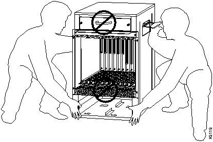
To prevent damage to the chassis, lift the chassis by placing one hand on a side handle and the other beneath the front of the chassis, as shown in Figure 3-1.
Figure 3-1 Lifting the Cisco 7513

Note Do not lift the chassis using the blower module handle or the air intake vent.
On the rear of the chassis, do the following:
- Step 1 The chassis is shipped with processor modules installed. You can install the chassis with the processor modules installed in the chassis; however, if you want to remove them to make the installation easier, refer to the procedures in the section "Removing and Replacing Processor Modules," in the chapter "Preparing for Installation."
- Step 2 We recommend that you also remove the card cage assembly to make the chassis easier to move, but this is not required. If you want to remove the card cage assembly, refer to the section "Removing and Replacing the Card Cage Assembly."
- Before removing the card cage assembly, both power supply bays must be empty. One or two power supplies are shipped with the chassis, but are not installed. Also, remove all power supply blanks before you remove the card cage assembly.
- Step 3 In systems with one power supply, ensure that power supply bay A is empty and that power supply bay B has a power supply blank installed. In systems with two power supplies, ensure that both power supply bays are empty.
- Step 4 Two people are required to perform this step. Standing on each side of the chassis, grasp the side handle with one hand and with the other hand, grasp the chassis underneath the lower edge and lift with both hands. Slowly lift the chassis in unison.
- Avoid sudden twists or moves to prevent injury. To prevent damaging the air intake vent below the card cage opening, do not grasp the chassis below the air intake vent.
- Step 5 Place the chassis in a location where the air intake vent is not drawing in exhaust air from other equipment.
- Ensure that you temporarily have at least two to three feet of clearance around the rear of the chassis. You will need this space to install the power supplies, perform maintenance on the chassis, and observe LED indications. After installation, this space can be reduced as required; however, maintain a minimum of 19 inches (48.3 cm) behind the chassis.
- Step 6 Using the procedures in the section "Removing and Replacing Processor Modules," in the chapter "Preparing for Installation," replace the processor modules in the chassis.
- Step 7 Check all ejector levers and ensure the processor modules are securely installed.
- Step 8 Check the captive installation screws on the processor modules and tighten any that are loose.
- Step 9 After you position the chassis (and replace the card cage assembly and blower module if you removed them for the chassis installation), you can insert the power supplies. Refer to the section "Installing the Power Supplies."
The card cage comprises one assembly that includes the card cage and backplane. The assembly slides into and out of the chassis and attaches to the chassis frame with four slotted, captive screws. For this procedure, you will need one large flat-blade screwdriver, and the board racks, which are recommended and provided with the original packing material.
This procedure requires that all processor modules first be removed from the card cage. To remove them, refer to the section "Removing and Replacing Processor Modules," in the chapter "Preparing for Installation."
Following is the procedure for removing the card cage assembly, which cannot be removed with power supplies or power supply blanks installed:
- Step 1 Remove all processor modules from the chassis card cage according to the procedures in the section "Removing and Replacing Processor Modules," in the chapter "Preparing for Installation."
- Make a note of the processor module slots as you remove them. Do not stack the processor modules one on top of another. It is possible to remove the card cage from the chassis with the processor modules installed; however, it is not recommended. Thirteen processor modules add 32.5 pounds (14.7 kg).
 Caution Unless the chassis is mounted in a rack, or otherwise anchored, the chassis might move toward you when you pull the card cage and backplane assembly in the following step. To prevent injury, have a second person hold the chassis in place while you pull the card cage and backplane assembly from the chassis.
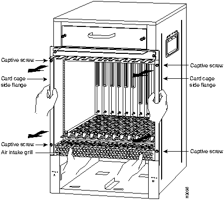
- Step 2 With the processor modules and power supplies removed, loosen the four large captive screws located on the card cage flanges, to the left and right of the card cage opening, as shown in Figure 3-2.
Figure 3-2 Removing the Chassis Card Cage

- Step 3 With the captive screws loosened, carefully grasp the intake grill with both hands, and pull the card cage assembly straight out of the chassis until there is enough clearance at the card cage side flanges to pull the entire assembly clear of the chassis sides, as shown in Figure 3-2. The assembly is heavier at the backplane and might be awkward to handle.
- Step 4 When the card cage and backplane assembly is completely free of the chassis, carefully place it on an antistatic mat or foam.
 Caution The electronic components on the rear of the backplane are completely exposed when the card cage and backplane assembly is removed from the chassis. To prevent damaging these components, place the card cage and backplane assembly on an antistatic mat or foam, and place the assembly in the same orientation as when it is mounted in the chassis.
- Step 5 To replace the card cage and backplane assembly, carefully lift the assembly, place it into the chassis opening, and slide the assembly into the chassis opening until the left and right card cage flanges are flush with the chassis flanges.
- Step 6 Press the card cage and chassis flanges together and tighten each captive screw. Do not overtighten the captive screws.
 Caution The electronic components on the rear of the backplane are completely exposed when the card cage and backplane assembly is removed from the chassis. To prevent damaging these components, carefully slide the assembly into the chassis opening.
- Step 7 Replace all the processor modules you removed earlier. Use the notes you made in Step 1 to reinstall the processor modules in the correct slots.
When viewing the chassis from the noninterface processor end, the blower module is located above the card cage, as shown in Figure 1-1. Two slotted captive screws hold the blower module in place. For this procedure, the system should not be on. Follow these steps to remove and replace the blower module.
- Step 1 Locate the blower module, which is above the card cage on the noninterface processor end of the chassis, as shown in Figure 1-1.
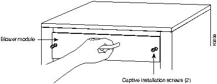
- Step 2 Use a flat-blade screwdriver to loosen the captive screws that fasten each end of the blower module, as shown in Figure 3-3.
Figure 3-3 Removing the Blower Module

- Step 3 Grasp the handle on the front of the module and slowly pull it straight out of the chassis, as shown in Figure 3-3.
- Step 4 To replace the blower module, refer to Figure 3-3, and hold the blower handle with either your right or left hand (as long as you use both hands to handle the module). With the intake vents on the blower module facing down and the "Insert This Side Up" label facing up, insert the module into the chassis opening. Keep the module as straight as possible as you guide it into the chassis.
- Step 5 When the blower is all the way into the chassis opening, tighten the captive installation screws on the front of the blower module.
This completes the blower module removal and replacement procedure.
Use the following steps to install the cable-management bracket on the router. You will need a large, flat-blade screwdriver for this procedure.
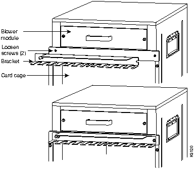
- Step 1 At the interface processor end of the router, locate the two slotted screws located between the blower module and the card cage. (See Figure 3-4.)
- Step 2 Using a flat-blade screwdriver, loosen these two screws.
- Step 3 Place the bracket over the screws, as shown in Figure 3-4.
Figure 3-4 Installing the Cable-Management Bracket

- Step 4 Use the flat-blade screwdriver to tighten the screws.
- Step 5 When you install the network interface cables, route the cables to and through the cable-management bracket. If you are using very thin cables that slip through the bracket openings, insert cable ties through the holes in the bracket and wrap them around the cables to secure them.
Note It might be necessary to bundle longer cables to avoid tangling them. Do this at the cable-management bracket or at the rack, but leave enough room to remove processor modules and power supplies and to change cables as required. Do not block the power supply or chassis intake air vents with cables. Verify that the cables do not interfere with removal and installation of the blower module.
This completes the procedure for installing the cable-management bracket.
The Cisco 7513 can be used with up to two AC-input or DC-input power supplies for redundant power.

Caution Mixing AC-input and DC-input power supplies in the same Cisco 7513 is not a supported configuration and should not be attempted. Doing so might cause damage.
The chassis is shipped with power supplies packaged separately. To properly insert the power supplies and connect power, refer to the following accompanying documentation:
Both of these documents are available on Cisco Connection Documentation CD-ROM or as printed copies.
Copyright 1988-1996
©
Cisco Systems Inc.
![]()
![]()
![]()
![]()

![]()

![]()
![]()


![]()