|
|
Cisco 7513 Rack-Mount Kit Installation Instructions
Product Number: ACS-7000RMK(=)
This document provides instructions for installing a Cisco 7513 chassis in a 19-inch rack and a Telco rack. For complete system installation and startup procedures, refer to the Cisco 7513Hardware Installation and Maintenance publication.
The sections in this document include the following:
![]()
This section describes the types of racks for which this rack-mounting kit is intended, and the mounting configurations that are possible with each type.
The rack-mount kit, Product Number ACS-7000RMK(=), is suitable for mounting the chassis in most 19-inch 2-post, 4-post, or Telco-type racks.
The rack must have at least two mounting posts on which to mount the hardware, and the distance between the mounting holes in the two posts must be 18.31 inches ± .063 inches (as specified in the specification Electronic Industries Association (EIA)--310-C).
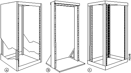
Figure 1 shows the three types of equipment racks described in this document:
Figure 1 : Equipment Rack Types
Rack-Mount Installation Summary
Following is a summary of the installation procedures required to rack-mount the chassis. This summary is informational and is not intended to replace the actual procedures required to rack-mount the chassis.
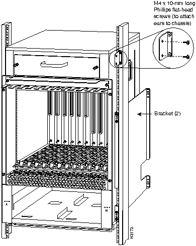
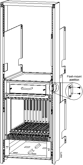
Throughout these installation procedures, refer to Figure 2, Figure 3, and Figure 4, in addition to the illustrations provided in the specific procedures.
The mounting kit comprises two brackets, two chassis ears (each holds two captive grommets), and fasteners (screws). On each bracket, the inner side has a turned ledge at the bottom to support the chassis, and non-conductive material to provide electrical isolation between the chassis and the rack. At the front of each bracket is a flange with five mounting holes at the top and three at the bottom.
Table 1 lists the parts that are included in the rack-mount kit. To verify that you received all the parts listed, refer to Table 1 and to Figure 2 on page 5. If any parts are missing, contact a service representative for assistance. (Refer to the section "Cisco Information Online" at the end of this document.)
Table 1 : Rack-Mount Kit Parts Checklist
| Quantity | Part Description | Received |
|---|---|---|
| 2 | Mounting brackets (left and right are identical), each with an attached spanner bar | |
| 2 | Chassis ears with captive grommets (left and right ears are identical) | |
| 4 | M4 x 10-mm LG Phillips flat-head screws | |
| 12 | 10-32 x LG Phillips pan-head screws with integral square cone washers |
Each of the two brackets mounts to a rack post with four 10-32 x 5/8-inch, Phillips pan-head screws, which are provided. The front of each bracket attaches to the front of the rack post, and the remainder of the bracket cantilevers off the post. A ledge at the bottom of each bracket provides a shelf for the bottom edges of the chassis.
A spanner bar on each bracket hooks into the opposite bracket to maintain an exact distance between the two brackets at both the ends attached to the rack posts and unattached ends. Spanner bars prevent the two brackets from separating. (See Figure 11 on page 20.)
Figure 2 shows the components in the rack-mount kit.
Figure 2 : Rack-Mount Kit Components
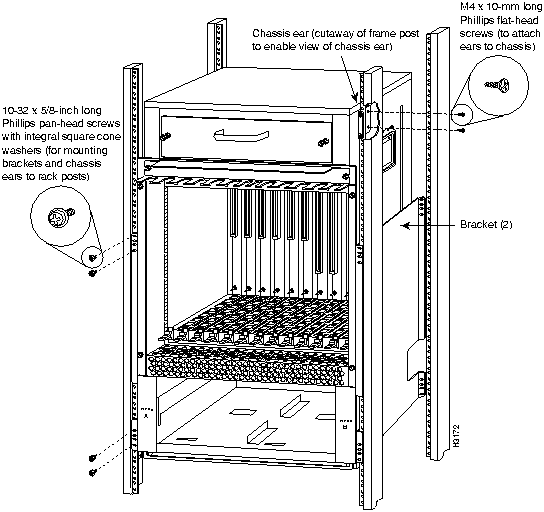
One chassis ear attaches to each side of the chassis with two M4 x 10-mm, Phillips flat-head screws. When the chassis is in the rack, the mounting strips on the chassis ears attach to the rack-mounting posts with four 10-32 x 5/8-inch, Phillips pan-head screws (two for each ear).
The ledges at the bottom of the brackets support the weight of the chassis. The ears are not weight-bearing fixtures, but prevent the chassis from sliding out of the rack horizontally.
In Telco-type installations, you can install the chassis so that the ends of the chassis are approximately centered on two posts. The chassis ears can be turned around to prevent the chassis from sliding horizontally. Figure 3 shows a typical center-mount installation.
Figure 3 : Typical Center-Mount (Telco-Type) Installation
In a two-post, four-post, or Telco-type installation, you can flush-mount the chassis so that the end of the chassis is flush with the rack posts. Figure 4 shows a typical flush-mount installation.
Figure 4 : Typical Flush-Mount Installation (For Telco Racks Bolted to the Floor)
Before you begin this installation, review the safety guidelines in this section to avoid injuring yourself or damaging the equipment. This section also provides descriptions of the tools and parts you need to perform this installation, and guidelines for planning the rack location so that you can access the system components when necessary and maintain trouble-free operation.
If you are mounting a chassis that is already installed, you will need to disconnect all power and interface cables from the back of the chassis. Be sure to label the cables to avoid confusion when you reconnect them to the interface ports. The configuration worksheet provided near the end of this document can help you reconnect the cables to the correct ports. Make a copy of the worksheet and complete it as you disconnect cables from the chassis. (See Figure 25 and Table 2 on page 38.)
Review the following guidelines to help ensure your safety and protect the equipment from damage during the installation.
The Cisco 7513 chassis weighs 50 pounds (22.7 kilograms [kg]) when empty (with no interface processors, card cage, blower module, or power supplies installed) and 160 pounds (72.58 kg) with two power supplies and thirteen processor modules installed. The chassis is not intended to be moved frequently.
Before you install the router, ensure that your site is properly prepared, so you can avoid having to move the chassis later to accommodate power sources and network connections.
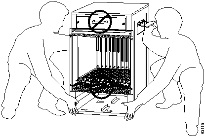
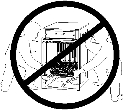
Whenever you lift the chassis or any heavy object, follow these guidelines:
Figure 5 : Correct Way to Lift the Chassis
Figure 6 : Incorrect Way to Lift the Chassis
Follow these basic guidelines when working with any electrical equipment:
When you replace the power supplies, remember to engage all of the safety features on each power supply. The power supplies feature the following three safety interlock features:
For a complete description of the power supply, refer to the Cisco 7513 Hardware Installation and Maintenance publication.
Working with Electrical Equipment
When working with any electrical equipment, the following guidelines will help to ensure your safety and protect the equipment. This list does not include all potentially hazardous situations, so be alert.
The rack-mount kit is suitable for mounting the Cisco 7513 in most 19-inch two-post, four-post, or Telco-type racks that conform to the EIA-310-C specification. The brackets, which support the chassis, cantilever off two rack posts. You can then mount the chassis with either end approximately flush with the two rack posts, or, in Telco-type installations, you can center-mount the chassis.
Before proceeding, review the guidelines in this section. Ensure that you have planned your installation carefully. Avoid hazards such as top-heavy or unbalanced racks, or cables or equipment that obstruct traffic paths and access to equipment.
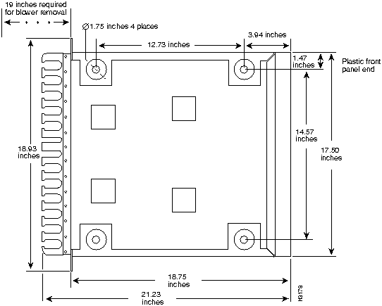
Figure 7 shows the chassis footprint and outer dimensions, and the clearance required to remove or install power supplies, processor modules, and the blower module.
Figure 7 : Cisco 7513 Chassis Footprint and Outer Dimensions
Planning a proper location for the router and the layout of your equipment rack is essential for successful system operation. Equipment placed too close together or inadequately ventilated can cause overtemperature conditions inside the chassis. In the Cisco 7513, the cooling air is drawn in through the rear of the chassis, and the exhaust air is forced out the front through the panel vent.
The following guidelines are recommended to ensure a sufficient flow of cooling air to the chassis:
For complete site requirements and recommendations, refer to the Cisco 7513 Hardware Installation and Maintenance publication.
When installing one chassis in any rack that is not secured to the floor or overhead structure, place the chassis in the lower half of the rack. A fully configured Cisco 7513 weighs 160 lbs (72.58 kg), and a shift in the weight distribution (during the installation or later) can cause the rack to fall.
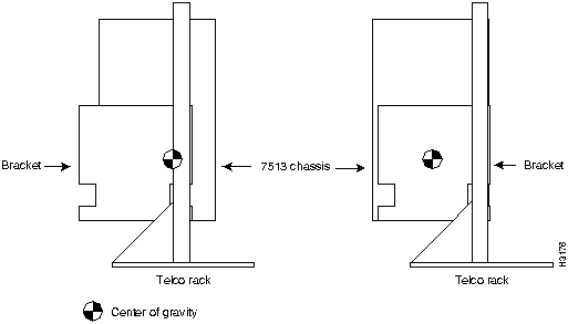
Also, when installing the chassis in Telco-type racks, ensure that the rack is secured to the floor or otherwise stabilized. Center-mount the chassis if possible (and practical for your installation). Doing so places the center of gravity closest to the center of the mounting posts. Figure 8 shows the center of gravity for both center-mounted and flush-mounted installations. (The center of gravity will shift somewhat depending on which end of the chassis is positioned at the front of the rack.)
Figure 8 : Chassis Center of Gravity for Telco Rack Configurations
Rack Dimensions and Site Layout
To help maintain trouble-free operation, consider the following precautions when planning your rack installation:
This section lists the tools you will need to complete this installation and the parts that are shipped as part of the rack-mount kit. Ensure that you have all the tools and parts required so that you can complete the installation without interruption.
You will need the following tools to install the mounting hardware and chassis in the rack:
You also need the following tools to replace the power supplies after mounting the chassis:
Before beginning the power supply installation, check the captive installation screws on all power supplies to determine which tools you will need.
The following sections describe the procedures for mounting the chassis in a 19-inch equipment rack with two or four mounting posts or a Telco-type rack.
Before proceeding, review the guidelines and recommendations in the section "Prerequisites" on page 8 to protect your safety, to maintain sufficient clearance around the rack during and after the installation, and to ensure proper airflow through the chassis after the installation.
Some equipment racks provide a power strip along the length of one of the rear mounting strips. If your rack has this feature, we recommend that you fasten the brackets and install the interface processor end of the chassis at the opposite side of the rack.
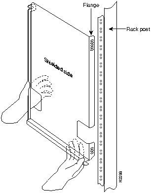
The two brackets provided in the rack-mounting kit are identical. The inner side of each bracket has a ledge at the bottom to support the undersides of the chassis, and shielding to provide electrical isolation between the chassis and the rack. A flange on the front of each bracket provides five mounting holes at the top, and three at the bottom. Mount the bracket with the flange in front of the rack post, and with the inner (shielded) side facing the center of the rack. The ledge should be at the bottom of the bracket. (See Figure 9.) To maintain a low center of gravity, mount the brackets in the rack at the lowest point as possible.
Figure 9 : Positioning a Bracket
The cutouts in the brackets are to accommodate the ear brackets that fasten the Cisco 7000 chassis to the rack. The chassis ears mount farther up on the Cisco 7513 chassis.
Mounting the Brackets to the Rack Posts
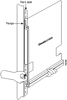
Follow these steps to mount each bracket to a rack post:
Figure 10 : Installing a Bracket on a Rack Post (Left Bracket Shown)
To position and secure the spanner bars, proceed to the next section.
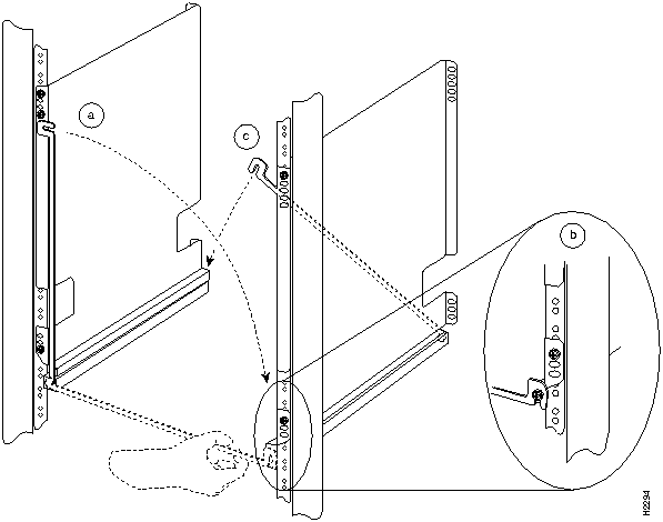
The spanner bar on each bracket hooks into the opposite bracket to maintain a fixed spacing between the two brackets. The spanner bars prevent the brackets from separating or drifting apart, particularly at the bracket ends that are not secured to the rack.
Follow these steps to secure the spanner bars:
Figure 11 : Positioning and Fastening a Spanner Bar
This completes the bracket installation.
To install the ears on the chassis, proceed to the next section.
The ears attach directly to the chassis with four M4 x 10-mm, flat-head screws (two on each side).
Attach the ears to the chassis before you slide the chassis onto the brackets and into the rack. After you slide the chassis into the rack, insert a 10-32 x 5/8-inch pan-head screw through each of the captive grommets on the ears and through the rack-mounting strips.
The ears do not bear the weight of the chassis, but prevent it from walking, or sliding horizontally out of the rack.
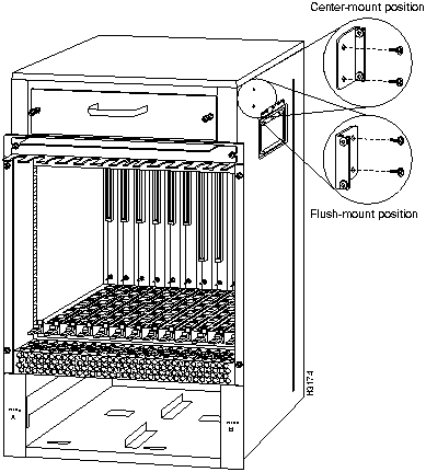
In Figure 12, inserts on the right show how the ears attach to the chassis for center mounting and flush mounting.
Figure 3, on page 6, shows a typical center-mount installation and Figure 4, on page 7, shows a typical flush-mount installation.
In some Telco-type racks, it is more practical to center-mount the chassis. To do so, flip the ears around so that the mounting strips are near the center of the side of the chassis. In Figure 12, the upper insert on the right shows how the ears attach to the chassis for center mounting.
Figure 12 : Installing the Ears on the Chassis
Follow these steps to install the ears on the chassis:
Proceed to the next section to install the chassis in the rack.
Preparing the Chassis and Installing the Chassis in a Rack
Two people are required to lift the chassis and complete this part of the installation.
You will need to lift the chassis and slide it into the rack and onto the ledges provided by the brackets. After you push the chassis back into the rack, you will attach the ears to the rack-mounting strips to prevent the chassis from sliding forward or backward out of the rack.
Before moving the chassis, we recommend that you disconnect all power and interface cables and that you remove both power supplies and all processor modules.
Removing the card cage assembly and blower module is recommended before installing the chassis, but is not required; their combined weight is approximately 25 pounds.
If you choose not to remove the power supplies, processor modules, blower module, and card cage assembly, consider the following:
Removing Power Supplies, Blower Module, and the Card Cage Assembly
Before you remove the card cage assembly, you must remove the power supplies.
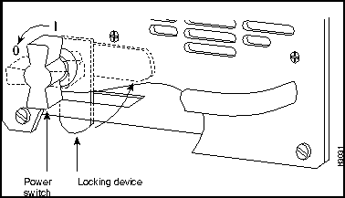
On AC-input and DC-input power supplies, a power switch with a locking mechanism prevents the power supply from being removed from the chassis when the power supply switch is in the ON (|) position. (See Figure 13.) When the switch is on, a metal tab extends into a slot in the chassis. When the switch is OFF (O), the tab is raised and clears the slot.
For the DC-input power supply, you must provide two nylon cable ties for cable strain relief. Replace the strain relief with new nylon cable ties after you replace the DC-input power supply. In addition to a large slotted screwdriver, you also need a pair of wire cutters for this procedure.
Figure 13 : Power Switch Locking Mechanism for Power Supplies
Order of Procedures
If you have AC-input power supplies, refer to the following sections:
If you have DC-input power supplies, do the following:
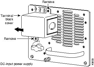
Removing DC-Input Power Supplies Follow these steps to remove a DC-input power supply.
Figure 14 : Removing and Replacing the Terminal Block Cover
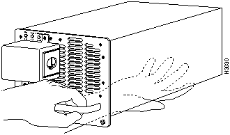
Figure 15 : Removing a DC-Input Power Supply
Figure 16 : Supporting the DC-Input Power Supply
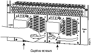
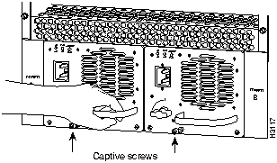
Removing AC-Input Power Supplies Follow these steps to remove an AC-input power supply.
Figure 17 : Removing and Replacing an AC-Input Power Supply
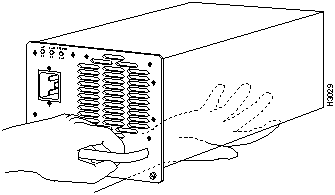
Figure 18 : Supporting the AC-Input Power Supply
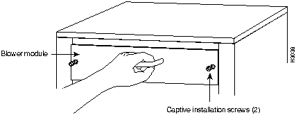
Removing the Blower Module When viewing the chassis from the noninterface processor end, the blower module is located above the card cage (See Figure 19.) Two slotted captive screws hold the blower module in place.
Follow these steps to remove and replace the blower module.
Figure 19 : Removing and Replacing the Blower Module
This completes the blower module removal procedure.
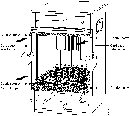
Removing the Card Cage Assembly The card cage consists of one assembly that includes the card cage and backplane, which can be removed and replaced as required. There are no wires, harnesses, or connectors. The assembly slides into and out of the chassis and attaches to the chassis frame with four slotted, captive screws. (See Figure 21.)
For this procedure, you will need one large flat-blade screwdriver, an antistatic bag for each removed processor module, or several antistatic mats or pieces of antistatic foam.
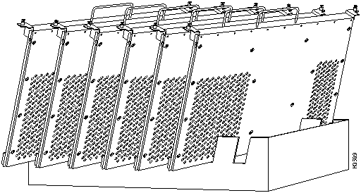
Temporarily place removed processor modules in the collapsible, black-cardboard board racks that were provided with your packing material, as shown in Figure 20.
Figure 20 : Board Rack with Processor Modules
Following is the procedure to replace the card cage and backplane assembly:
Figure 21 : Removing and Replacing the Card Cage and Backplane Assembly
Moving the Chassis into the Rack
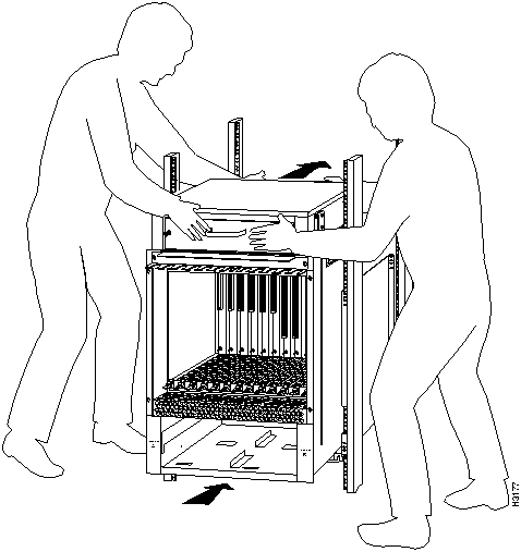
Two people are required to lift the chassis and insert it into the rack.
The chassis weighs approximately 75 pounds (34.02 kg) when the power supplies and processor modules are removed. Make sure that your path to the rack is not obstructed.
You will insert the front end of the chassis into the rack, lower it onto the two ledges on the brackets, and then slide the chassis back until the ears meet the rack-mounting posts.
Follow these steps to install the chassis in the rack:
Figure 22 : Sliding the Chassis into the Rack (Shown with Card Cage Assembly and Blower Installed)
This completes the procedure for moving the chassis into the rack.
The inner sides of the mounting brackets and the grommets on the chassis ears are shielded to isolate the chassis from contact with the equipment rack. If your installation requires that the chassis be electrically isolated from the rack, ensure that there are no conductive contact points between the chassis and the rack before replacing the power supplies.
Use an ohmmeter to perform the following test:
If you removed the blower module, proceed to the section "Replacing the Blower Module."
If you did not remove the blower module, proceed to the section "Replacing the Card Cage Assembly" on page 34, and then to the section "Replacing DC-Input Power Supplies" on page 34.
If you are performing an initial installation, proceed to the appropriate hardware and software installation guides.
If you removed the blower module, follow these steps to replace it:
This completes the blower module replacement procedure.
Proceed to the section "Replacing the Card Cage Assembly" on page 34, and then to the section "Replacing DC-Input Power Supplies" on page 34.
Replacing the Card Cage Assembly
Following is the procedure for replacing the card cage assembly:
This completes the card cage assembly replacement procedure.
If you have DC-input power supplies, proceed to the section "Replacing DC-Input Power Supplies," which follows.
If you have AC-input power supplies, proceed to the section "Replacing AC-Input Power Supplies" on page 36.
Replacing DC-Input Power Supplies
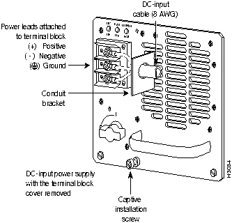
Follow these steps to replace a DC-input power supply. Use only copper conductors to connect the DC-input terminals.
Figure 23 : Removing and Replacing the DC-Input Power Cable
This completes the DC-input power supply replacement procedure. Proceed to the section "Replacing the Card Cage Assembly."
Replacing AC-Input Power Supplies
The chassis requires a minimum of 20-amp service, with a 20-amp receptacle at the power source. The power cable supplied with the chassis uses a 20-amp male plug. Figure 24 shows the cable connector plug and the 20-amp receptacle required to connect the 20-amp cable to your AC source.
Figure 24 : 20-Amp AC Power Cable Connector and Plug, and 20-Amp Receptacle
Follow these steps to replace an AC-input power supply:
This completes the AC-input power supply replacement procedure.
Proceed to the section "Replacing the Card Cage Assembly."
To complete the installation you must perform a final check of all connections, and then restart the system. This procedure is not for new systems; perform this procedure only if you have already connected the network interfaces and performed the first-time startup procedures in the Cisco 7513 Hardware Installation and Maintenance publication.
Follow these steps to restart the system and verify that the system restarts successfully:
If the power supplies do not start up, or if the system or any interfaces do not initialize properly, refer to the Cisco 7513 Hardware Installation and Maintenance publication for additional information and installation troubleshooting procedures. If necessary, contact a service representative. (See the following section "Cisco Information Online.")
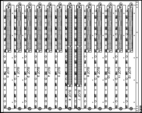
Figure 25 : Slot Numbering (Use with Table 2)
Table 2 : Port and Slot Configuration Worksheet (Refer to Figure 25)
This section repeats in multiple languages the warnings in this guide.
Following are translations for the warning statements used in this text.
DC Power Disconnection Warning
Waarschuwing Deze waarschuwing geldt slechts voor toestellen die voorzien zijn van voedingen met gelijkstroom ingang. Voordat u een van de onderstaande procedures uitvoert, dient u te controleren of de stroom naar het gelijkstroom circuit uitgeschakeld is. Om u ervan te verzekeren dat alle stroom UIT is geschakeld, kiest u op het schakelbord de stroomverbreker die het gelijkstroom circuit bedient, draait de stroomverbreker naar de UIT positie en plakt de schakelaarhendel van de stroomverbreker met plakband in de UIT positie vast.
Varoitus Seuraava varoitus koskee ainoastaan tasavirran syöttövirtalähteellä varustettuja laitteita. Varmista, että tasavirtapiirissä ei ole virtaa ennen seuraavien toimenpiteiden suorittamista. Varmistaaksesi, että virta on KATKAISTU täysin, paikanna tasavirrasta huolehtivassa kojetaulussa sijaitseva suojakytkin, käännä suojakytkin KATKAISTU-asentoon ja teippaa suojakytkimen varsi niin, että se pysyy KATKAISTU-asennossa.
Attention Cet avertissement ne s'applique qu'aux unités équipées d'alimentations en courant continu. Avant de pratiquer l'une quelconque des procédures ci-dessous, vérifier que le circuit en courant continu n'est plus sous tension. Pour en être sûr, localiser le disjoncteur situé sur le panneau de service du circuit en courant continu, placer le disjoncteur en position fermée (OFF) et, à l'aide d'un ruban adhésif, bloquer la poignée du disjoncteur en position OFF.
Warnung Diese Warnung gilt nur für Einheiten, die mit Gleichstrom-Netzgeräten ausgestattet sind. Vor Ausführung der folgenden Vorgänge ist sicherzustellen, daß die Gleichstromschaltung keinen Strom erhält. Um sicherzustellen, daß sämtlicher Strom abgestellt ist, machen Sie auf der Schalttafel den Unterbrecher für die Gleichstromschaltung ausfindig, stellen Sie den Unterbrecher auf AUS, und kleben Sie den Schaltergriff des Unterbrechers mit Klebeband in der AUS-Stellung fest-
Avvertenza Questa avvertenza riguarda solo le unità dotate di alimentatori con ingresso CC. Prima di svolgere una qualsiasi delle procedure seguenti, verificare che il circuito CC non sia alimentato. Per verificare che tutta l'alimentazione sia scollegata (OFF), individuare l'interruttore automatico sul quadro strumenti che alimenta il circuito CC, mettere l'interruttore in posizione OFF e fissarlo con nastro adesivo in tale posizione.
Advarsel Denne advarselen gjelder kun for enheter som er utstyrt med strømforsyningsenheter for likestrøm. Før noen av disse prosedyrene utføres, kontroller at strømmen er frakoblet likestrømkretsen. Sørg for at all strøm er slått AV. Dette gjøres ved å lokalisere strømbryteren på brytertavlen som betjener likestrømkretsen, slå strømbryteren til AV-stilling og teipe bryterhåndtaket på strømbryteren i AV-stilling.
Aviso Este aviso aplica-se apenas a sistemas equipados com unidades de entrada de fornecimento de corrente contínua. Antes de executar um dos seguintes procedimentos, certifique-se que desligou a fonte de alimentação de energia do circuito de corrente contínua. Para se assegurar que toda a corrente foi DESLIGADA, localize o disjuntor no painel que serve o circuito de corrente contínua e coloque-o na posição OFF (Desligado), segurando nessa posição a manivela do interruptor do disjuntor com fita isoladora.
¡Atención! Esta advertencia únicamente se aplica si el equipo posee fuente de alimentación con entrada de corriente continua (CC). Antes de proceder con los siguientes pasos, comprobar que la alimentación del circuito de corriente continua (CC) esté cortada (OFF). Para asegurarse de que toda la alimentación esté cortada (OFF), localizar el interruptor automático en el panel que alimenta al circuito de corriente continua, cambiar el interruptor automático a la posición de Apagado (OFF), y sujetar con cinta la palanca del interruptor automático en posición de Apagado (OFF).
Varning! Denna varning berör endast enheter utrustade med strömförsörjningsenheter för inmatad likström. Innan du utför någon av följande procedurer måste du kontrollera att strömförsörjningen till likströmskretsen är bruten. Kontrollera att all strömförsörjning är BRUTEN genom att slå AV det överspänningsskydd som skyddar likströmskretsen och tejpa fast överspänningsskyddets omkopplare i FRÅN-läget.
Waarschuwing Dit toestel kan meer dan één netsnoer hebben. Om het risico van een elektrische schok te verminderen, dient u de stekkers van de twee netsnoeren uit het stopcontact te halen voordat u het toestel een servicebeurt geeft.
Varoitus Tässä laitteessa saattaa olla useampi kuin yksi virtajohto. Irrota molemmat virtalähteestä tulevat johtimet ennen laitteen huoltamista, jotta vältät sähköiskun vaaran.
Attention Il est possible que cette unité soit munie de plusieurs cordons d'alimentation. Pour éviter les risques d'électrocution, débrancher les deux cordons d'alimentation avant de réparer l'unité.
Warnung Diese Einheit hat möglicherweise mehr als ein Netzkabel. Zur Verringerung der Stromschlaggefahr trennen Sie beide Netzgerätekabel ab, bevor Sie die Einheit warten.
Avvertenza Questa unità potrebbe essere dotata di più di un cavo di alimentazione. Per ridurre il rischio di scossa elettrica, scollegare i due cavi di alimentazione prima di procedere alla manutenzione dell'unità.
Advarsel Denne enheten kan være utstyrt med mer enn én strømledning. Koble fra de to strømledningene før det utføres reparasjonsarbeid på enheten for å redusere faren for elektriske støt.
Aviso Esta unidade poderá ter mais do que um cabo de alimentação. Para reduzir o risco de choque eléctrico, desligue os dois cabos de alimentação antes de efectuar reparações na unidade.
¡Atención! Puede ser que este equipo posea más de un cable de alimentación. Para reducir el riesgo de descarga eléctrica, desenchufar los dos cables antes de proceder al mantenimiento de la unidad.
Varning! Denna enhet kan vara försedd med mer än en nätsladd. För att minska risken för elektriska stötar skall båda nätsladdarna dras ur innan du utför underhållsarbete på enheten.
DC Power Supply Wiring Warning
Waarschuwing Deze waarschuwing geldt slechts voor toestellen die voorzien zijn van voedingen met gelijkstroom ingang. Figuur 1-4 toont de Cisco 7513 aansluitstrip van de gelijkstroom voeding. Breng de bedrading aan voor de gelijkstroom voeding met behulp van de juiste aansluitpunten aan het draadeinde, zoals te zien is in Figuur 1-4. De juiste bedradingsvolgorde is aarde naar aarde, positief naar positief (lijn naar L) en negatief naar negatief (neutraal naar N). Let op dat de aarddraad altijd het eerst verbonden en het laatst ontkoppeld wordt.
Varoitus Seuraava varoitus koskee ainoastaan tasavirran syöttövirtalähteellä varustettuja laitteita. Kuva 1-4 esittää Cisco 7513 -tasavirran pääterasiaa. Liitä tasavirtalähde johdon avulla käyttäen sopivia kiinnityskorvia johdon päässä kuvan 1-4 esittämällä tavalla. Oikea kytkentäjärjestys on maajohto maajohtoon, positiivinen positiiviseen (johto L:ään) ja negatiivinen negatiiviseen (nollajohto N:ään). Ota huomioon, että maajohto on aina yhdistettävä ensin ja irrotettava viimeisenä.
Attention Cet avertissement ne s'applique qu'aux unités équipées d'alimentations en courant continu. La figure 1-4 illustre le bloc de connexion de l'alimentation en courant continu du Cisco 7513. Câbler l'alimentation en courant continu en fixant les cosses qui conviennent aux extrémités câblées conformément à la figure 1-4. La séquence de câblage à suivre est terre-terre, positif-positif (ligne sur L), et négatif-négatif (neutre sur N). Noter que le fil de masse doit toujours être connecté en premier et déconnecté en dernier.
Warnung Diese Warnung gilt nur für Einheiten, die mit Gleichstrom-Netzgeräten ausgestattet sind. Auf Abb. 1-4 ist der Terminalblock des Gleichstrom-Netzgeräts von Cisco 7513 abgebildet. Verdrahten Sie das Gleichstrom-Netzgerät unter Verwendung von geeigneten Kabelschuhen am Verdrahtungsende (siehe Abb. 1-4). Die richtige Verdrahtungsfolge ist Erde an Erde, positiv an positiv (Leitung an L) und negativ an negativ (neutral an N). Beachten Sie bitte, daß der Erdungsdraht immer als erstes verbunden und als letztes abgetrennt werden sollte.
Avvertenza Questa avvertenza riguarda solo le unità dotate di alimentatori con ingresso CC. La Figura 1-4 mostra la morsettiera dell'alimentatore CC 7513 Cisco. Cablare l'alimentatore CC usando i connettori adatti all'estremità del cablaggio, come illustrato nella Figura 1-4. La corretta sequenza di cablaggio è da massa a massa, da positivo a positivo (da linea ad L) e da negativo a negativo (da neutro a N). Tenere presente che il filo di massa deve sempre venire collegato per primo e scollegato per ultimo.
Advarsel Denne advarselen gjelder kun for enheter som er utstyrt med strømforsyningsenheter for likestrøm. Figur 1-4 viser Cisco 7513 kabelhode for likestrømsforsyningsenheter. Koble likestrømsforsyningsenheten ved hjelp av passende kabelsko i enden av ledningen, slik som vist i figur 1-4. Riktig ledningskobling er jord til jord, positiv til positiv (linje til L), og negativ til negativ (nøytral til ~). Legg merke til at jordledningen alltid bør tilkobles først og frakobles sist.
Aviso Este aviso refere-se apenas a sistemas equipados com unidades de entrada de fornecimento de corrente contínua. A Figura 1-4, mostra o bloco do terminal Cisco 7513 de fornecimento de corrente contínua. Instale o fornecimento de corrente contínua, usando os terminais apropriados das terminações de cabo, conforme indicado na Figura 1-4. A sequência correcta de instalação é terra-a-terra, positivo-positivo (linha para L) e negativo-negativo (neutro para N). Note que o fio de terra deverá ser sempre o primeiro a ser ligado, e o último a ser desligado.
¡Atención! Esta advertencia únicamente se aplica si el equipo posee fuentes de alimentación con entrada de corriente continua (CC). La figura <x.yy> muestra la caja de bornes de la fuente de alimentación de corriente continua del equipo Cisco 7513. Cablear la fuente de alimentación de corriente continua utilizando las lengüetas de conexión apropiadas para el extremo del hilo, tal y como se demuestra en la figura <x.yy>. Las conexiones en el cableado deben realizarse en el siguiente orden: tierra con tierra, positivo con positivo (la línea con la L) y negativo con negativo (el neutro con la N). OJO: el hilo de tierra debe siempre conectarse el primero y desconectarse el último.
Varning!! Denna varning berör endast enheter utrustade med strömförsörjningsenheter för inmatad likström. Figur 1-4 visar Cisco 7513 anslutningsplint för strömförsörjningsenhet för likström. Koppla ledningarna till strömförsörjningsenheten för likström med lämpliga kabelskor i ledningsändarna såsom visas i Figur 1-4. Korrekt kopplingssekvens är jord till jord, positiv till positiv (linje till L) och negativ till negativ (neutral till N). Observera att jordledningen alltid skall anslutas först och kopplas bort sist.
Waarschuwing Deze waarschuwing geldt slechts voor toestellen die voorzien zijn van voedingen met gelijkstroom ingang. Nadat de bedrading van de gelijkstroom voeding aangebracht is, verwijdert u het plakband van de schakelaarhendel van de stroomverbreker en schakelt de stroom weer in door de hendel van de stroomverbreker naar de AAN positie te draaien.
Varoitus Seuraava varoitus koskee ainoastaan tasavirran syöttövirtalähteellä varustettuja laitteita. Yhdistettyäsi tasavirtalähteen johdon avulla poista teippi suojakytkimen varresta ja kytke virta uudestaan kääntämällä suojakytkimen varsi KYTKETTY-asentoon.
Attention Cet avertissement ne s'applique qu'aux unités équipées d'alimentations en courant continu. Une fois l'alimentation connectée, retirer le ruban adhésif servant à bloquer la poignée du disjoncteur et rétablir l'alimentation en plaçant cette poignée en position de marche (ON).
Warnung Diese Warnung gilt nur für Einheiten, die mit Gleichstrom-Netzgeräten ausgestattet sind. Nach Verdrahtung des Gleichstrom-Netzgeräts entfernen Sie das Klebeband vom Schaltergriff des Unterbrechers und schalten den Strom erneut ein, indem Sie den Griff des Unterbrechers auf EIN stellen.
Avvertenza Questa avvertenza riguarda solo le unità dotate di alimentatori con ingresso CC. Dopo aver eseguito il cablaggio dell'alimentatore CC, togliere il nastro adesivo dall'interruttore automatico e ristabilire l'alimentazione spostando all'interruttore automatico in posizione ON.
Advarsel Denne advarselen gjelder kun for enheter som er utstyrt med strømforsyningsenheter for likestrøm. Etter at likestrømsenheten er tilkoblet, fjernes teipen fra håndtaket på strømbryteren, og deretter aktiveres strømmen ved å flytte håndtaket på strømbryteren til PÅ-stilling.
Aviso Este aviso aplica-se apenas a sistemas equipados com unidades de entrada de fornecimento de corrente contínua. Depois de ligar o sistema de fornecimento de corrente contínua, retire a fita isoladora da manivela do disjuntor, e volte a ligar a corrente ao deslocar a manivela para a posição ON (Ligado).
¡Atención! Esta advertencia únicamente se aplica si el equipo posee fuente de alimentación con entrada de corriente continua (CC). Después de cablear la fuente de alimentación de corriente continua, retirar la cinta de la palanca del interruptor automático, y restablecer la alimentación cambiando la palanca a la posición de Encendido (ON).
Varning! Denna varning berör endast enheter utrustade med strömförsörjningsenheter för inmatad likström. När du har kopplat ledningarna till strömförsörjningsenheten för inmatad likström tar du bort tejpen från överspänningsskyddets omkopplare och slår på strömmen igen genom att ställa överspänningsskyddets omkopplare i TILL-läget.
Waarschuwing Deze waarschuwing geldt slechts voor toestellen die voorzien zijn van voedingen met gelijkstroom ingang. Wanneer geslagen bedrading vereist is, dient u bedrading te gebruiken die voorzien is van goedgekeurde aansluitingspunten, zoals het gesloten-lus type of het grijperschop type waarbij de aansluitpunten omhoog wijzen. Deze aansluitpunten dienen de juiste maat voor de draden te hebben en dienen zowel de isolatie als de geleider vast te klemmen.
Varoitus Seuraava varoitus koskee ainoastaan tasavirran syöttövirtalähteellä varustettuja laitteita. Jos säikeellinen johdin on tarpeen, käytä hyväksyttyä johdinliitäntää, esimerkiksi suljettua silmukkaa tai kourumaista liitäntää, jossa on ylöspäin käännetyt kiinnityskorvat. Tällaisten liitäntöjen tulee olla kooltaan johtimiin sopivia ja niiden tulee puristaa yhteen sekä eristeen että johdinosan.
Attention Cet avertissement ne s'applique qu'aux unités équipées d'alimentations en courant continu. Quand des fils torsadés sont nécessaires, utiliser des douilles terminales homologuées telles que celles à circuit fermé ou du type àplage ouverte avec cosses rebroussées. Ces douilles terminales doivent être de la taille qui convient aux fils et doivent être refermées sur la gaine isolante et sur le conducteur.
Warnung Diese Warnung gilt nur für Einheiten, die mit Gleichstrom-Netzgeräten ausgestattet sind. Wenn Litzenverdrahtung erforderlich ist, sind zugelassene Verdrahtungsabschlüsse, z.B. für einen geschlossenen Regelkreis oder gabelförmig, mit nach oben gerichteten Kabelschuhen zu verwenden. Diese Abschlüsse sollten die angemessene Größe für die Drähte haben und sowohl die Isolierung als auch den Leiter festklemmen.
Avvertenza Questa avvertenza riguarda solo le unità dotate di alimentatori con ingresso CC. Quando occorre usare trecce, usare connettori omologati, come quelli a occhiello o a forcella con linguette rivolte verso l'alto. I connettori devono avere la misura adatta per il cablaggio e devono serrare sia l'isolante che il conduttore.
Advarsel Denne advarselen gjelder kun for enheter som er utstyrt med strømforsyningsenheter for likestrøm. Hvis det er nødvendig med flertrådede ledninger, brukes godkjente ledningsavslutninger, som for eksempel lukket sløyfe eller spadetype med oppoverbøyde kabelsko. Disse avslutningene skal ha riktig størrelse i forhold til ledningene, og skal klemme sammen både isolasjonen og lederen.
Aviso Este aviso aplica-se apenas a sistemas equipados com unidades de entrada de fornecimento de corrente contínua. Quando forem requeridas montagens de instalação eléctrica de cabo torcido, use terminações de cabo aprovadas, tais como, terminações de cabo em circuito fechado e planas com terminais de orelha voltados para cima. Estas terminações de cabo deverão ser do tamanho apropriado para os respectivos cabos, e deverão prender simultaneamente o isolamento e o fio condutor.
¡Atención! Esta advertencia únicamente se aplica si el equipo posee fuentes de alimentación con entrada de corriente continua (CC). Cuando se necesite hilo trenzado, utilizar terminales para cables homologados, tales como las de tipo "bucle cerrado" o "espada", con las lengüetas de conexión vueltas hacia arriba. Estos terminales deberán ser del tamaño apropiado para los cables que se utilicen, y tendrán que sujetar tanto el aislante como el conductor.
Varning! Denna varning berör endast enheter utrustade med strömförsörjningsenheter för inmatad likström. När flertrådiga ledningar krävs måste godkända ledningskontakter användas, t.ex. kabelsko av sluten eller öppen typ med uppåtvänd tapp. Storleken på dessa kontakter måste vara avpassad till ledningarna och måste kunna hålla både isoleringen och ledaren fastklämda.
Cisco Information Online (CIO) is Cisco Systems' primary, real-time support channel. Maintenance customers and partners can self-register on CIO to obtain additional content and services.
Available 24 hours a day, 7 days a week, CIO provides a wealth of standard and value-added services to Cisco's customers and business partners. CIO services include product information, software updates, release notes, technical tips, the Bug Navigator, configuration notes, brochures, descriptions of service offerings, and download access to public and authorized files.
CIO serves a wide variety of users through two interfaces that are updated and enhanced simultaneously---a character-based version and a multimedia version that resides on the World Wide Web (WWW). The character-based CIO (called "CIO Classic") supports Zmodem, Kermit, Xmodem, FTP, Internet e-mail, and fax download options, and is excellent for quick access to information over lower bandwidths. The WWW version of CIO provides richly formatted documents with photographs, figures, graphics, and video, as well as hyperlinks to related information.
You can access CIO in the following ways:
For a copy of CIO's Frequently Asked Questions (FAQ), contact Obtaining Additional Information
To order UniverCD, Cisco's online library of product information on CD-ROM, or printed publications, refer to "Ordering Cisco Documentation," which is in your chassis warranty pack.
If you are a network administrator and need personal technical assistance with a Cisco product that is under warranty or covered by a maintenance contract, contact Cisco's Technical Assistance Center (TAC) at 800 553-2447, 408 526-7209, or
Copyright 1988-1996 © Cisco Systems Inc.
![]()
![]()
![]()
![]()
![]()
![]()
If you install the chassis from the front of the rack (with the interface processor end of the chassis toward the front of the rack), you do not need to remove the power strips from the rack; however, this orientation might place the chassis opposite from most of the other equipment in the rack.
![]()
![]()
![]()
If you are installing a new chassis or, if you have already disconnected all power and interface cables and removed all power supplies, processor modules, and the card cage assembly, proceed to the section "Moving the Chassis into the Rack" on page 31.
![]()
![]()
![]()
![]()
![]()
![]()
![]()
![]()
![]()
![]()
![]()
![]()
![]()
![]()
![]()
![]()

(display text omitted)
GS Software (RSP-K), Version 10.3(571)
Copyright (c) 1986-1995 by cisco Systems, Inc.
Compiled Wed 10-May-95 25:12
RSP2 (Risc 4600) processor with 16384K bytes of memory.
(display text omitted)
1 EIP controller (2 Ethernet).
8192K bytes of flash memory on embedded flash (in RSP2).
Port
Slot 0
Slot 1
Slot 2
Slot 3
Slot 4
Slot 51
Slot 8
Slot 9
Slot 10
Slot 11
Slot 12
1
2
3
4
5
6
7
8
Router Name
Location
Serial Number
1 Slots 6 and 7 are reserved for the RSP2.
![]()
![]()
![]()
![]()
![]()
http://www.cisco.com
cio.cisco.com
ciohelp@cisco.com.
For additional information, contact
cioteam@cisco.com.
tac@cisco.com.
To obtain general information about Cisco Systems, Cisco products, documentation, UniverCD, or upgrades, contact 800 553-6387, 408 526-7208, or
csrep@cisco.com.

![]()
![]()
![]()
![]()
![]()
![]()
![]()
![]()