|
|

Asynchronous Transfer Mode Interface Processor (AIP) Installation and Configuration
Product Numbers: CX-AIP-TM=, CX-AIP-SM=, CX-AIP-SS=, CX-AIP-E3=, CX-AIP-DS3=, CLIP-E3-EMI=, and CAB-ATM-DS3/E3=
This publication contains instructions for installing the Asynchronous Transfer Mode (ATM) Interface Processor (AIP). This publication also contains basic configuration steps and examples.
Sections in this publication include the following:
For complete descriptions of interface subcommands and the configuration options available for ATM interfaces, refer to the Router Products Configuration Guide and Router Products Command Summary publications.
The following are common ATM terms and acronyms for your reference:
AAL---ATM Adaptation Layer. An AAL defines the conversion of user information into cells. AAL1 and AAL2 handle isochronous traffic, such as voice and video; AAL3/4 and AAL5 pertain to data communications through the segmentation and reassembly of packets.
ATM---Asynchronous transfer mode. A cell-switching and multiplexing technology combining the benefits of circuit switching (constant transmission delay, guaranteed capacity) with those of packet switching (flexibility, efficiency for intermittent traffic). ATM is defined by ITU-T standards.
Average-rate---The average rate, in Kbps, at which a given virtual circuit (VC) will transmit.
BISDN---Broadband Integrated Services Digital Network. A set of standards under development by the ITU-T for services based on ATM switching and SONET/SDH transmission.
CCITT---Consultative Committee for International Telegraph and Telephone (Although commonly referred to as the CCITT, this international standards body recently adopted the name International Telecommunication Union/Telecommunication Standardization Sector (ITU-T).
CLP---Cell loss priority.
DXI---Data exchange interface.
ILMI---Interim Local Management Interface---Described in the ATM Forum's UNI specification, ILMI allows end users to retrieve a basic set of information, such as status and configuration about virtual connections and addresses, for a particular UNI.
ITU-T---International Telecommunications Union Telecommunication Sector (formerly the Consultative Committee for International Telegraph and Telephone (CCITT))
MIB---Management Information Base.
MIC---Media Interface Connector.
MID---Message identifier---In AAL3/4 encapsulation, the 2-byte MID field allows multiplexing of streams of cells on one virtual channel.
NSAP---Network Service Access Point.
OAM---Operation and Maintenance (cells).
PDU---Protocol data unit---An OSI term for a packet.
Peak-rate---The maximum rate, in Kbps, at which VC can transmit.
PMD---Physical medium dependent. The lower half of BISDN Layer 1.
PLIM---Physical layer interface module. The PLIM contains the interface to the ATM cable. (See AIP Interface Types, page 13 .)
PVC---Permanent virtual circuit.
QOS---Quality of service.
Rate queues---Rate queues define the speed at which the individual VCs will transmit data to the remote end. Every VC must be associated with one rate queue. After attachment to this rate queue, the VC is assumed to have its peak rate set to that of the rate queue. Each rate queue can be configured independently to a portion of the overall bandwidth available on the ATM link. The combined bandwidths of all rate queues should not exceed the total bandwidth available. For E3, rate queues >34 are disallowed. For DS3, rate queues >45 are disallowed.
SAR---Segmentation and reassembly.
SDH---Synchronous Digital Hierarchy. International standard for optical digital transmission at hierarchical rates from 155 Mbps to 2.5 Gbps and greater.
SDU---Service data unit.
SONET---Synchronous Optical Network. An ATM UNI specification and American National Standards Institute (ANSI) standard (T1.1051988) for optical digital transmission at hierarchical rates from 51.840 Mbps (STS-N) to 2.5 Gbps and greater.
SONET OC3---Optical Carrier-3 specification.
SSCOP---Service Specific Connection Oriented Protocol---Resides in the service specific convergence sublayer of the ATM adaptation layer. SSCOP is used to transfer variable-length service data units between users of SSCOP. SSCOP provides for the recovery of lost or corrupted SDUs.
SSCS---Service specific convergence sublayer.
SVC---Switched virtual circuit.
TAXI---Transparent Asynchronous Transmitter/Receiver Interface
UNI---User-to-Network Interface. An ATM interface defined by the ATM Forum for public and private ATM network access.
VC---Virtual circuit---Point-to-point connections to remote hosts/routers. Each ATM VC has the following characteristics associated with the VC: peak rate, average rate, cell quota, quality of service (QOS), AAL mode (AAL3/4 or AAL5), encapsulation type (LLC/SNAP, NLPID, SMDS, MUX, QSAAL). The VC characteristics are defined when the VC is created.
VCD---Virtual circuit descriptor.
VPI/VCI---Virtual path identifier/virtual channel identifier. ATM virtual connection information. A virtual path is a generic term for a bundle of virtual channels that have the same end point.
Asynchronous Transfer Mode Overview
Asynchronous Transfer Mode (ATM) uses cell-switching and multiplexing technology which combines the benefits of circuit switching (constant transmission delay and guaranteed capacity) with those of packet switching (flexibility and efficiency for intermittent traffic).
ATM is a connection-oriented environment. All traffic to or from an ATM network is prefaced with a virtual path identifier (VPI) and virtual channel identifier (VCI). A VPI/VCI pair is considered a single virtual circuit (VC). Each VC is a private connection to another node on the ATM network. Each VC is treated as a point-to-point mechanism to another router or host and is capable of supporting bidirectional traffic.
Each ATM node is required to establish a separate connection to every other node in the ATM network that it must communicate with. All such connections are established using a PVC or an SVC with an ATM signaling mechanism. This signaling is based on the ATM Forum UNI Specification V3.0.
Each VC is considered a complete and separate link to a destination node. Users can encapsulate data as they see fit across the connection. The ATM network disregards the contents of the data. The only requirement is that data be sent to the AIP card in the specific ATM adaptation layer (AAL) format.
An AAL defines the conversion of user information into cells. The AAL segments upper-layer information into cells at the transmitter and reassembles them at the receiver. AAL3/4 and AAL5 support data communications. AAL3/4 is supported as of Cisco Internetwork Operating System (Cisco IOS) Release 10.2 and later.
An ATM connection transfers raw bits of information to a destination router/host. The ATM router takes the common part convergence sublayer (CPCS) frame, carves it up into 53-byte cells, and sends these cells to the destination router or host for reassembly. Forty-eight bytes of each cell are used for the CPCS data; the remaining 5 bytes are used for cell routing. The 5-byte cell header contains the destination VPI/VCI, payload type, cell loss priority (CLP), and header error control.
Unlike a LAN, which is connectionless, ATM requires certain features to provide a LAN environment to the users. One such feature is broadcast capability. Protocols wishing to broadcast packets to all stations in a subnet must be allowed to do so with a single call to Layer 2. In order to support broadcasting, the router allows the user to specify a particular VC as a broadcast VC. When the protocol passes a packet with a broadcast address to the ATM driver, the packet is duplicated and sent to each VC marked as a broadcast VC. This method is known as pseudobroadcasting.
This section provides a brief description of Cisco 7000 series routers and the ATM interface processor (AIP).
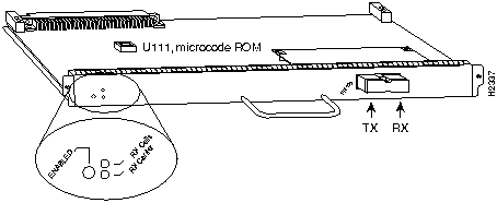
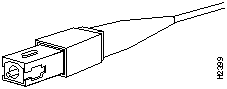
The AIP (see Figure 1) provides a single ATM network interface for Cisco 7000 series routers. An overview of the Cisco 7000 series and a description of the AIP follow.
Figure 1 : ATM Interface Processor (AIP) with 100 Mbps UNI PLIM
The ATM network interface for a Cisco 7000 series router resides on a modular interface processor, the AIP, which provides a direct connection between the high-speed Cisco Extended Bus (CxBus) and the external networks. The physical layer interface module (PLIM) on the AIP determines the type of ATM connection. There are no restrictions on slot locations or sequence; you can install an AIP in any available interface processor slot.
The AIP supports the following features:
To ensure correct operation of the E3, DS3, and TAXI AIPs, Hardware Revision 1.3 (shipped from March 1995), the following minimum Cisco IOS release levels are required: 10.0(9), 10.2(5), 10.3(1), or later.
ATM Management Information Base (MIB)
The ATM UNI specification defines the required MIB functionality for ATM interfaces. MIB attributes are readable and writable across the Interim Local Management Interface (ILMI) using a Simple Network Management Protocol (SNMP). The ILMI uses SNMP, without UDP, and Internet Protocol (IP) addressing along with the ATM MIB.
The AIP supports RFC 1213 interface MIBs as specified in the ATM MIB V2 specification. Refer to the ATM UNI specification for additional details of the MIB. DS3 MIB variables are outlined in RFC 1407.
What is the Cisco 7000 Family?
The Cisco 7000 family of routers consists of the Cisco 7000 series routers: Cisco 7000 and Cisco 7010; and the Cisco 7500 series: Cisco 7505, Cisco 7507, and Cisco 7513. The following sections describe the Cisco 7000 series nd Cisco 7500 series.
What is the Cisco 7000 Series?
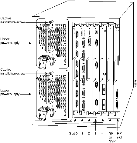
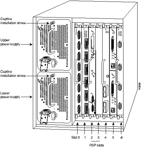
The Cisco 7000 series comprises the seven-slot Cisco 7000 (see Figure 2) and the five-slot Cisco 7010 (see Figure 3). Both models use the same Route Processor (RP), Switch Processor (SP) or Silicon Switch Processor (SSP), CxBus interface processors, and arbiter (MAS-7KARB). The Cisco 7000 provides five interface slots and offers a second modular power supply for redundant power. The Cisco 7010 provides three interface slots, which each offer the same performance as the Cisco 7000.
Figure 2 shows the interface processor end of the Cisco 7000 model, which provides access to the seven processor slots and the removable power supplies. When facing the interface processor end of the chassis, the RP and SP slot are on the far right. The five interface processor slots are numbered 0 to 4 from left to right.
In both models, interface processor slots support any combination of network interface types: ATM, Ethernet, Token Ring, fiber distributed data interface (FDDI), serial, and high-speed serial interface (HSSI). The RP, SP, and interface processors are keyed with guides on the backplane to prevent them from being fully inserted in the wrong slot.
Figure 2 : Cisco 7000, Interface Processor End
Figure 3 shows the interface processor end of the Cisco 7010 model, which provides access to the five processor slots, the AC power input receptacle, the power switch, and a power status indicator. When facing the interface processor end of the chassis, the RP and SP slots are at the top. The three interface processor slots are numbered from the bottom up beginning with slot 0 (the bottom slot) through 2 (the center slot).
Figure 3 : Cisco 7010, Interface Processor End
What is the Cisco 7500 Series?
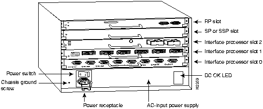
The Cisco 7500 series consists of three router models: the Cisco 7505, the Cisco 7507, and the Cisco 7513. All three models provide high reliability, availability, serviceability, and performance. The three systems support multiprotocol, multimedia routing, and bridging with a wide variety of protocols and any combination of Ethernet, Fast Ethernet, Token Ring, Fiber Distributed Data Interface (FDDI), serial, multichannel, channel attachment, and High-Speed Serial Interface (HSSI) media. Network interfaces reside on modular interface processors, which provide a direct connection between the high-speed, 1.067-gigabits-per-second (Gbps) Cisco Extended Bus (CyBus) and the external networks.
Figure 4 shows the rear of the five-slot Cisco 7505 router. In the Cisco 7505, one slot (4) is reserved for the Route Switch Processor (RSP1), which contains the system processor and performs packet switching functions. Slots 0 through 3 are for interface processors.
Figure 4 : Cisco 7505, Interface Processor End
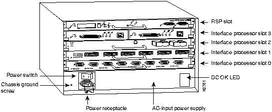
Figure 5 shows the rear of the seven-slot Cisco 7507 router. In the Cisco 7507, up to two slots (2 and 3) are reserved for the Route Switch Processor (RSP2), which contains the system processor and performs packet switching functions. Slots 0 and 1 and 4 through 6 are for interface processors.
Figure 5 : Cisco 7507, Interface Processor End
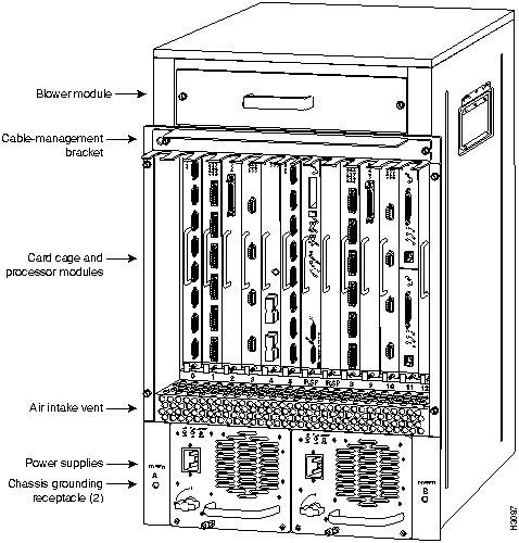
Figure 6 shows the rear of the Cisco 7513, with two AC-input power supplies installed. Two slots (6 and 7) are reserved for the second generation Route Switch Processor (RSP2), which contains the system processor and performs packet switching functions. Slots 0 through 5 and 8 through 12 are for interface processors.
Figure 6 : Cisco 7513, Interface Processor End
Installing and Removing Processor Modules
The processor modules slide into slots in the rear of the chassis and connect directly to the backplane. The backplane slots are keyed so that the processor modules can be installed only in the slots designated for them.
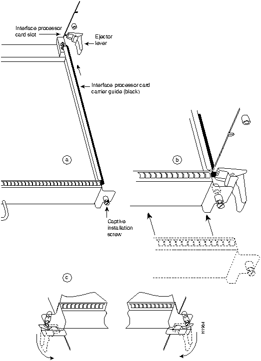
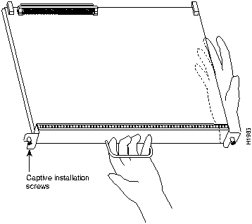
Figure 7 shows the ejector levers and captive installation screws on a typical interface processor. To remove an interface processor, loosen the captive screws and pull the ejector levers to the sides; then pull the module out using the handle. To insert an interface processor, reverse the process, making sure to firmly seat the interface processor in its connectors on the backplane. For detailed directions, follow the procedures in "Removing the AIP" and "Installing the AIP."
The captive installation screws on the ends (see Figure 7) of each faceplate, when tightened, provide EMI shielding and also help ensure proper seating in the backplane. After using the ejector levers to install an AIP, tighten the captive installation screws to prevent the AIP from becoming partially dislodged from the backplane. These screws must be tightened to meet EMI specifications.
Figure 7 : Ejector Levers and Captive Installation Screws
All AIP ATM interfaces are full-duplex. You must use the appropriate ATM interface cable to connect the AIP with an external ATM network. Refer to the section "ATM Interface Cables" on page 17 for descriptions of ATM connectors. The AIP, shown in Figure 1, provides an interface to ATM switching fabrics for transmitting and receiving data at rates of up to 155 Mbps bidirectionally; the actual rate is determined by the PLIM. The AIP can support PLIMs that connect to the following physical layers:
For wide-area networking, ATM is currently being standardized for use in Broadband Integrated Services Digital Networks (BISDNs) by the International Telecommunications Union Telecommunication Standardization Sector (ITU-T) (formerly the Consultative Committee for International Telegraph and Telephone (CCITT)) and the American National Standards Institute (ANSI). BISDN supports rates from E3 (34 Mbps) to multiple gigabits per second (Gbps). The DS3 interface performs physical layer translation from the AIP to a DS3 line interface in accordance with ATM Forum UNI Specification Version 3.1, ACCUNET T45 service specifications, and ANSI T1.107.
The SONET specification for fiber-optic transmission defines two types of fiber: single mode and multimode. Modes can be thought of as bundles of light rays entering the fiber at a particular angle. Single-mode fiber allows only one mode of light to propagate through the fiber, while multimode fiber allows multiple modes of light to propagate through the fiber. Because multiple modes of light propagating through the fiber travel different distances depending on the entry angles, causing them to arrive at the destination at different times (a phenomenon called modal dispersion), singlemode fiber is capable of higher bandwidth and greater cable run distances than multimode fiber.
The typical maximum distances for single-mode and multimode transmissions, as defined by SONET, are in Table 1. If the distance between two connected stations is greater than these maximum distances, significant signal loss can result, making transmission unreliable.
Table 1 : SONET Maximum Fiber-Optic Transmission Distances
To design an efficient optical data link, evaluate the power budget. The power budget is the amount of light available to overcome attenuation in the optical link and to exceed the minimum power that the receiver requires to operate within its specifications. Proper operation of an optical data link depends on modulated light reaching the receiver with enough power to be correctly demodulated.
Attenuation, caused by the passive media components (cables, cable splices, and connectors), is common to both multimode and single-mode transmission.
The following variables reduce the power of the signal (light) transmitted to the receiver in multimode transmission:
Attenuation is significantly lower for optical fiber than for other media. For multimode transmission, chromatic and modal dispersion reduce the available power of the system by the combined dispersion penalty (dB). The power lost over the data link is the sum of the component, dispersion, and modal losses.
Table 2 lists the factors of attenuation and dispersion limit for typical fiber-optic cable.
Table 2 : Typical Fiber-Optic Link Attenuation and Dispersion Limits
Approximating the AIP Power Margin
The LED used for a multimode transmission light source creates multiple propagation paths of light, each with a different path length and time requirement to cross the optical fiber, causing signal dispersion (smear). Higher order mode loss (HOL) results from light from the LED entering the fiber and being radiated into the fiber cladding. A worst case estimate of power margin (PM) for multimode transmissions assumes minimum transmitter power (PT), maximum link loss (LL), and minimum receiver sensitivity (PR). The worst case analysis provides a margin of error, although not all of the parts of an actual system will operate at the worst case levels.
The power budget (PB) is the maximum possible amount of power transmitted. The following equation lists the calculation of the power budget:
The power margin calculation is derived from the power budget and subtracts the link loss, as follows:
If the power margin is positive, as a rule, the link will work.
Table 3 lists the factors that contribute to link loss and the estimate of the link loss value attributable to those factors.
Table 3 : Estimating Link Loss
After calculating the power budget minus the data link loss, the result should be greater than zero. Results less than zero may have insufficient power to operate the receiver.
For SONET versions of the AIP module, the signal must meet the worst case parameters listed in Table 4.
Table 4 : AIP SONET Signal Requirements
Multimode Power Budget Example with Sufficient Power for Transmission
The following is an example multimode power budget calculated based on the following variables:
Estimate the power budget as follows:
The value of 2.5 dB indicates that this link would have sufficient power for transmission.
Multimode Power Budget Example of Dispersion Limit
Following is an example with the same parameters as the previous example, but with a multimode link distance of 4 km:
The value of 1.5 dB indicates that this link would have sufficient power for transmission. But, due to the dispersion limit on the link (4 km x 155.52 MHz > 500 MHzkm), this link would not work with multimode fiber. In this case, single-mode fiber would be the better choice.
The singlemode signal source is an injection laser diode. Single-mode transmission is useful for longer distances, because there is a single transmission path within the fiber and smear does not occur. In addition, chromatic dispersion is also reduced because laser light is essentially monochromatic.
The maximum overload specification on the single-mode receiver is --14 dBm. The single-mode receiver can be overloaded when using short lengths of fiber because the transmitter can transmit up to --8 dB, while the receiver could be overloaded at --14 dB, but no damage to the receiver will result. To prevent overloading the receiver connecting short fiber links, insert a 5 to 10 dB attenuator on the link between any singlemode SONET transmitter and the receiver.
SONET Single-Mode Power Budget Example
The following example of a single-mode power budget is of a two buildings, 11 kilometers apart, connected through a patch panel in an intervening building with a total of 12 connectors.
Estimate the power budget as follows:
The value of 2.5 dB indicates that this link would have sufficient power for transmission and is not in excess of the maximum receiver input power.
Using Statistics to Estimate the Power Budget
Statistical models more accurately determine the power budget than the worst case method. Determining the link loss with statistical methods requires accurate knowledge of variations in the data link components. Statistical power budget analysis is beyond the scope of this document. For further information, refer to UNI Forum specifications, ITU-T standards, and your equipment specifications.
The following publications contain information on determining attenuation and power budget:
The ATM interface cable is used to connect your router to an ATM network or to connect two routers back-to-back.
Cables can be obtained from the following cable vendors:
For 4B/5B traffic over multimode fiber, use the multimode MIC interface cable to connect the AIP with the external ATM switch. (See Figure 8.)
Figure 8 : Multimode Network Interface Connector (MIC Type)
For SONET/SDH multimode connections, use one multimode duplex SC connector (see Figure 9) or two single SC connectors. (See Figure 10.)
Figure 9 : Duplex SC Connector
Figure 10 : Simplex SC Connector
For SONET/SDH single-mode connections, use the single-mode (ST2) connector (bayonet-style twist-lock). (See Figure 11.)
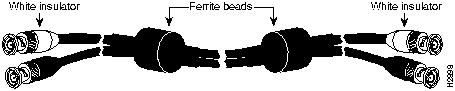
For E3 and DS3 connections, use the 75 ohm, RG-59, coaxial cable, CAB-ATM-DS3/E3, which has bayonet-style, twist-lock (BNC) connectors and ferrite beads. (See Figure 12.) The E3 and DS3 PLIMs both require cable CAB-ATM-DS3/E3.
Figure 12 : CAB-ATM-DS3/E3 Cable---RG-59 Coaxial Cable with BNC Connectors
For multimode connections, connect the multimode interface cable to the MIC connector. (See Figure 13.)
Figure 13 : MIC Connector on a TAXI 4B/5B PLIM
For multimode SONET connections, connect the multimode cable to the SC connector on the PLIM. (See Figure 14.)
Figure 14 : SONET Multimode SC Duplex PLIM
The SONET multimode SC-duplex connector is shipped with a dust plug. (See Figure 15.) Remove the plug by pulling on the plug as you squeeze the sides.
Figure 15 : SONET ATM Multimode Fiber-Optic Transceiver and Dust Plug
For single-mode SONET connections, connect the single-mode cable to the ST connector on the SONET PLIM. (See Figure 16.)
Figure 16 : SONET Single-Mode PLIM
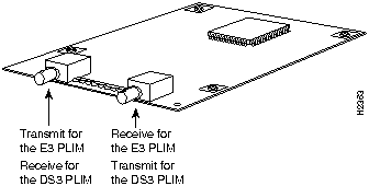
For E3 and DS3 connections, connect the coaxial cable to the BNC connector on the E3 or DS3 PLIM. (See Figure 17.)
Figure 17 : E3 and DS3 PLIM---Representative of Both PLIMs
Before you begin this installation, review the safety and ESD-prevention guidelines in this section to avoid injuring yourself or damaging the equipment. This section also provides a list of parts and tools you will need to perform the installation.
The AIP is compatible with any Cisco 7000 series router that is operating with the following system software: Cisco IOS Release 10.0 or later.
To ensure correct operation of the E3, DS3, and TAXI AIPs, Hardware Revision 1.3 (shipped from March 1995), the following minimum Cisco IOS release levels are required: 10.0(9), 10.2(5), 10.3(1), or later.
The show version command displays the current hardware configuration of the router, including the system software version that is currently loaded and running. The show controller cbus command lists all CxBus interfaces and includes the currently loaded and running microcode version for each. You can check the version of the default ROM image by either removing the board and checking the ROM labels, or by configuring the interface or system software to boot from ROM, restarting the system, and using these same commands to check the running version.
Use the show version command to display the current system software version, and use the show controller cbus command to display the microcode version of the system processor and each interface processor. In the following example of the show version command, the running system software is Release 10.0.
In the following example of the show controller cbus display, the running AIP microcode is Version 170.30. Note the display of the PLIM type (4B/5B) and available bandwidth (100 Mbps).
If the displays indicate that the running system software is an earlier version than 10.0 or that the running system processor microcode is an earlier version than 1.2, check the contents of Flash memory to determine whether the required images are available on your system. The show flash command displays a list of all files stored in Flash memory.
The following example shows that AIP Microcode Version 1.1 and SP Microcode Version 1.2 are stored in Flash memory.
If the preceding displays indicate that the required system software and microcode are not available, contact a customer service representative for upgrade information.
You need the following tools and parts to install or upgrade an AIP. If you need additional equipment, contact your service representative for ordering information.
This section lists safety guidelines to follow when working with any equipment that connects to electrical power or telephone wiring.
Follow these basic guidelines when working with any electrical equipment:
Use the following guidelines when working with any equipment that is connected to telephone wiring or to other network cabling:
Preventing Electrostatic Discharge Damage
Electrostatic discharge (ESD) damage, which can occur when electronic cards or components are improperly handled, results in complete or intermittent failures. The AIP comprises a printed circuit board that is fixed in a metal carrier. Electromagnetic interference (EMI) shielding, connectors, and a handle are integral components of the carrier. Although the metal carrier helps to protect the board from ESD, always use a preventive antistatic strap when handling the AIP. Handle the carriers by the handles and the carrier edges only; never touch the boards or connector pins.
Following are guidelines for preventing ESD damage:
The following sections describe the procedures for removing or installing an AIP in a Cisco 7000 series router. The online insertion and removal (OIR) feature allows you to install and remove an AIP without turning off system power; however, you must follow the insertion instructions carefully.
For example, failure to use the ejector levers or insert the AIP properly can cause system error messages indicating a board failure. Refer to "Online Insertion and Removal---An Overview" for a complete description of OIR.
Online Insertion and Removal---An Overview
Online insertion and removal (OIR) allows you to remove and replace CxBus interface processors while the system is operating; you do not need to notify the software or shut down the system power. This section describes the mechanical functions of the system components and stresses the importance of following the correct procedures to avoid unnecessary restarts or card failures. This section is for background information only. Subsequent sections provide specific procedures for removing and installing an AIP. All CxBus and CyBus interface processors support OIR
Each processor module contains a bus connector with which it connects to the system backplane. The bus connector is a set of tiered pins, in three lengths. The pins send specific signals to the system as they make contact with the backplane. The system assesses the signals it receives and the order in which it receives them to determine what event is occurring and what task it needs to perform, such as reinitializing new interfaces or shutting down removed ones. For example, when you insert an interface processor, the longest pins make contact with the backplane first, and the shortest pins make contact last. The system recognizes the signals and the sequence in which it receives them. The system expects to receive signals from the individual pins in this logical sequence, and the ejector levers help to ensure that the pins mate in this sequence.
When you remove or insert an interface processor, the backplane pins send signals to notify the system, which then performs as follows:
OIR functionality enables you to add, remove, or replace interface processors with the system online, which provides a method that is seamless to end users on the network, maintains all routing information, and ensures session preservation.
When you insert a new interface processor, the system runs a diagnostic test on the new interfaces and compares them to the existing configuration.
If this initial diagnostic test fails, the system remains off line for another 15 seconds while it performs a second set of diagnostic tests to determine whether or not the interface processor is faulty and if normal system operation is possible.
If the second diagnostic test passes, which indicates that the system is operating normally and the new interface processor is faulty, the system resumes normal operation but leaves the new interfaces disabled. If the second diagnostic test fails, the system crashes, which usually indicates that the new interface processor has created a problem on the bus and should be removed.
The system brings online only interfaces that match the current configuration and were previously configured as up; all other interfaces require that you configure them with the configure command. On interface processors with multiple interfaces, only the interfaces that have already been configured are brought online. The new interface remains in the administratively shutdown state until you configure it and bring it online.
The function of the ejector levers (see Figure 7) is to align and seat the card connectors in the backplane. Failure to use the ejectors and insert the interface processor properly can disrupt the order in which the pins make contact with the backplane. Follow the AIP installation and removal instructions carefully, and review the following examples of incorrect insertion practices and results:
Use the ejector levers when removing an AIP to ensure that the board connector pins disconnect from the backplane in the logical sequence expected by the system. Any RP, SP, or interface processor that is only partially connected to the backplane can hang the bus. Detailed steps for correctly performing OIR are included with the following procedures for installing and removing an AIP.
The AIP supports OIR; therefore, you need not shut down the interface or the system power when removing an AIP. If you are replacing a failed AIP, remove the existing board first, then replace the new AIP in the same slot. Figure 18 shows proper handling of an AIP during installation. To remove an AIP, follow these steps:
Figure 18 : Handling an AIP During Installation
The AIP slides into any available interface processor slot and connects directly to the backplane. The backplane slots are keyed so that the AIP can be installed only in an interface processor slot. (See Figure 2 and Figure 3). Interface processor fillers, which are blank interface processor carriers, occupy empty slots to maintain consistent airflow through the interface processor compartment. If you are installing a new AIP, you will have to first remove the interface processor filler from the available interface processor slot. Figure 7 shows the functional details of inserting an interface processor and using the ejectors. Figure 18 shows proper handling of an interface processor during installation.
Follow these steps to install an AIP:
This completes the AIP installation. Proceed to the section "Checking the Installation," on page 30.
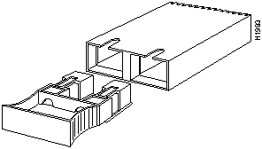
Figure 19 : Installing the CAB-ATM-DS3/E3 Cable and EMI Filter Clip Assembly
After you install the AIP, verify the installation by observing the LED states and the console display. When the system has reinitialized all interfaces, the enabled LED on the AIP and on all interface processors should go on. The console screen will also display a message as the system discovers each interface during its reinitialization. After system initialization, the enabled LED, which is present on all interface processors, goes on to indicate that the AIP is enabled for operation.
The following conditions must be met before the AIP is enabled:
If any of these conditions is not met, the enabled LED does not go on.
The three LEDs above the ATM port (see Figure 1) indicate the following:
When you remove and replace CxBus interface processors, the system provides status messages on the console screen. The messages are for information only. The following sample display shows the events logged by the system as an AIP was removed from slot 1; the system then reinitialized the remaining interface processors and marked as down the AIP that was removed from slot 1. When the AIP was reinserted, the system marked the interface as up again because the ATM interface was not shut down before the AIP was removed.
When a new AIP is inserted or when an AIP is moved to a new slot, the system recognizes the new ATM interface, but leaves the interface in a down state until you configure the interface. Change the state to up with the configure command. The following example display shows the events logged by the system as a new AIP is inserted in slot 3:
Verify that the AIP is installed correctly as follows:
If an error message displays on the console terminal, refer to the appropriate software publication for error message definitions. If you experience other problems that you are unable to solve, contact a customer service representative for assistance.
This completes the AIP installation. If you installed a new AIP, you must now configure the new ATM interface, as described in the following section.
Configuration of the AIP is a two step process: you will configure the AIP, then you will configure the ATM switch.
To configure ATM, complete the following tasks. The first two tasks are required, and then you must configure at least one PVC or SVC. The VC options you configure must match in three places: on the router, on the ATM switch, and at the remote end of the PVC or SVC connection.
On power up, a new AIP is shut down. To enable the AIP, you must enter the no shutdown command in the configuration mode. (See the section "Using the Configure Command," which follows.
If you installed a new AIP or want to change the configuration of an existing interface, you must enter the configuration mode. When the AIP is enabled (taken out of shutdown) with no additional arguments, the default interface configuration file parameters are as listed in Table 5.
Table 5 : AIP Configuration Default Values
After you verify that the new AIP is installed correctly (the enabled LED goes on), you can use the configure command to configure the new ATM interface. Be prepared with the information you will need, such as the interface IP address, MTU size, AAL mode, and desired rate queues.
Following are instructions for a basic configuration: enabling an interface and specifying IP routing. You might also need to enter other configuration subcommands, depending on the requirements for your system configuration and the protocols you plan to route on the interface. For complete descriptions of configuration subcommands and the configuration options available for ATM, refer to the appropriate router system software publications.
The Cisco 7000 series routers identify an interface address by its interface processor slot number (slots 0 to 4) and port number (port numbers 0 to 7, depending on the interface processor type) in the format slot/port. Because each AIP contains a single ATM interface, the port number is always 0. For example, the slot/port address of an ATM interface on an AIP installed in interface processor slot 1 would be 1/0.
The following steps describe a basic configuration. Before using the configure command, you must enter the privileged level of the EXEC command interpreter with the enable command. The system will prompt you for a password if one is set. Press the Return key after each configuration step unless otherwise noted.
A rate queue defines the maximum speed at which an individual VC transmits data to a remote ATM host.
There are no default rate queues. Every VC must be associated with one rate queue. The AIP supports up to eight different peak rates. The peak rate is the maximum rate, in kilobits per second, at which a VC can transmit. After attachment to this rate queue, the VC is assumed to have its peak rate set to that of the rate queue.
You can configure each rate queue independently to a portion of the overall bandwidth available on the ATM link. The combined bandwidths of all rate queues should not exceed the total bandwidth available for the AIP physical layer interface. The total bandwidth depends on the PLIM (see the section entitled "AIP Interface Types" on page 13 of this publication).
The rate queues are broken into a high (0 through 3) and low (4 through 7) bank. When the rate queues are configured, the AIP will service the high priority banks until they are empty and then service the low priority banks.
VCs get the entire bandwidth of the associated rate queue. If over subscription occurs, the other rate queues in bank A will miss the service opportunities. In the worst case, a 10-Mbps rate queue will take 100 Mbps if there are 10 VCs attached to it and all of them have packets to send at the same time.
To configure rate queue 1 at 10 Mbps, use the atm rate-queue queuenumber rate command in interface configuration mode as follows:
where the queue number is in the range of 0 to 7 and the rate (in Mbps) in the range of 1 to 155. The no form of the command removes the rate queue.
You must create a rate queue before you can create PVCs or SVCs. If all rate queues are unconfigured, a warning message will appear, as follows:
If the combined queue rates exceed the AIP physical layer interface bandwidth maximum, a warning message will appear, as follows:
The AIP default values may be changed to match your network environment. Perform the tasks in the following sections if you need to customize the AIP:
The AIP interface is referred to as atm in the RP configuration commands. An interface is created for each AIP found in the system at reset time. To select a specific AIP interface, use the interface atm command, as follows:
where n is the slot number and i is the interface number.
To set the maximum transmission unit (MTU) size, use the following command:
where bytes is in the range of 64 through 9188 bytes and the default is 4470 bytes. (4470 bytes exactly matches FDDI and HSSI interfaces for autonomous switching.) The no form of the command restores the default.
In STM-1 mode, the AIP sends idle cells for cell-rate decoupling. In STS-3C mode, the AIP sends unassigned cells for cell-rate decoupling. The default SONET setting is STS-3C. To configure for STM-1, use the following command:
To change back to STS-3C, use the no atm sonet stm-1 command.
Configuring an ATM Interface for Local Loopback
To configure an ATM interface for local loopback (useful for checking that the AIP is working), use the following command:
The no form of the command turns off loopback.
Setting the Reassembly Buffers
The atm rxbuff command sets the maximum number of reassemblies that the AIP can perform simultaneously. The AIP allows up 512 simultaneous reassemblies; the default is 256. The no form of the command restores the default.
To set the number of transmit buffers for simultaneous fragmentation, use the following command:
where n is in the range 0 to 512. The default is 256. The no form of the command restores the default.
Setting the Source of the Transmit Clock
By default, the AIP uses the recovered receive clock to provide transmit clocking. To specify that the AIP generates the transmit clock internally for SONET, E3, and DS3 PLIM operation, use the following command:
A VC is a point-to-point connection between remote hosts and routers. A VC is established for each ATM end node with which the router communicates. The characteristics of the VC are established when the VC is created and include the following:
Each VC supports the following router functions:
By default, fast switching is enabled on all AIP interfaces. These switching features can be turned off with interface configuration commands. Autonomous switching must be explicitly enabled per interface.
Permanent Virtual Circuit (PVC) Configuration
All PVCs, configured into the router, remain active until the circuit is removed from the configuration. The PVCs also require a permanent connection to the ATM switch.
All virtual circuit characteristics apply to PVCs. When a PVC is configured, all the configuration options are passed on to the AIP. These PVCs are writable into the nonvolatile RAM (NVRAM) as part of the RP configuration and are used when the RP image is reloaded.
Some ATM switches have point-to-multipoint PVCs that do the equivalent of broadcasting. If a point-to-multipoint PVC exists, then that PVC can be used as the sole broadcast PVC for all multicast requests.
To configure a PVC, you must perform the following tasks:
When you create a PVC, you create a virtual circuit descriptor (VCD) and attach it to the VPI and VCI. A VCD is an AIP-specific mechanism that identifies to the AIP which VPI/VCI to use for a particular packet. The AIP requires this feature to manage the packets, for transmission. The number chosen for the VCD is independent of the VPI/VCI used.
When you create a PVC, you also specify the AAL and encapsulation. A rate queue is used that matches the peak and average rate selections, which are specified in kilobits per second. Omitting a peak and average value causes the PVC to be connected to the highest bandwidth rate queue available. In that case, the peak and average values are equal.
To create a PVC on the AIP interface, use the atm pvc command. To remove a PVC, use the no form of this command.
For example:
vcd---A per-AIP unique index value describing this VC in the range of 1 to MAXVC.
vpi---The ATM network VPI to use for this VC in the range of 0 through 255.
vci---The ATM network VCI to use for this VC in the range of 0 through 65,535.
encapsulation---The encapsulation type to use on this VC from the following:
protocol-type-for-mux---A protocol type compatible with the MUX is required from the following protocols: ip, decnet, novell, vines, xns.
peak-rate---(Optional) The maximum rate, in Kbps, at which this VC can transmit.
average-rate---(Optional) The average rate, in Kbps, at which this VC will transmit.
cell quota---(Optional) The cell-quota is an integer value, in the range 1 through 2047, describing the maximum number of credits that a VC can accumulate. The AIP makes use of this in multiples of 32 cells. Every cell transfer consumes one cell credit. One cell transfer credit is issued to a VC in the average rate speed.
The atm pvc command creates PVC n and attaches the PVC to VPI and VCI. The AAL used is specified by aal and encapsulation by encap. A rate queue is used that matches the peak and average (avg) rate selection. The peak and avg rate selection values are specified in Kbps. Not specifying a peak and avg value causes the PVC to default to the highest bandwidth rate queue available.
The defaults for peak-rate and average-rate is that peak = average, and the PVC is automatically connected to the highest bandwidth rate queue available. A VCD is an AIP specific mechanism that identifies to the AIP which VPI/VCI to use for a particular packet. The AIP requires this feature to manage the packets for transmission.
The vp filter (vp_filter) configures the hex value used in the vp filter register in the reassembly operation. When a cell is received, the right half (most-significant byte) of the filter is exclusively NORed with the incoming VPI. The result is then ORed with the left half (least-significant byte) of the filter (the mask). If the result is all ones, then reassembly is done using the VCI/MID table. Otherwise, reassembly is done using the VPI/VCI table. The vp filter mechanism allows a way of specifying which VPI (or range of VPIs) will be used for AAL3/4 processing, all other VPIs mapping to AAL5 processing. In the case where only AAL5 processing is desired, the vp filter should be set to the default VPI of 0x7B (hexadecimal). AAL5 processing will be performed on the first 127 VPIs in that case. Currently you can only configure one VPI for all the AAL3/4 packets.
Examples follow:
All incoming cells with VPI = 1 will be reassembled via AAL3/4 processing. AAL3/4 is supported with IOS Release 10.2 and later.
All incoming cells with VPI = 0 will be reassembled via AAL3/4 processing. All other cells will be reassembled via AAL5 processing.
Mapping a Protocol Address to a PVC
The initial release of IOS Release 10.0 will support a mapping scheme that identifies the ATM address of remote hosts/routers. This address can be specified either as a virtual circuit descriptor (VCD) for a PVC or an NSAP address for SVC operation.
Enter mapping commands as groups; multiple map entries can exist in one map list. First create a map list, then associate the list with an interface.
Enter the map-list name command; then enter the protocol, protocol address, and other variables, as follows:
The broadcast keyword specifies that this map entry receives the corresponding protocol broadcast requests to the interface (for example, any network routing protocol updates). If you do not specify broadcast, the ATM software is prevented from sending routing protocol updates to the remote hosts.
After you create the map list, specify the ATM interface to which it applies with the interface command, as follows:
Associate the map list to an interface with the following command:
You can create multiple map lists, but only one map list can be associated with an interface. Different map lists can be associated with different interfaces. The following is an example of the mapping a list to an interface:
The AIP will maintain a count of certain errors. In addition to keeping a count of these errors, the AIP will also snapshot the last VCI/VPI that caused the error. Each AIP error counter is 16 bits.
Errors include the following:
After configuring the new interface, use the show commands to display the status of the new interface or all interfaces.
ATM show commands are available to display the current state of the ATM network and the connected VCs.
To show current VCs and traffic information, use the following command:
Specifying a VCD will display specific information about that VCD.
To show current information about an ATM interface, use the following command:
The show atm int interface command will display ATM specific information about an interface.
To show current ATM traffic, use the following command:
The show atm traffic command displays global traffic information to and from all ATM networks connected to the router.
To show the current ATM mapping, use the following command:
The show atm map command displays the active list of ATM static maps to remote hosts on an ATM network.
Other Commands That Display AIP Information
Following are descriptions and examples of the show commands that display AIP information.
The following debug commands are available to aid in solving ATM network problems:
To create a dump of all protocol packets, use the following command:
The debug atm packet command will display the contents of the SNAP/NLPID/SMDS header followed by the first 40 bytes of a packet in hexadecimal format.
To display errors, use the following command:
The debug atm errors command displays information from all detected ATM errors. This includes such errors as encapsulation failures and errors during ATM configuration.
To display ATM events, use the following command:
The debug atm events command displays event changes to the AIP. Reset, VC configurations, AIP configurations, and PLIM failures are displayed here.
To display information about OAM cells, use the following command:
The debug atm oam command displays the contents of OAM cells as they arrive from the network.
After a debug command is used, turn off debugging with the no debug command.
The following lists the possible ATM error messages displayed when you enter the debug atm event command.
aip_disable(ATM2/0): state=1
config(ATM2/0)
aip_enable(ATM2/0)
aip_love_note(ATM2/0): asr=0xaaaa
All other values of the ASR are meaningless and discarded. The love note messages only show up if debug atm event is turned on.
aip_cstate(ATM2/0): state=1
aip_setup_vc(ATM2/0): vc:1 vpi:0 vci:7
aip_setup_vc(ATM2/0): vc1 creation delayed, AIP config. in progress
aip_teardown_vc(ATM2/0): vc:1 vpi:0 vci:
aip_enable(ATM2/0): restarting VCs: 5
The following are the possible error messages displayed when you enter the debug atm errors command:
aip_love_note(ATM2/0): UNKNOWN asr=0x0000
aip_setup_vc(ATM2/0): TIQ err. VC 1 peak 1000 avg. 1 rateq rate 2
aip_setup_vc(ATM2/): CQ err. VC 1 CQ=2048 MTU=256000
aip_setup_vc(ATM2/0): Return value 0
aip_teardown_vc(ATM2/0): Return value 0
ATM(ATM2/0): Config. scaler error. RateQ 1, rate 1
aip_raw_input(ATM2/0): bad OAM type 0xaaaa
aip_raw_input(ATM2/0): bad OAM function 0xaaaa
atm_pakalign(ATM2/0): Invalid VC(65535) received, type=0xaaaa
atm_pakalign(ATM2/0): VC(1) NOT configured, type=0xaaaa
ATM(ATM2/0): Encapsulation error, link=0xaaaa, host=0xaaaa
ATM(ATM2/0: Encapsulation error, VC=1 not connected
For detailed configuration examples, refer to the router software publications. The following sections contain examples of ATM interface configurations:
Example of PVCs with AAL5 and LLC/SNAP Encapsulation
The following example creates PVC 5 on ATM interface 3/0 using LLC/SNAP encapsulation over AAL5. ATM interface 3/0 (IP address 1.1.1.1) connects with the ATM interface (IP address 1.1.1.5) at the other end of the connection. The static map list named atm declares that the next node is a broadcast point for multicast packets from IP.
The following example is of a typical ATM configuration for a PVC:
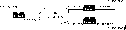
Example of PVCs in a Fully Meshed Network
Figure 20 illustrates a fully meshed network. The configurations for Routers A, B, and C follow. In this example, the routers are configured to use PVCs. Fully meshed indicates that any workstation can communicate with any other workstation. Note that the two map-list statements configured in Router A identify the ATM addresses of Routers B and C. The two map-list statements in Router B identify the ATM addresses of Routers A and C. The two map list statements in Router C identify the ATM addresses of Routers A and B.
Figure 20 : Fully Meshed ATM Configuration Example
Example of SVCs in a Fully Meshed Network
The following example is also a configuration for the fully meshed network shown in Figure 20, but using SVCs. PVC 1 is the signaling PVC.
Example of Connecting Two AIPs Back to Back
Two routers, each containing an AIP, can be connected directly back to back with a standard cable, which allows you to verify the operation of the ATM port or to directly link the routers in order to build a larger node.
Define Cisco 7000 interfaces by interface type and physical slot/port location. The output of the show interfaces command displays the logical unit number in the router and the physical slot/port location in the Cisco 7000. For complete configuration descriptions and examples, refer to the router software publications appropriate for your IOS release.
To connect two routers, attach the cable between the ATM port on each.
By default, the AIP expects a connected ATM switch to provide transmit clocking. To specify that the AIP generates the transmit clock internally for SONET, E3, or DS3 PLIM operation, add the atm clock internal command to your configuration.
Following is an example of configuration file commands for two routers connected through their SONET, E3, or DS3 interfaces:
First router:
Second router
Cisco Information Online (CIO) is Cisco Systems' primary, real-time support channel. Maintenance customers and partners can self-register on CIO to obtain additional content and services.
Available 24 hours a day, 7 days a week, CIO provides a wealth of standard and value-added services to Cisco's customers and business partners. CIO services include product information, software updates, release notes, technical tips, the Bug Navigator, configuration notes, brochures, descriptions of service offerings, and download access to public and authorized files.
CIO serves a wide variety of users through two interfaces that are updated and enhanced simultaneously---a character-based version and a multimedia version that resides on the World Wide Web (WWW). The character-based CIO (called "CIO Classic") supports Zmodem, Kermit, Xmodem, FTP, Internet e-mail, and fax download options, and is excellent for quick access to information over lower bandwidths. The WWW version of CIO provides richly formatted documents with photographs, figures, graphics, and video, as well as hyperlinks to related information.
You can access CIO in the following ways:
For a copy of CIO's Frequently Asked Questions (FAQ), contact
Copyright 1988-1996 © Cisco Systems Inc.
![]()
![]()
![]()
Transceiver Type
Maximum Distance between Stations1
Single-mode
Up to 9 miles (15 kilometers)
Multimode
Up to 1.5 miles (3 kilometers)
1 Table1 gives typical results. You should use the power budget calculations to determine the actual distances.
Limits
Single-Mode
Multimode
Attenuation
0.5 dB
1.0 dB/km
Dispersion
No limit
500 MHzkm1
1 The product of bandwidth and distance must be less than 500 MHzkm.
Link Loss Factor
Estimate of Link Loss Value
Higher order mode losses
0.5 dB
Clock recovery module
1 dB
Modal and chromatic dispersion
Dependent on fiber and wavelength used
Connector
0.5 dB
Splice
0.5 dB
Fiber attenuation
1 dB/km
Single-Mode
Multimode
PT
--18.5
--15
PR
--30
--28
PB
--11.5
--13


![]()
![]()


![]()
Router> show version
GS Software (GS7), Version 10.0
Copyright (c) 1986-1994 by cisco Systems, Inc.
Compiled Thu 05-Feb-93 14:16
(remainder of displayed text omitted from example)
router# show cont cbus
Switch Processor 5, hardware version 11.1, microcode version 170.46
 Microcode loaded from system
  512 Kbytes of main memory, 128 Kbytes cache memory
  60 1520 byte buffers, 91 4496 byte buffers
  Restarts: 0 line down, 0 hung output, 0 controller error
 AIP 4, hardware version 1.0, microcode version 170.30
  Microcode loaded from system
  Interface 32 - ATM4/0, PLIM is 4B5B(100Mbps)
    15 buffer RX queue threshold, 36 buffer TX queue limit, buffer size 4496
    ift 0007, rql 12, tq 0000 0620, tql 36
    Transmitter delay is 0 microseconds
Router# show flash
4096K bytes of flash memory on embedded flash (in RP1).
file     offset     length        name
  0     0x80        53364       aip1-1
  1     0xD134      55410       sp1-2
  [4085336/4194304 bytes free]
![]()
![]()
![]()
![]()
![]()
![]()
![]()
![]()
![]()
![]()
Router#

%OIR-6-REMCARD: Card removed from slot 1, interfaces disabled
%LINK-5-CHANGED: Interface ATM1/0, changed state to administratively down

Router#
%OIR-6-INSCARD: Card inserted in slot 1, interfaces administratively shut down
%LINK-5-CHANGED: Interface ATM1/0, changed state to up
Router#
%OIR-6-INSCARD: Card inserted in slot 3, interfaces administratively shut down
Parameter
Configuration Command
Default Value
MTU
mtu bytes
4470 bytes
Exception queue buffers
atm exception-queue
32
ATM virtual path filter
atm vp-filter hexvalue
0x7B (hexadecimal)
Receive buffers
atm rxbuff
256
Transmit buffers
atm txbuff
256
Maximum number of VCs
atm maxvc
2048
AAL encapsulation
atm aal aal5
AAL5
ATM raw cell queue size
atm rawq-size
32
ATM VCs per VP
atm vc-per-vp
1024
Router#
configure
terminal <
CR>
Router(config)# interface
atm 1/0
Router(config)# ip address 10.1.2.3 255.255.255.0
Router(config)# no shutdown
Router#
write memory
Router(config-if)# atm rate-queue 1 10
%WARNING:(ATM4/0): All rate queues are disabled
%WARNING(ATM4/0): Total rate queue allocation nMbps ex ceeds maximum of nMbps
interface atm n / i
mtu bytes
no mtu
atm sonet stm-1
loopback plim
no loopback plim
atm txbuff n
no atm txbuff
atm clock internal
atm pvc vcd vpi vci aal-encap [peak] [average] [cell-quota]
no atm pvc vcd
Router(config)# interface atm 2/0
Router(config-if)# atm pvc 2048 255 128 aal5snap 10 10 2046
aal5snap---LLC/SNAP precedes the protocol datagram.
aal5nlpid---NLPID precedes the protocol datagram.
aal34smds---SMDS framing precedes the protocol datagram.
qsaal---A signaling type VC.
atm vp-filter 1
atm vp-filter 0
map-list name

protocol protocol address atm-vc vcd | atm-nsap nsap [broadcast]
interface atm slot/port
map-group name
interface atm4/0
ip address 131.108.168.110 255.255.255.0
map-group atm
atm rate-queue 1 100
atm pvc 1 0 8 aal5snap
atm pvc 2 0 9 aal5mux decnet
decnet cost 1
!
map-list atm
ip 131.108.168.112 atm-vc 1 broadcast
decnet 10.2 atm-vc 2 broadcast
show atm vc [vcd]
show atm int interface
show atm traffic
show atm map
router# show cont cbus
Switch Processor 5, hardware version 11.1, microcode version 170.46
  Microcode loaded from system
  512 Kbytes of main memory, 128 Kbytes cache memory
  60 1520 byte buffers, 91 4496 byte buffers
  Restarts: 0 line down, 0 hung output, 0 controller error
 AIP 4, hardware version 1.0, microcode version 170.30
  Microcode loaded from system
  Interface 32 - ATM4/0, PLIM is 4B5B(100Mbps)
    15 buffer RX queue threshold, 36 buffer TX queue limit, buffer size 4496
    ift 0007, rql 12, tq 0000 0620, tql 36
    Transmitter delay is 0 microseconds
router# show atm vc
Intfc.   VCD   VPI   VCI   Input   Output  AAL/Encaps    Peak  Avg.  Burst
ATM4/0.1 1     1     1     305     0       AAL3/4-SMDS   0     0     0
ATM4/0   2     2     2     951     0       AAL5-SNAP     0     0     0
ATM4/0   3     3     3     0       0       AAL5-SNAP     0     0     0
ATM4/0   4     4     4     162     0       AAL5-MUX      0     0     0
ATM4/0   6     6     6     2722    0       AAL5-SNAP     0     0     0
ATM4/0   7     7     7     733     0       AAL5-SNAP     0     0     0
router# show atm vc 4
ATM4/0: VCD: 4, VPI: 4, VCI: 4, etype:0xBAD, AAL5 - MUX, Flags: 0x34
PeakRate: 0, Average Rate: 0, Burst: 0 *32cells, Vcmode: 0xE200
InPkts: 164, OutPkts: 0, InFast: 0, OutFast: 0, Broadcasts: 0
Router# show atm vc 1

ATM4/0.1: VCD: 1, VPI: 0, VCI: 1, etype:0x1, AAL3/4 - SMDS, Flags: 0x35
PeakRate: 0, Average Rate: 0, Burst: 0 *32cells, VCmode: 0xE200
MID start: 1, MID end: 16
InPkts: 0, OutPkts: 0, InFast: 0, Broadcasts: 0
router# show atm int atm 4/0
ATM interface ATM4/0:
AAL enabled:  AAL5, Maximum VCs: 1024, Current VCs: 6
Tx buffers 256, Rx buffers 256, Exception Queue: 32, Raw Queue: 32
VP Filter: 0x7B, VCIs per VPI: 1024
PLIM Type:4B5B - 100Mbps, No Framing, TX clocking: LINE
4897 input, 2900 output, 0 IN fast, 0 OUT fast
Rate-Queue 1 set to 100Mbps, reg=0x4EA
Config. is ACTIVE
router# show atm map
Map list atm:

vines 3004B310:0001 maps to VC 4, broadcast
ip 131.108.168.110 maps to VC 1, broadcast
clns 47.0004.0001.0000.0c00.6e26.00 maps to VC 6, broadcast
appletalk 10.1 maps to VC 7, broadcast
decnet 10.1 maps to VC 2, broadcast
router# show atm traffic
4915 Input packets
0 Output packets
2913 Broadcast packets
0 Packets for non-existent VC
0 Packets with CRC errors
0 OAM cells received
0 Cells lost
Router> show version

GS Software (GS7), Version 10.0
Copyright (c) 1986-1993 by cisco Systems, Inc.
Compiled Mon 11-Jan-93 14:44

System Bootstrap, Version 4.6(1)

Current date and time is Fri 2-26-1994 2:18:52
Boot date and time is Fri 1-29-1994 11:42:38
Router uptime is 6 weeks, 6 days, 14 hours, 36 minutes
System restarted by power-on
Running default software
Network configuration file is "Router", booted via tftp from 131.109.2.333

RP1 (68040) processor with 16384K bytes of memory.
X.25 software.
Bridging software.
1 Switch Processor.
1 TRIP controller (4 Token Ring).
4 Token Ring/IEEE 802.5 interface.
1 AIP controller (1(ATM)
1 ATM network interface
4096K bytes of flash memory on embedded flash (in RP1).
Configuration register is 0x0
   (display text omitted)
Router# write term
interface atm2/0
ip address 131.110.162.110 255.255.255.0
atm rate-queue 1 100
atm rate-queue 2 5
atm pvc 1 1 1 aal5mux ip
atm pvc 3 3 3 aal5snap
atm pvc 4 4 5 aal5snap 4000 3000
appletalk address 10.1
appletalk zone atm
debug atm packet
debug atm errors
debug atm events
debug atm oam
RESET(ATM2/0): PLIM type is 0, Rate is 0Mbps
F4 SEGMENT
F4 END-to-END
F5 SEGMENT
F5 END-to-END
ATM(ATM2/0): VC(1) Bad SAP received
ATM(ATM2/0): Bad VC(1) encapsulation configured
interface atm 3/0
ip address 1.1.1.1 255.255.255.0
atm rate-queue 1 100
atm pvc 5 0 10 aal5snap
ip route-cache cbus
map-group atm

map-list atm
ip 1.1.1.5 atm-vc 5 broadcast
interface atm4/0
ip address 131.108.168.112 255.255.255.0
map-group atm
atm rate-queue 1 100
atm maxvc 512
atm pvc 1 1 1 aal5snap
atm pvc 2 2 2 aal5snap
atm pvc 6 6 6 aal5snap
atm pvc 7 7 7 aal5snap
decnet cost 1
clns router iso-igrp comet
!
router iso-igrp comet
net 47.0004.0001.0000.0c00.6666.00
!
router igrp 109
network 131.108.0.0
!
ip domain-name CISCO.COM
!
map-list atm
ip 131.108.168.110 atm-vc 1 broadcast
clns 47.0004.0001.0000.0c00.6e26.00 atm-vc 6 broadcast
decnet 10.1 atm-vc 2 broadcast
ip routing
!
interface atm 4/0
ip address 131.108.168.1 255.255.255.0
atm rate-queue 1 100
atm pvc 1 0 10 aal5snap
atm pvc 2 0 20 aal5snap
map-group test-a
!
map-list test-a
ip 131.108.168.2 atm-vc 1 broadcast
ip 131.108.168.3 atm-vc 2 broadcast
ip routing
!
interface atm 2/0
ip address 131.108.168.2 255.255.255.0
atm rate-queue 1 100
atm pvc 1 0 20 aal5snap
atm pvc 2 0 21 aal5snap
map-group test-b
!
map-list test-b
ip 131.108.168.1 atm-vc 1 broadcast
ip 131.108.168.3 atm-vc 2 broadcast
ip routing
!
interface atm 4/0
ip address 131.108.168.3 255.255.255.0
atm rate-queue 1 100
atm pvc 2 0 21 aal5snap
atm pvc 4 0 22 aal5snap
map-group test-c
!
map-list test-c
ip 131.108.168.1 atm-vc 2 broadcast
ip 131.108.168.2 atm-vc 4 broadcast
interface atm 4/0
ip address 131.108.168.1 255.255.255.0
map-group atm
atm nsap-address AB.CDEF.01.234567.890A.BCDE.F012.3456.7890.1234.12
atm rate-queue 1 100
atm maxvc 1024
atm pvc 1 0 5 qsaal
!
map-list atm
ip 131.108.168.2 atm-nsap BC.CDEF.01.234567.890A.BCDE.F012.3456.7890.1334.13
ip 131.108.168.3 atm-nsap BC.CDEF.01.234567.890A.BCDE.F012.3456.7890.1224.12
interface atm 2/0
ip address 131.108.168.2 255.255.255.0
map-group atm
atm nsap-address BC.CDEF.01.234567.890A.BCDE.F012.3456.7890.1334.13
atm rate-queue 1 100
atm maxvc 1024
atm pvc 1 0 5 qsaal
!
map-list atm
ip 131.108.168.1 atm-nsap AB.CDEF.01.234567.890A.BCDE.F012.3456.7890.1234.12
ip 131.108.168.3 atm-nsap BC.CDEF.01.234567.890A.BCDE.F012.3456.7890.1224.12
interface atm 4/0
ip address 131.108.168.3 255.255.255.0
map-group atm
atm nsap-address BC.CDEF.01.234567.890A.BCDE.F012.3456.7890.1224.12
atm rate-queue 1 100
atm maxvc 1024
atm pvc 1 0 5 qsaal
!
map-list atm
ip 131.108.168.1 atm-nsap AB.CDEF.01.234567.890A.BCDE.F012.3456.7890.1234.12
ip 131.108.168.2 atm-nsap BC.CDEF.01.234567.890A.BCDE.F012.3456.7890.1334.13
interface ATM3/0
ip address 1.0.0.1 255.0.0.0
no keepalive
map-group atm-in
atm clock internal
atm rate-queue 2 34
atm pvc 1 1 5 aal5snap
!
map-list atm-in
ip 1.0.0.2 atm-vc 1 broadcast
interface ATM3/0
ip address 1.0.0.2 255.0.0.0
no keepalive
map-group atm-in
atm clock internal
atm rate-queue 2 34
atm pvc 1 1 5 aal5snap
!
map-list atm-in
ip 1.0.0.1 atm-vc 1 broadcast
http://www.cisco.com
cio.cisco.com
ciohelp@cisco.com.
For additional information, contact
cioteam@cisco.com.
tac@cisco.com.
To obtain general information about Cisco Systems, Cisco products, or upgrades, contact 800 553-6387, 408 526-7208, or
csrep@cisco.com.
![]()
![]()
![]()
![]()
![]()
![]()
![]()
![]()