|
|

Upgrading Software and Microcode in Cisco 7000 Series and Cisco 7500 Series Routers
The Cisco 7000 series and Cisco 7500 series supports downloadable software and microcode for most new images; however, some exceptions require read-only memory (ROM) replacement in order for the router to boot and operate properly. This document provides instructions for upgrading with both types of media---floppy disk and ROM.
This publication describes the following tasks:
Routers also can netboot from a TFTP file server directly to central processing unit (CPU)--local random-access memory (RAM) regardless of whether it has Flash memory. For procedures, refer to the appropriate software configuration documentation listed in the section "If You Need More Information" on page 54. Instructions for contacting technical assistance are provided at the end of this document, in the section "Cisco Information Online (CIO)."
The information in this publication is organized within the following sections:
Overview of Image Distribution and Upgrade Methods
Cisco 7000 series and Cisco 7500 series routers feature downloadable software and microcode for most new images. Also, microcode images are bundled with the system code, so individual microcode upgrades are no longer necessary.
Downloadable microcode allows you to download new images over the network, store the images in the router's Flash memory, and load images from Flash at system startup without having to physically access the router. Although for most upgrades you can configure the system to load newer images from Flash memory files to override the default ROM images, some exceptions require ROM replacement to ensure proper startup and operation.
All Cisco 7000 series and Cisco 7500 series software and microcode upgrades that were released prior to SP Microcode Version 1.4 (in September 1993) were distributed on floppy disk and could be stored in, and loaded from, Flash memory. SP Microcode Version 1.4 was the first microcode upgrade to be distributed on ROM. (Because the system software accesses the SP microcode during the boot process, SP Microcode Version 1.4 must reside in ROM; it cannot be stored and loaded from a Flash file.)
Bundled images include the latest system software image and the latest available microcode image for the following processor types: Asynchronous Transfer Mode (ATM) Interface Processor (AIP), Channel Interface Processor (CIP), Ethernet Interface Processor (EIP), Fiber Distributed Data Interface (FDDI) Interface Processor (FIP), Fast Ethernet Interface Processor (FEIP), Fast Serial Interface Processor (FSIP), High-Speed Serial Interface (HSSI) Interface Processor (HIP), Multichannel Interface Processor (MIP), SP, SSP, and Token Ring Interface Processor (TRIP).
The upgrade procedure for bundled images is the same as that for previous upgrades; bundled images reside either in Flash memory or in ROM. When the system boots from a bundled image, a utility scans the installed processors to determine compatibility with the new microcode, and (if there are no conflicts) loads the microcode images automatically. A new command, show microcode, lists all of the microcode images that are bundled with the system software image. (For a brief description of the show microcode command, refer to "Listing the Bundled Microcode Versions" on page 28; for a complete description, refer to the appropriate software release note.)
Depending upon the type of media in your upgrade kit, proceed as follows:
Review the entire section before beginning either of these procedures to ensure that you are aware of any safety considerations or system prerequisites.
Upgrading from Floppy Disks or TFTP Servers
This section describes the procedures for upgrading system software or microcode from a floppy disk by copying the new image to a TFTP server, then loading the new image from the TFTP server to the Flash memory on one or more routers. When ROM replacement is not required, this procedure allows you to upgrade all of the routers in your network remotely, without having to physically access the router to replace components.
Cisco 7000 series and Cisco 7500 series routers also can netboot from a TFTP file server directly to CPU-local RAM, which does not require storing the image in Flash memory. The procedure is described in the appropriate router software configuration documentation. If you received an upgrade kit with replacement ROMs for the system software or microcode, refer to "Upgrading Software and Microcode with Replacement ROMs" on page 29 for instructions.
To successfully upgrade the system software or microcode, you should observe the following prerequisites and caveats.
This section lists the general steps required to upgrade from a new image on floppy disk. The sections that follow describe these steps in greater detail.
Installing the New Image onto Your TFTP Server
This section describes how to use the installation program on the disk to install the new image onto your DOS-based PC or your desktop SPARCstation. Refer to the online README file on the upgrade disk for details about the new image. The README file lists details such as the product number, image types, file sizes, and checksums of the images.
Installing New Images onto a DOS-Based PC
To copy the new image into the appropriate directory on the PC you plan to use as the TFTP server, follow this procedure. Allow five minutes to complete this procedure.
Following is the procedure for installing new images onto a DOS-based personal computer (PC):
Installing New Images onto a Sun Workstation
The following procedure describes how to install the new image onto a desktop SPARCstation with SunOS 4.1.x. The workstation must have a 3.5-inch, 1.44-MB floppy disk drive. Allow ten minutes to complete this procedure.
You must have superuser access to install the new image on a UNIX system.
Use the following procedure to create a mount point and install the new image on your TFTP server. Note that filenames are case sensitive.
Proceed to the next section, "Making Network Connections."
This section describes the following topics:
After installing the TCP/IP software you will use to copy the new image to the routers on your network, make sure it functions properly by following this procedure:
If you are using PC/TCP Network Software for DOS from FTP Software, Inc., you can verify the appropriate driver and IP address by entering the following command:
You can verify your IP configuration by entering the following command:
If you are using Chameleon TCP/IP for Windows from NetManage, Inc., run its setup program to verify that you are using the appropriate driver and have configured the TCP/IP software properly.
This section describes how to set up your UNIX system or PC as a TFTP server and start a TFTP session with the router you want to upgrade remotely.
If you are using a PC and do not already have TFTP software, we recommend the following two TCP/IP software packages:
The section "Prerequisites and Caveats" on page 4 lists some issues to keep in mind while installing the software.
Setting Up TFTP on a Sun Workstation
To set up the Sun system as a TFTP server, you must verify that the TFTP daemon is enabled, the TFTP environment variable is set correctly, and a tftpboot directory exists. To see if TFTP is enabled, enter the following command:
If the TFTP daemon is already enabled, proceed to "Creating a tftpboot Directory" on page 12.
The TFTP daemon (tftpd) permits the system to be a TFTP server. If you are using the standard Sun software, verify that tftpd is enabled by completing the following steps:
If there is no output, tftpd is not enabled. For additional information about TFTP, refer to the UNIX man pages about tftp and tftpd.
The tftpboot directory can be used to save and store configuration files that are loaded to a device. Device configuration files can be saved as TFTP boot files.
Creating a tftpboot Directory on a Sun Workstation
You must have superuser access to perform the following steps. These steps describe how to create a tftpboot directory.
Creating a tftpboot Directory on a PC
To create a new directory on a PC, enter the following command:
After completing all the preparations required to set up your Sun workstation or PC as a TFTP server, refer to "Testing the TCP/IP Software" on page 10.
You must be able to issue commands to the router you plan to upgrade. For example, this publication tells you to issue a command to download an image from the TFTP server to the router. If you have a console port connection to the router, you need not invoke a Telnet session.
If you do not have a console port connection to the router, you must establish a Telnet session with it so that you can issue commands.
You can set up a Telnet session from a Sun workstation or from a PC.
This section presents the following topics:
Backing Up the Current Contents of Flash Memory
If your system is currently running from a system software image stored in Flash memory and you do not already have the image backed up on a TFTP server, make sure you back up this image before installing the new image. You can also use this procedure to back up other files you have stored in Flash.
Also back up any microcode images stored in Flash memory that you want to keep. Microcode upgrades for most Cisco 7000 series and Cisco 7500 series interface processors have been released, and all except SP Microcode Version 1.4 were distributed on floppy disk. Because microcode is now bundled with system software images, you no longer need to save the individual microcode images. However, until you verify that the new bundled image is loaded and running successfully, we recommend that you back up all working files that are currently stored in Flash. You can delete the backups after you install and verify the new image.
First, you must know the exact spelling of the name of each image that you will back up. To learn the image name, issue the show flash all command. The following sample output shows one system software image (7k10390z) and one microcode image (fip1-1).
When you back up the image, use the exact filename from the show flash all command screen.
Copying the Image from Flash Memory to the TFTP Server
To copy an image from Flash memory to a TFTP server, use the copy flash tftp command:
The router prompts you for the IP address of the TFTP server and the name of the image file you are copying to the server. A sample of the output for this command using IP address 131.108.10.6 and filename 7k91720z follows:
Use the image you backed up to the TFTP server in case the upgrade image becomes damaged.
Copying the Image from a TFTP Server to Flash Memory
The copy tftp flash command retrieves an image from a TFTP server and copies (writes) the image into the router's Flash memory. The TFTP server can be another Cisco router serving ROM or Flash system software images, or a PC or UNIX workstation set up as a server for remotely downloading new images to routers on the network. If you have already established a connection with the remote server, proceed to "Downloading the New Image" on page 17.
In some cases, primarily outside of North America, Cisco Systems distributors may choose not to distribute the new image on floppy disk. Instead, they can place the new image on TFTP servers and provide their customers with the information they will need to access and download the new image. If you are downloading a new image from your distributor with this process, ensure that your distributor has provided you with all of the following information:
You must have all of this information from your distributor before you can complete the upgrade. Proceed to the following section, "Verifying the Connection."
Verifying the Connection Verify the connection between your router and the remote server by pinging the server using the IP address (this may be provided by your distributor). Following is an example of a successful ping command to a remote server with the address 1.1.1.101:
The console displays a series of exclamation points (!!!!!) to indicate a good connection between your router and the server, or a series of bullets (.....) or the messages [timed out] or [failed] to indicate that the connection failed. If the connection fails, verify that you have the correct IP address for the server and that the server is active (powered on), and repeat the ping command.
Verifying Flash Capacity and Configuration
Before copying the new image to Flash, use the show flash all (or dir [ bootflash | slot0 | slot1 ]) command to verify that Flash is not write-protected and that there is sufficient space remaining for the new image. The following example shows that writing to Flash is enabled (the write-protection [security] jumper [J2] is installed on the RP) and that Flash has approximately 1.7 MB of space available for new images (shown as the amount of bytes free in the last line of the display).
Cisco 7000 family routers are shipped with Flash enabled for writing. If jumper J2 on the RP has been removed to protect the Flash contents, you will not be able to write the new image to Flash until you replace the jumper. Refer to "Setting the Flash Write-Protect Jumper" on page 47 for instructions.
Compare the amount of memory available (the bytes free value) with the size of the new image to ensure that there is ample space available in Flash. Total Flash memory capacity is 4 MB, and most system software images are close to 2 MB in size. Therefore, you can usually store one system software image and several microcode images. If there is not sufficient space available for the new image, you must erase the entire contents of Flash before you can copy in the new image; you cannot selectively delete specific files. You should, however, copy the files you want to keep to a TFTP server, then selectively copy the files back into Flash after erasing and installing the new image. Refer to "Backing Up the Current Contents of Flash Memory" on page 13 for instructions.
If you attempt to copy a new image into Flash when there is not enough space available, the copy process will begin but the entire image will not copy into Flash. A failure message, "Buffer overflow - xxxx/xxxx" will appear, where xxxx/xxxx is the number of bytes read in/number of bytes available. The partial image will remain in Flash until it is erased.
Downloading the New Image When you issue the copy tftp command for the first time, you are prompted for the IP address (or domain name) of the TFTP server. You are then prompted for the filename of the software image and given the option of erasing the contents of embedded (onboard) Flash memory or a Flash memory card. Accepting the default by pressing Y or the Return key clears the entire contents of Flash memory. If other images, such as updated microcode images, are stored in Flash, make sure you do not need these images or back them up before copying the new image into Flash memory.
The entire copying process takes several minutes, and this time differs from network to network.
The following example shows an image named myfile1 being copied into Flash memory:
The series of exclamation points (!) in the preceding sample output indicates that the copying process is taking place. The series of Vs indicates that a checksum is being calculated. The last line in the sample configuration indicates that the file transfer is complete.
If the process was successful, proceed to "Verifying the New Image in Flash Memory" on page 19. If it was not successful, refer to the next section, "Recovering from a Flash Memory Failure."
Recovering from a Flash Memory Failure
If the image fails to load properly into Flash memory, the following error message appears:
If three or more attempts to load the image fail and result with this message, contact a technical support immediately. (Refer to the section "Cisco Information Online (CIO)" on page 55.)
In an attempt to recover from the error, you also can erase the Flash memory and try to download the file again. You can repeat this procedure. To erase the Flash memory, issue the copy tftp command and press Return or the Y key at the following prompt:
Having successfully copied an image into Flash memory, you can display the image name by issuing the show flash all command.
Verifying the New Image in Flash Memory
Before booting from Flash memory, verify that the checksum of the bundled image (shown at the bottom of the screen after you issue the copy tftp command) matches the checksum listed in the README file on the master upgrade disk. If the checksum values do not match, enter the copy tftp command and compare the checksums again.
You can also verify the presence and file size of the new image by displaying the contents of Flash memory with the show flash command. The Flash content listing does not include the checksum of individual files. To recompute and verify the image checksum after the image is copied into Flash memory, use the copy verify command. When you issue the command, the screen prompts you for the filename to verify. By default, it prompts for the last file in Flash (most recent). Press Return to recompute the default file checksum or enter the exact filename of a different file at the prompt.
Following are examples of the show flash and copy verify commands:
After you verify that the checksum of the new image in Flash memory matches that listed in the README file on the upgrade disk, proceed to the next section to instruct the system to load the new file when you restart the router.
If the copy tftp and the copy verify commands result in a checksum that repeatedly does not match the checksum listed in the README file, do not reload or restart the router. Copy the original working image (or images) back into Flash memory, and contact a service representative for assistance. (Refer to the section "Cisco Information Online (CIO)" on page 55.)
Using Additional Flash Memory Commands
Following are additional commands related to the Flash memory in the single in-line memory module (SIMM) on the RSP (called bootflash) and in PCMCIA cards. (The following example assumes you are currently accessing a Flash memory card in PCMCIA Slot 0.) You can determine which PCMCIA slot you are accessing using the pwd command as follows:
You can move between Flash memory media using the cd [ bootflash | slot0 | slot1 ] command as follows:
You can list the directory of any Flash memory media using the dir [ bootflash | slot0 | slot1 ] command as follows:
You can delete a file from any Flash memory media using the delete command as follows:
To verify that the delete command was successful, use the dir/all/long command.
The squeeze command permanently removes files, which are marked as deleted, and pushes all other undeleted files together to eliminate spaces between them.
Following is the syntax of the squeeze command:
To prevent loss of data due to sudden power loss, the "squeezed" data is temporarily saved to another location of Flash memory, which is specially used by the system.
In the previous command display output, the character "e" means this special location has been erased (which must be performed before any write operation). The character "b" means that the data that is about to be written to this special location has been temporarily copied. The character "E" signifies that the sector which was temporarily occupied by the data has been erased. The character "S" signifies that the data was written to its permanent location in Flash memory.
Changing the Boot Instructions
Before you reboot with a new image, you must add boot instructions to the configuration file that specify the name and location of the new file (image) to load, and remove any old boot instructions from the configuration file. Otherwise, the system will continue (or attempt) to boot from ROM or from an older image, even though the new image is present in Flash. Also, if this is the first time you are upgrading the system software image, you will also need to change the position of a boot field jumper on the configuration register before the router can reboot with the new image in Flash. If you are already familiar with the boot field jumper settings and configuration file boot commands, proceed to the following section, "Automatically Booting from Flash Memory."
The hardware configuration register is a 50-pin jumper block on the RP. The boot field jumper position determines the source of the software image that the system loads at startup. The factory default is to boot from ROM. If you have not changed the factory default setting (if you have not previously upgraded the software by loading a new image into Flash memory and your router is still booting from ROM), you will have to reset the boot field jumper before the system will boot from an image in Flash memory. Otherwise, a newer system image can be present in Flash, but the router will continue to boot with the older image in ROM. To change the jumper setting, refer to "Changing the Boot Field Jumper" on page 44.
If you are running IOS Release 10.0 or later and have IOS Release 10.0 (or later) boot ROMs installed on the RP, you will access the boot field via the software configuration register, which is a feature in IOS Release 10.0 or later. (For complete information on the software configuration register functions, refer to the appropriate software documentation, to the RP Configuration and Installation document, Document Number 78-1057-05 (or later).
When the boot field jumper is set to boot from a filename (rather than booting from ROM, which is the factory default, or booting the router manually into the ROM monitor), the system looks in the configuration file for boot instructions. You must add a boot command to the configuration file that specifies the name of the new filename to load (the name of the new image), and the location of the new file (Flash memory). When you add this command to the configuration file, the router will automatically boot from the new image each time the system is restarted or reloaded.
Because the latest microcode images are now bundled and load with the system image, you should also remove any configuration file commands to load individual microcode images from a Flash file. (Earlier microcode images were distributed separately, and needed a line in the configuration file to instruct the system to load the newer microcode image from Flash at startup.) With bundled images, the system default is to load the microcode bundled with the system.
If the configuration file contains a line instructing the system to load a microcode image from Flash and the microcode image is still present in Flash, the command will override the new bundled image and will cause the older image in Flash memory to load instead. Or, if the microcode image was erased from Flash when you downloaded the new bundled image, the router will attempt to find and load a nonexistent file. To negate an existing microcode boot command in the configuration file, issue the command no microcode interface-type flash filename. (Refer to "Configuring Microcode" on page 26 for a description of this command.)
When the boot field jumper is set to boot into the ROM monitor, you must boot the router manually by specifying the name and location of the image to boot when you restart the router.
The following sections describe how to boot automatically or manually with the new image stored in Flash memory.
Automatically Booting from Flash Memory
Whenever you add a new image to Flash memory to upgrade the system software, you must add a boot command boot system flash filename to the system configuration file, where the filename is the exact name of the new system software image. If you use the command boot system flash with no argument, the router will attempt to boot from the first file that was loaded into Flash memory. If the first file is a microcode image, the boot will fail. To avoid potential problems, it is good practice to specify the filename.
If your router is already booting from a system image stored in Flash memory, the configuration file contains the line boot system flash filename, which instructs the system to boot the existing image. When you add a newer image to Flash to upgrade the system software, you must delete this line by issuing the no boot system flash filename system configuration command. If you do not do this, the router will repeatedly boot, or try to boot, with the older image.
To display the current configuration file, which includes any existing boot commands, issue the write terminal (copy running-config) command at the privileged-level prompt of the EXEC (Router#) as follows:
Configure the router to automatically boot from the image in Flash memory by following this procedure:
You can also start up the router in the ROM monitor mode then manually boot from Flash. This procedure requires that you shut down the router, remove the RP, and remove the jumper from the hardware configuration register boot field.
If you are running IOS Release 10.0 or later and have IOS Release 10.0 (or later) boot ROMs installed on the RP, you will access the boot field via the software configuration register, which is a feature in IOS Release 10.0 or later. (For complete information on the software configuration register functions, refer to the appropriate software documentation, to the RP Configuration and Installation document, Document Number 78-1057-05 (or later).
Removing the boot field jumper causes the router to start up in the ROM monitor mode. From the ROM monitor, you must manually boot the router with the b (boot) command. Refer to "Removing and Replacing the RP, SP, SSP, and Interface Processors" on page 31 and to "Changing the Boot Field Jumper" on page 44.
To manually boot the router, perform the following steps:
The latest available microcode image for each processor type is bundled with the system software image on the upgrade disk. The default system configuration is to load the microcode images that are bundled with the system image, although you can override the default with configuration commands.
Whenever you perform any of the following actions, the system resets all processor modules, loads the microcode for each processor type, and enables the processor modules for operation:
All processor modules of the same type use the same microcode image. For example, the system loads only one EIP microcode image, and all EIPs in the router use that same image.
With bundled images, the default configuration is to load the new microcode images that are bundled with the new system image. Prior to these releases, software and microcode images were released and distributed separately. Because earlier (unbundled) microcode upgrades required loading the new image into Flash and modifying the configuration file to load the new image, your configuration file might contain commands that will affect the new default.
The following sections describe how to configure the system to load a specific microcode image, negate existing configuration instructions to enable the system default of loading the bundled images, and display a list of the currently installed and running microcode versions.
Changing Microcode Boot Instructions
Although it is recommended that you should use the bundled microcode images, you can override the default if a bundled image appears damaged, or if you discover a bug or other problem in the bundled image. Also, if your configuration file currently contains commands that instruct the system to boot microcode either from ROM or from a Flash file, you will need to negate those commands. Otherwise, the commands will override the default of loading the bundled images. If the microcode for a particular interface processor type is somehow corrupted during file transfer, the system will boot the microcode image from the ROM on the interface processor.
To specify the source of a microcode image that you want to load instead of the bundled image, issue the following command:
To negate an existing microcode configuration, use the no keyword followed by the command exactly as it appears in the configuration file, as follows:
The argument interface-type is one of the following processor names: aip, cip, eip, fip, feip, fsip, hip, mip, sip, sp, ssp, trip, or vip.
Use the rom keyword to load the microcode image from the microcode ROM on a specific processor type. No further arguments are necessary, and all processors of the same type will use the image from the microcode ROM instead of the bundled microcode image. For example, the command microcode fip rom specifies that the system will load the FIP microcode image from the ROM in socket U23 on the FIP instead of loading the FIP microcode image that is bundled with the new system image.
Use the flash keyword to specify a microcode image stored in Flash memory, and use the argument filename to specify the exact name of the file in which the image is stored. The default configuration is to load the microcode that is bundled with the system image. To retain the default configuration, negate any existing microcode configuration commands in the file with no followed by the exact command. For example, if the current configuration file contains the command:
Negate it with the following command:
Otherwise, the system will load the microcode from the FIP microcode ROM (U23) instead of the FIP microcode image that is bundled with the new system image. Because the latest microcode image is bundled with the system images, this could result in an older, possible incompatible microcode image loading instead of the latest available image.
To retain new configuration information, enter the write memory command at the EXEC prompt after entering microcode configuration commands.
Listing the Bundled Microcode Versions
The show microcode command lists all of the microcode images that are bundled with the system software image. In order to support online insertion and removal (OIR), the system loads a microcode image for all available processor types.
Following is sample output for the show microcode command:
The microcode version and description lists the bundled microcode version for each processor type, which is not necessarily the version that is currently loaded and running in the system. A microcode image that is loaded from ROM or a Flash memory file is not shown in this display. To display the currently loaded and running microcode version for each processor type, issue the show controller cbus command.
The target hardware version lists the minimum hardware revision required to ensure compatibility with the new software and microcode images. When you load and boot from a new bundled image, the system checks the hardware version of each processor module that it finds installed and compares the actual version to its target list. If the target hardware version is different from the actual hardware version, a warning message appears when you boot the router, indicating that there is a disparity between the target hardware and the actual hardware. You will still be able to load the new image, however, contact a service representative for information about upgrades and future compatibility requirements. (Refer to the section "Cisco Information Online (CIO)" on page 55.)
Repeating the Installation Process
Before repeating the system software upgrade process on subsequent machines, make sure the upgraded router functions properly by performing the following steps:
If the ping and show route commands generate positive results, upgrade subsequent routers.
Upgrading Software and Microcode with Replacement ROMs
This section describes the procedures for replacing the system software ROMs on the RP and the single microcode ROM on the SP, SSP, and interface processors. Cisco 7000 family routers support downloadable software and microcode, which in most cases allows you to download, store, and boot with new (upgraded) images without having to physically access the router to replace ROMs. Occasionally, ROM replacement is necessary to ensure that the router can boot and operate properly.
This procedure describes the general steps required to upgrade your system software or microcode by replacing the ROMs. The sections that follow describe these steps in greater detail.
You need the following tools to replace the microcode component:
Preventing Electrostatic Discharge (ESD) Damage
ESD damage, which can occur when electronic cards or components are improperly handled, results in complete or intermittent failures. Each processor module comprises a printed circuit board that is fixed in a metal carrier. Electromagnetic interference (EMI) shielding, connectors, and a handle are integral components of the carrier. Although the metal carrier helps to protect the board from ESD, use a preventive antistatic strap whenever handling any electronic system component. Handle processor modules by the handles and the carrier edges only; never touch the boards or connector pins. Following are guidelines for preventing ESD damage:
Removing and Replacing the RP, SP, SSP, and Interface Processors
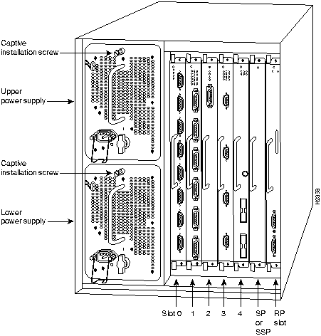
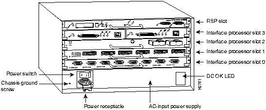
Figure 1 : Cisco 7000 with RP and SP (or SSP) Installed
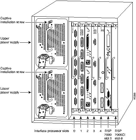
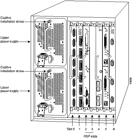
Figure 2 : Cisco 7000 with RSP7000 and RSP7000CI Installed
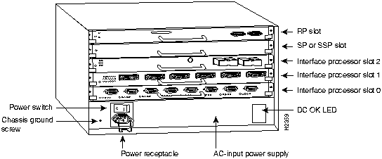
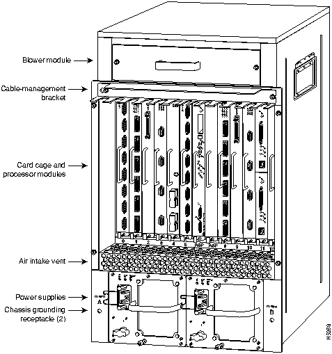
Figure 3 : Cisco 7010 with RP and SP (or SSP) Installed
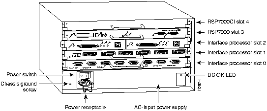
Figure 4 : Cisco 7010 with RSP7000 and RSP7000CI Installed
Removing the RP, SP, SSP, or Interface Processors
Following are detailed steps for removing the RP, SP, SSP, and interface processors. Be sure to use the ejector levers to ensure that the system continues proper operation. Failure to use the ejector levers properly can result in a partial connection between the board connectors and the backplane, which can cause the system to hang and subsequently crash. For detailed descriptions of the OIR function, refer to the Cisco 7000 Hardware Installation and Maintenance, Cisco 7010 Hardware Installation and Maintenance, Cisco 7505 Hardware Installation and Maintenance, Cisco 7507 Hardware Installation and Maintenance, or Cisco 7513 Hardware Installation and Maintenance publications.
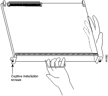
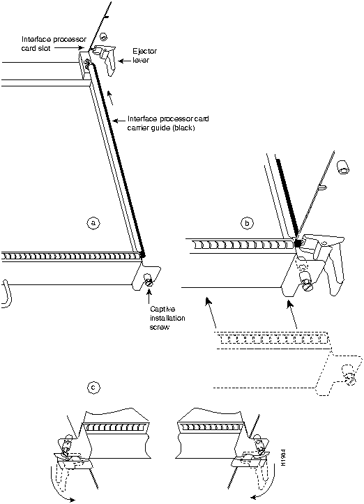
Figure 8 shows proper handling of a processor module for installation in the Cisco 7010 and Cisco 7505 models. The processor slots are oriented horizontally in the Cisco 7010 and Cisco 7505 and vertically in the Cisco 7000, Cisco 7507, and Cisco 7513. For these latter chassis, handle the interface processor in the same manner but rotated 90 degrees clockwise.
Figure 8 : Handling a Processor Module During Installation
Follow these steps and refer to Figure 9 to remove a processor module:
Figure 9 : Ejector Levers and Captive Installation Screws Replacing the RP, SP, SSP, or Interface Processors
Following are the steps for replacing the RP, SP, SSP, or interface processors in the router.
When you remove and replace CxBus interface processors, the system provides status messages across the console screen. The messages are for information only. In the following sample display, you can follow the events logged by the system as an EIP was removed from slot 3, then the system reinitialized the remaining interface processors and marked the EIP that was removed from slot 3 as down. When the EIP was reinserted, the system marked the interfaces as up again.
When you restart the system after replacing the RP, SP or SSP, the console displays the system startup banner, which lists the system software version and all interface types, as follows:
If the system does not display these message or otherwise displays an error message or fails to restart properly, turn off the system power and check the RP, SP, SSP, and interface processor to ensure that all are properly seated. If a second startup attempt fails, contact a service representative. (Refer to the section "Cisco Information Online (CIO)" on page 55.)
Upgrading the System Software ROMs
This section describes procedures for upgrading the system software by replacing the eight read-only memory (ROM) components on the RP and, if necessary, changing the positions of the jumpers on J3 and J4. Currently, most maintenance releases for Software Releases 9.17 and 9.21 are distributed on floppy disk instead of on replacement ROMs (as is done for earlier releases). However, you will need this procedure if ROM replacement is required for a future upgrade or if you want to change the default system boot ROMs in your router.
Cisco 7000 series routers can also netboot system software images, or netboot as part of a fault-tolerant strategy if attempts to boot a Flash or ROM image fails. Refer to the appropriate software configuration documentation for details.
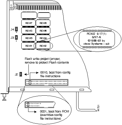
For the RP, the software resides on a set of eight ROMs. The ROMs are labeled with a number that corresponds to the ROM socket in which it should be installed. The sockets have labels too, although obscure, on the silk-screen portion of the RP board. Each ROM has a notch cut on one end to indicate proper orientation. Position new ROMs with the notches in the same position as the notches silkscreened onto the ROM socket. Do not rely on the orientation of the ROM labels to indicate the correct position on the board. Figure 10 shows the ROM numbers of each socket and the location of each on the RP.
Figure 10 : System Software ROMs, Hardware Configuration Register, and Jumpers J2, J3, and J4
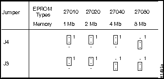
The jumpers on J3 and J4 (see Figure 10) correspond to the size (capacity) of the eight system software ROMs. Figure 10 shows the orientation of J3 and J4 on the RP when set for 2 MB. If you replace the system software ROMs with new ROMs of a different size (larger or smaller than the ROMs you remove), you will also need to change the jumper settings on J3 or J4.
The initial release of System Software 9.17 and all subsequent maintenance releases up to 9.17(6.3) were distributed on 2-MB ROMs. Maintenance release 9.17(7) and subsequent maintenance releases to 9.17, and all releases of Release 9.21, reside on 4-MB ROMs. Cisco IOS Release 10.0 or later resides on 4-MB ROMs. Figure 11 shows the settings for various ROM sizes.
For example, if you are installing a new image that resides on 4-MB ROMs, you will need to move the jumper on J3 from the upper two posts to the lower two posts. This action is not required if you upgrade by downloading a new software image into Flash memory; it is necessary only when you physically replace the ROMs.
Figure 11 : Jumper Settings for Software ROM Sizes
Follow these steps to upgrade the ROMs in the RP:
When you restart the system after replacing the system software ROMs, the system console should display the startup system banner similar to the following example, and the software version should indicate that the router booted from the new ROMs that you just installed.
Verify the installation with the following steps:
This completes the installation verification.
Changing the Boot Field Jumper
The hardware configuration register is a 50-pin jumper block near the front of the RP. (See Figure 10.) The lowest four bits (bits 0 through 3, shown at the far left of the hardware configuration register in Figure 10) form the boot field. The jumper settings of the four boot field bits form a binary value that defines the boot source for the system. This procedure addresses only the settings for booting from ROM and for booting from the instructions in the configuration file. The section "Manually Booting from Flash" on page 24 describes the steps for starting up in the ROM monitor and manually booting from Flash.
This section describes the hardware configuration register boot field jumper settings required for each boot method. For a complete description of the configuration register, refer to the following hardware publications: Route Processor (RP) Installation and Configuration (Document Number 78-1057-xx), Cisco 7000 Hardware Installation and Maintenance, or Cisco 7010 Hardware Installation and Maintenance.
Figure 10 shows the four boot field bits in the hardware configuration register, which are used in systems running software releases other than Cisco IOS Release 10.0 or later.
Removing the jumper completely from the boot field sets the boot field value to 0, which causes the router to start up in the ROM monitor mode. From the ROM monitor, you must manually boot the router with the b (boot) command. (Refer to "Manually Booting from Flash" on page 24.)
A jumper on bit 0 sets the boot field value to 1 (the factory default), which directs the system to boot from the software ROMs. This setting overrides all boot instructions in the system configuration file.
Moving the jumper to any of the other 3 boot field bits directs the system to use the boot instructions in the configuration file. (The system also uses the boot field value to form a filename that it uses for netbooting if it does not find boot instructions in the configuration file; refer to the aforementioned hardware publications for a complete description.)
The factory default boot field setting is 1 (a jumper is on bit 0). However, if you have downloaded and stored a newer system image in Flash memory, you would have had to move the jumper to one of the other three boot field bits, 1-3. To set the system to boot from ROM always and ignore all boot instructions in the system configuration file, place the jumper on bit 0. If you choose this setting, however, you will have to change the jumper before the system can boot from a new image stored in Flash memory, or netboot from a remote router or server.
A more practical and fault-tolerant approach is to set the jumper to any of the other three bits and provide boot instructions in the system configuration file, which you can edit and reconfigure from the system console. Setting boot instructions in the configuration file allows you to define more than one boot source, which directs the system to alternate sources in case the primary boot source fails or is not available. List boot source instructions in the same order that you wish the system to execute them. Use the following commands to direct the system to a boot image:
The following example shows a fault-tolerant boot sequence, which will first attempt to boot from the Flash file g7-103.9. If it cannot boot from this file, it attempts to netboot from a server at the IP address 1.1.1.101. If it cannot netboot, it will boot from ROM. This example assumes that the hardware configuration register boot field (bits 0 through 3) is set to a value of 0x0002 or greater.
The following example shows the same fault-tolerant boot sequence, but in this example the software configuration register is set to boot the router from the Flash file g7-103.9 at the next reboot of the router using the command config-register value (where the value is 0x002):
The following example session instructs the system to boot from the image in ROM, saves the new configuration by writing it to NVRAM, then issues a reload command to execute a soft boot to reload the new software according to the new configuration instructions:
Setting the Flash Write-Protect Jumper
On the RP, jumper J2 provides Flash write protection. A jumper is installed on J2, which is the factory default and allows writing (copying) to Flash memory. To protect the contents of Flash (which prevents writing to it), remove the jumper from J2; however, you must replace the jumper on J2 before you can download or copy any new files or system images to Flash memory.
Figure 10 shows the location of J2, which is just behind and to the left of the configuration register when viewing the RP in the orientation shown.
Microcode is board-specific firmware that resides on ROM on the SP, SSP and on each interface processor. As new software and hardware features are introduced, the microcode may be updated and maintenance versions are released in order to implement new features, improve performance, or fix bugs found in earlier versions. Effective with Cisco IOS Release 10.0, microcode images for all interface processors are bundled with system software upgrades and load automatically with the new system image.
Although in most cases the newer images loaded from Flash will override the default ROM images, some exceptions require ROM replacement to ensure proper startup and operation. Currently, SP Microcode Version 1.4 is the only microcode maintenance release for which ROM replacement is required; all previous microcode maintenance releases for the SP, SSP, and interface processors can be loaded from Flash memory or as part of a bundled system image and are not available on replacement ROMs.
Use the following instructions to replace the microcode ROM on the SP, SSP, or any interface processor. The replacement procedures are the same for each board with the exception of the FSIP, which uses a PLCC-type package for the microcode.
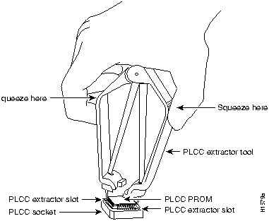
You must use a PLCC extractor to remove the FSIP microcode component. (See Figure 12.) You cannot use a small flat-blade screwdriver to pry it out of the socket as with the older type of ICs. A PLCC IC does not have legs or pins that plug into the socket; instead, the contacts are on the sides of the IC and along the inner sides of the socket. When the IC is seated in the socket, the top of the IC is flush with the top of the socket.
Forcing a small screwdriver or other tool between the IC and the sides of the socket to pry out the IC will damage the component or the socket or both, and you will have to replace them. Figure 13 shows the location of the microcode ROM on each processor module.
Figure 12 : Removing a Microcode Component from a PLCC-Type Package
Following are the steps for replacing the microcode on the SP, SSP, and any interface processor.
![]()
![]()
![]()
C:\> a:install
********************** 7K1000390Z.DOC **********************************
PRODUCT NO. SW-G7-10.3.9=
System Software Image 7K91770Z, GS7-K Version 10.3(9)
Compressed size = 1610960 bytes; Checksum=0xa0df
Copyright (c) 1995 Cisco Systems, Inc.
File 7K10390Z supports all software capabilities for the Cisco 7000.
To install this software in a PCDOS environment enter:
A:install (or use the appropriate drive letter)
To install this software in a UNIX environment enter:
#mount -rt pcfs /dev/fd0 /pcfs
#/pcfs/install.unx (where the user has root privileges)
To install this software onto a router, follow the procedures in
the accompanying publication, "Upgrading System Software and
Microcode in the Cisco 7000."
**********************************************************************
Installation for 7K10390Z complete!
C:\> cd \tftpboot
C:\> dir 7K10390Z.*
![]()
hostname#
mkdir /pcfs
hostname#
mount -t pcfs /dev/fd0 /pcfs
hostname#
mount -rt pcfs /dev/fd0 /pcfs
hostname#
/pcfs/install.unx
********************** 7K10390Z.DOC **********************************
PRODUCT NO. SW-G7-10.3.9=
System Software Image 7K10390Z, GS7-K Version 10.3(9)
Compressed size = 1610960 bytes; Checksum=0xa0df
Copyright (c) 1995 Cisco Systems, Inc.
File 7K100390Z supports all software capabilities for the Cisco 7000.
To install this software in a PCDOS environment enter:
A:install (or use the appropriate drive letter)
To install this software in a UNIX environment enter:
#mount -rt pcfs /dev/fd0 /pcfs
#/pcfs/install.unx (where the user has root privileges)
To install this software onto a router, follow the procedures in the
accompanying publication, "Upgrading Software and Microcode in

Cisco 7000 Family Routers."
**********************************************************************
Installation for 7k10390Z complete!
hostname#
cd /tftpboot
hostname#
ls -l 7k100390z*
Router#
ping
ip-address
[timed out]
[failed]
C:\> ifconfig drivers\drivername show
C:\> ipconfig ftp_3c\ipcust.sys show
hostname# netstat -a | grep tftp
# tftp dgram udp wait root /user/etc/in.tftpd

in.tftpd -s /tftpboot
hostname#
ps -ax | grep -v grep | grep inetd
119 ? S 0:05 inetd
hostname#
kill -HUP 119
hostname#
netstat -a | grep tftp
udp 0 0 *.tftp *.*
hostname#
mkdir /tftpboot
hostname#
chmod 777 /tftpboot
C:> MKDIR \TFTPBOOT
Router# show flash all
4096K bytes of flash memory on embedded flash (in RP1).
   ROM     socket   code    bytes     name
     0      U63     012A   0x40000 AMD 28F020
     1      U62     012A   0x40000 AMD 28F020
     2      U61     012A   0x40000 AMD 28F020
     (display text omitted)
    11      U27     012A   0x40000 AMD 28F020
    12      U17     012A   0x40000 AMD 28F020
    13      U16     012A   0x40000 AMD 28F020
    14      U15     012A   0x40000 AMD 28F020
    15      U14     012A   0x40000 AMD 28F020
  security jumper(12V) is installed,
  flash memory is programmable.

file     offset     length        name
  0     0x80        3           test3
  1     0x1E72E8    97200       fip1-1
  2     0x13EDE0    1305820     7k91720z
  [1582404/4194304 bytes free]
Router#
Router# copy flash tftp filename
IP address of remote host [255.255.255.255]? 1.1.1.6
Name of file to copy []? 7k10390z <Return>
writing 7k91720z!!!!!!!!!!!!!!!!!!!!!!!!!!!!!!!!!!!!!!!!!!!
Router#
Router# ping 1.1.1.101 <Return>
Type escape sequence to abort.
Sending 5, 100-byte ICMP Echoes to 1.1.1.101, timeout is 2 seconds:
!!!!!
Success rate is 100 percent (5/5), round-trip min/avg/max = 1/15/64 ms
Router#
Router# show flash all
4096K bytes of flash memory on embedded flash (in RP1).
   ROM     socket   code    bytes     name
     0      U63     89BD   0x40000 INTEL 28F020
    (displayed text omitted)
    15      U14     89BD   0x40000 INTEL 28F020
  security jumper(12V) is installed,
  flash memory is programmable.

file     offset     length        name
  0     0x80        1995304     gs7-k.103.9.1
  1     0x1E72E8    97200       fip1-1
  (displayed text omitted)
  7     0x2483A4    55418       sp1-2
  [1731676/4194304 bytes free]
The filename can be lowercase or uppercase; the router will see the name as lowercase.
![]()
Router# copy tftp:new.image slot0:new.image
20575008 bytes available on device slot0, proceed? [confirm]
Address or name of remote host [1.1.1.1]?
Loading new.image from 1.1.1.1 (via Ethernet1/0): !!!!!!!!!!!!!!!!!!!!!!!!!!!!!!
!!!!!!!!!!!!!!!!!!!!!!!!!!!!!!!!!!!!!!!!!!!!!!!!!!!!!!!!!!!!!!!!!!!!!!!!!!!!!!!!
!!!!!!!!!!!!!!!!!!!!!!!!!!!!!!!!!!!!!!!!!!!!!!!!!!!!!!!!!!!!!!!!!!!!!!!!!!!!!!!!
!!!!!!!!!!!!!!!!!!!!!!!!!!!!!!!!!!!!!!!!!!!!!!!!!!!!!!!!!!!!!!!!!!!!!!!!!!!!!!!!
!!!!!!!!!!!!!!!!!!!!!!!!!!!!!!!!!!!!!!!!!!!!!!!!!!!!!!!!!!!!!!!!!!!!!!!!!!!!!!!!
!!!!!!!!!!!!!!!!!!!!!!!!!!!!!!!!!!!!!!!!!!!!!!!!!!!!!!!!!!!!!!!!!!!!!!!!!!!!!!!!
!!!!!!!!!!!!!!!!!!!!!!!!!!!!!!!!!!!!!!!!!!!!!!!!!!!!!!!!!!!!!!!!!!!!!!!!!!!!!!!!
!!!!!!!!!!!!!!!!!!!!!!!!!!!!!!!!!!!!!!!!!!!!!!!!!!!!!!!!!!!!!!!!!!!!!!!!!!!!!!!!
!!!!!!!!!!!!!!!!!!!!!!!!!!!!!!!!!!!!!!!!!!!!!!!!!!!!!!!!!!!!!!!!!!!!!!!!!!!!!!!!
!!!!!!!!!!!!!!!!!!!!!!!!!!!!!!!!!!!!!!!!!!!!!!!!!!!!!!!!!!!!!!!!!!!!!!!!!!!!!!!!
!!!!!!!!!!!!!!!!!!!!!!!!!!!!!!!!!!!!!!!!!!!!!!!!!!!!!!!!!!!!!!!!!!!!!!!!!!!!!!!!
!!!!!!!!!!!!!!!!!!!!!!!!!!!!!!!!!!!!!!!!!!!!!!!!!!!!!!!!!!!!!!!!!!!!!!!!!!!!!!!!
!!!!!!!!!!!!!!!!!!!!!!!!!!!!!!!!!!!!!!!!!!!!!!!!!!!!!!!!!!!!!!!!!!!!!!!!!!!!!!!!
!!!!!!!!!!!!!!!!!!!!!!!!!!!!!!!!!!!!!!!!!!!!!!!!!!!!!!!!!!!!!!!!!!!!!!!!!!!!!!!!
!!!!!!!!!!!!!!!!!!!!!!!!!!!!!!!!!!!!!!!!!!!!!!!!!!!!!!!!!!!!!!!!!!!!!!!!!!!!!!!!
!!!!!!!!!!!!!!!!!!!!!!!!!!!!!!!!!!!!!!!!!!!!!!!!!!!!!!!!!!!!!!!!!!!!!!!!!!!!!!!!
!!!!!!!!!!!!!!!!!!!!!!!!!!!!!!!!!!!!!!!!!!!!!!!!!!!!!!!!!!!!!!!!!!!!!!!!!!!!!!!!
!!!!!!!!!!!!!!!!!!!!!!!!!!!!!!!!!!!!!!!!!!!!!!!!!!!!!!!!!!!!!!!!!!!!!!!!!!!!!!!!
!!!!!!!!!!!!!!!!!!!!!!!!!!!!!!!!!!!!!!!!!!!!!!!!!!!!!!!!!!!
[OK - 7799951/15599616 bytes]
CCCCCCCCCCCCCCCCCCCCCCCCCCCCCCCCCCCCCCCCCCCCCCCCCCCCCCCCCCCCCCCCCCCCCCCCCCCCCCCC
CCCCCCCCCCCCCCCCCCCCCCCCCCCCCCCCCCCCCCCCCCCCCCCCCCCCCCCCCCCCCCCCCCCCCCCCCCCCCCCC
CCCCCCCCCCCCCCCCCCCCCCCCCCCCCCCCCCCCCCCCCCCCCCCCCCCCCCCCCCCCCCCCCCCCCCCCCC
Router#
Error programming flash memory
erase flash before writing? [confirm] <Return>
Router# show flash all
4096K bytes of flash memory on embedded flash (in RP1).
   ROM     socket   code    bytes     name
     0      U63     012A   0x40000 AMD 28F020
     1      U62     012A   0x40000 AMD 28F020
(display text omitted)
  security jumper(12V) is installed,
  flash memory is programmable.

file     offset     length        name
  0     0x80        3           test3
  1     0xC4        1305820     gs7-k.917-2.Z
  2     0x13EDE0    1305820     7k91720z
  [1582404/4194304 bytes free]
Router# show flash
4096K bytes of flash memory on embedded flash (in RP1).

file    offset      length      name
  0     0x80        2060240     gs7-k.103-8
  1     0x2577F0    98162       flip1-2
[1656560/4194304 bytes free]

Router# copy verify
Name of file to verify [flip1-2]? gs7-k.103-8
Verifying via checksum...
vvvvvvvvvvv
Flash verification successful.  Length = 2060240, checksum = 0x0a42
Router#
![]()
Router# pwd
slot0
Router# cd slot0
slot0
Router# cd slot1
Router# pwd
slot1
Router# dir
-#- -length- -----date/time------ name
1   4601977  May 19 1994 09:42:19 myfile1
6   679      May 19 1994 05:43:56 todays--config
7   1        May 19 1994 09:54:53 fun1
Router# delete slot0:fun1
Router# dir
-#- -length- -----date/time------ name
1   4601977  May 19 1994 09:42:19 myfile1
6   679      May 19 1994 05:43:56 todays--config
Router# squeeze slot0:
All deleted files will be removed, proceed? [confirm]
Squeeze operation may take a while, proceed? [confirm]
ebESZ
Router# write terminal (or copy running-config)

Current configuration:
version 10.3
!
hostname Router
!
microcode fip flash fip1-1
microcode sp flash sp1-2
microcode reload
![]()
Router#
configure terminal
Enter configuration commands, one per line.
Edit with DELETE, CTRL/W, and CTRL/U; end with CTRL/Z
Router(config)#
no boot system flash 7k1038z
(Tells system not to boot old filename)
Router(config)#
boot system flash 7k10390z
(Tells system to boot new filename)
Router(config)#
no microcode sp flash sp1-2 (Tells system not to boot SP mcode from Flash)
Router(config)#
no microcode fip flash fip1-1 (Tells system not to boot FIP mcode from Flash)
Router(config)#
^Z
Router#
write memory
(
copy running-config startup-config
)
[ok]
Router#
Router#
reload
[confirm] <Return>
%SYS-5-RELOAD: Reload requested
System Bootstrap, Version 5.3(0.3), SOFTWARE
Copyright (c) 1986-1995 by cisco Systems
RP1 processor with 16384 Kbytes of main memory
F3: 8336+3474931+165004 at 0x1000
![]()
System Bootstrap, Version 5.3(0.3), SOFTWARE
Copyright (c) 1986-1995 by cisco Systems
RP1 processor with 16384 Kbytes of main memory
F3: 8336+3474931+165004 at 0x1000
>
b
flash 7k100390z
F3: 1933984+47288+179884 at 0x1000
Booting clean_syscode from flash memory RRRRRRRRRRRRRRRRRRRRRRRRRRRRRRRRRRRRRRRRRRRRRRRRRRRRRRRRRRRRRRRRRRRRRRRRR
RRRRRRRRRRRRRRRRRRRRRRRRRRRRRRRRRRRRRRRRRRRRRRRRRRRRRRRRRRRRRRRRRRRRRRRRR
RRRRRRRRRRRRRRRRRRRRRRRRRRRRRRRRRRRRRRRRRRRRRRRRRRRRRRRRRRRRRRRRRRRRRRRRR
RRRRRRRRRRRRRRRRRRRRRRRRRRRRRRRRRRRRRRRRRRRRRRRRRRRRRRRRRRRRRRRRRRRRRRRRR
RRRRRRRRRRRRRRRRRRRRRRRRRRR [OK - 1981304/13553764 bytes]
F3: 1933984+47288+179884 at 0x1000
Restricted Rights Legend
Use, duplication, or disclosure by the Government is subject to restrictions
(displayed text omitted)
Press RETURN to get started! <Return>
Router>
![]()
microcode fip rom
no microcode fip rom
Router# show microcode <Return>

Microcode bundled in system

Card      Microcode       Target Hardware  Description
Type      Version         Version
----      ---------       ---------------  ----------------
SP        10.4            11.x             SP version 10.4
SSP       10.4            12.x             SP version 10.4
EIP       10.0             1.x             EIP version 10.0
TRIP      10.1             1.x             TRIP version 10.1
FIP       10.1             2.x             FIP version 10.1
HIP       10.0             1.x             HIP version 10.0
SIP        1.2             1.x             SIP version 1.2
FSIP      10.3             1.x             FSIP version 10.3
MIP       10.1             1.x             MIP version 10.1
AIP       10.1             1.x             AIP version 10.1

(As of Cisco IOS Release 11.1[1], CIP microcode is no longer bundled.)
![]()
![]()
![]()
![]()
Router#
%OIR-6-REMCARD: Card removed from slot 3, interfaces disabled
%LINK-5-CHANGED: Interface TokenRing4/0, changed state to initializing
%LINK-5-CHANGED: Interface Ethernet3/1, changed state to administratively down
%LINK-5-CHANGED: Interface Ethernet3/5, changed state to administratively down
%LINK-5-CHANGED: Interface TokenRing4/0, changed state to up

Router#
%OIR-6-INSCARD: Card inserted in slot 3, interfaces administratively shut down
%LINK-5-CHANGED: Interface TokenRing4/0, changed state to initializing
%LINK-5-CHANGED: Interface Ethernet3/1, changed state to up
%LINK-5-CHANGED: Interface Ethernet3/5, changed state to up
%LINK-5-CHANGED: Interface TokenRing4/0, changed state to up
Restricted Rights Legend
Copyright (c) 1986-1995 by cisco Systems
RP1 processor with 16384 Kbytes of main memory
F3: 8336+3474931+165004 at 0x1000
Restricted Rights Legend
Use, duplication, or disclosure by the Government is
subject to restrictions as set forth in subparagraph
(c) of the Commercial Computer Software - Restricted
Rights clause at FAR sec. 52.227-19 and subparagraph
(c) (1) (ii) of the Rights in Technical Data and Computer
Software clause at DFARS sec. 252.227-7013.
cisco Systems, Inc.
170 West Tasman Drive
San Jose, California 95134-1706
Cisco Internetwork Operating System Software
IOS (tm) GS Software (GS7-K), Version 10.3(8), RELEASE SOFTWARE (fc1)
Copyright (c) 1986-1995 by cisco Systems, Inc.
Compiled Wed 01-Nov-95 13:55 by vatran
Image text-base: 0x00001000, data-base: 0x0061E5B4
RP (68040) processor with 16384K bytes of memory.
G.703/E1 software, Version 1.0.
X.25 software, Version 2.0, NET2, BFE and GOSIP compliant.
Bridging software.
1 EIP controller (2 Ethernet).
2 FSIP controllers (4 Serial).
2 Ethernet/IEEE 802.3 interfaces.
4 Serial network interfaces.
128K bytes of non-volatile configuration memory.
4096K bytes of flash memory sized on embedded flash.
8192K bytes of Flash PCMCIA card at slot 0 (Sector size 128K).
![]()
Restricted Rights Legend
Copyright (c) 1986-1995 by cisco Systems
RP1 processor with 16384 Kbytes of main memory
F3: 8336+3474931+165004 at 0x1000
(displayed text omitted)
cisco Systems, Inc.
170 West Tasman Drive
San Jose, California 95134-1706
Cisco Internetwork Operating System Software
IOS (tm) GS Software (GS7-K), Version 10.3(9), RELEASE SOFTWARE (fc1)
Copyright (c) 1986-1995 by cisco Systems, Inc.
Compiled Wed 01-Nov-95 13:55 by biff
Image text-base: 0x00001000, data-base: 0x0061E5B4
System image file is "gs7-k.103-9", booted via ROM
Router# configure terminal
Enter configuration commands, one per line.
Edit with DELETE, CTRL/W, and CTRL/U; end with CTRL/Z
Router(config)#boot system flash g7-103.9
Router(config)#boot system g7-103.9 1.1.1.101
Router(config)#boot system rom
Router(config)#^z
Router# write memory (copy running-config startup-config)
[ok]
Router#
Router# conf term
Enter configuration commands, one per line.
Edit with DELETE, CTRL/W, and CTRL/U; end with CTRL/Z
Router(config)#config-register 0x002
Router(config)#boot system flash g7-103.9
Router(config)#boot system g7-103.9 1.1.1.101
Router(config)#boot system rom
Router(config)#^z
Router# write memory (copy running-config startup-config)
[ok]
Router#
Router> enable
Password: (not displayed)

Router# configure terminal
Enter configuration commands, one per line.
Edit with DELETE, CTRL/W, and CTRL/U; end with CTRL/Z
Router(config)#boot system rom
Router(config)#^z

Router# write memory (copy running-config startup-config)
[ok]
Router#

Router# reload
[confirm]

%SYS-5-RELOAD: Reload requested
Cisco Internetwork Operating System Software
IOS (tm) GS Software (GS7-K), Version 10.3(9), RELEASE SOFTWARE (fc1)
Copyright (c) 1986-1995 by cisco Systems, Inc.
Compiled Wed 01-Nov-95 13:55 by biff

Booting from g7-103.9 from rom
RRRRRRRRRRRRRRRRRRRRRRRRRRRRRRRRRRRRRRRR
(displayed text omitted
RRRRRRRRRRRRRRRRRRRRRRRRRRR [OK - 1582404/4194304 bytes]
F1: 1871414+45476+167028 at 0x1000

          Restricted Rights Legend

Use, duplication, or disclosure by the Government is
(displayed text omitted)
![]()