|
|
Silicon Switch Processor (SSP) Installation and Configuration
Product Numbers: SSP=, UPG-SSP, SSP-2MB=, UPG-SSP-2MB, and UPG-SSP-.5to2MB
This publication contains instructions for installing the Silicon Switch Processor (SSP) and upgrading the software in Cisco 7000 series routers: the Cisco 7000 and the Cisco 7010.
The sections of this publication include the following:
Following are the SSP-related product numbers:
The SSP is the high-performance silicon switch for Cisco 7000 series routers. There are two hardware versions of the SSP: one with 512 KB of packet memory and another with 2 MB of packet memory, for installations requiring increased memory capacity.
For specific software requirements for each SSP configuration, refer to the section "Software Upgrade Prerequisites" on page 8.
The SSP and the Route Processor (RP), which contains the system processor, provide distributed processing and control for the interface processors. Network interfaces reside on the modular interface processors that provide a direct connection between the high-speed, 533-Mbps Cisco Extended Bus (CxBus) and the external networks. The SSP, shown in Figure 1, communicates with and controls the interface processors on the high-speed CxBus. The SSP determines the destination of a packet and switches the packet, based on that decision. The SSP is always installed in the backplane SP slot adjacent to the RP. (See Figure 2 and Figure 3.) A few seconds after bootup, the LED labeled Enabled goes on to indicate that the SSP is enabled for operation. One SSP (or SP) is required in each Cisco 7000 series router.
Figure 1 Silicon Switch Processor (SSP)

The Cisco 7000 Series comprises the five-slot Cisco 7010 and the seven-slot Cisco 7000. Both models use the same Route Processor (RP), Silicon Switch Processor (SSP), and interface processors. The Cisco 7000 provides five interface slots and offers a second modular power supply for redundant power. The Cisco 7010 provides three interface slots, and offers the same performance as the Cisco 7000.
Figure 2 shows the interface processor end of the Cisco 7000 model, which provides access to the seven processor slots and the removable power supplies. When facing the interface processor end of the chassis, the RP and SP slot are on the far right. The five interface processor slots are numbered 0 to 4 from left to right. In both models, interface processor slots support any combination of network interface types: Ethernet, Token Ring, fiber distributed data interface (FDDI), serial, and high-speed serial interface (HSSI). The RP, SP, and interface processors are keyed with guides on the backplane to prevent them from being fully inserted in the wrong slot. The SSP (or SP), RP, and interface processors slide into slots in the rear of the chassis and connect directly to the backplane. The backplane slots are keyed so that the SSP or SP, RP, and interface processors are installable only in the slots designated for them. The SSP inserts into the slot formerly reserved for the SP.
Figure 2 Cisco 7000---Interface Processor End
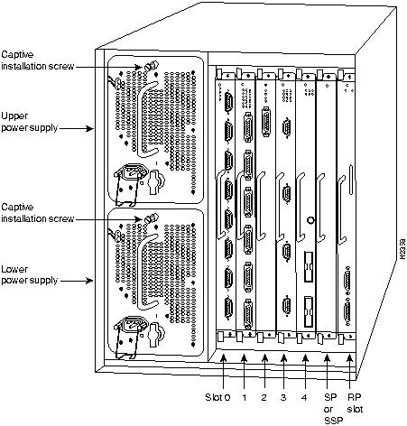
Figure 3 shows the interface processor end of the Cisco 7010 model, which provides access to the five processor slots, the AC input receptacle, the power switch, and a power status indicator. When facing the interface processor end of the chassis, the RP and SP slots are at the top. The three interface processor slots are numbered from the bottom up beginning with slot 0 (the bottom slot) through slot 2 (the center slot).
Figure 3 Cisco 7010---Interface Processor End
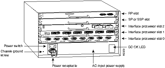
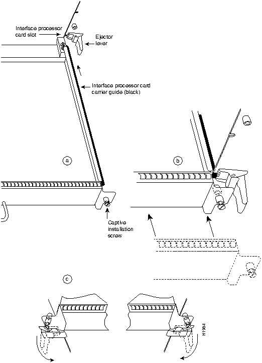
Figure 4 shows the ejector levers and captive installation screws on a typical interface processor. To remove an interface processor, loosen the captive screws and pull the ejector levers to the sides; then pull the module out using the handle. To insert an interface processor, reverse the process, making sure to firmly seat the interface processor in its connectors on the backplane. For detailed directions, follow the procedures in "Removing the SP or SSP" and "Replacing an SSP in the Chassis."
![]()
The captive installation screws on the ends (see Figure 4) of each faceplate, when tightened, provide electromagnetic interference (EMI) shielding and also help ensure proper seating in the backplane. After using the ejector levers to install an SSP, tighten the captive installation screws to prevent the SSP from becoming partially dislodged from the backplane. These screws must be tightened to meet EMI specifications.
Figure 4 Ejector Levers and Captive Installation Screws---Horizontal Orientation Shown
Before you begin the installation of the SSP, review the tools and parts required, and the safety and ESD-prevention guidelines in this section.
You need some or all of the following tools and parts to perform the following procedures. Before you begin, read the entire procedure to determine which tools you need for the installation or upgrade you will perform.
Follow these basic guidelines when working with any electrical equipment:
In addition, use the guidelines that follow when working with any equipment that is connected to telephone wiring or other network cabling.
Electrostatic discharge (ESD) damage, which can occur when electronic cards or components are improperly handled, results in complete or intermittent failures. The SSP comprises a printed circuit board that is fixed in a metal carrier. Electromagnetic interference (EMI) shielding, connectors, and a handle are integral components of the carrier. Although the metal carrier helps to protect the board from ESD, use a preventive antistatic strap whenever handling the SSP. Handle the carriers by the handles and the carrier edges only; never touch the boards or connector pins.
![]()
Following are guidelines for preventing ESD damage:
![]()
Following are minimum system requirements for the SSP hardware types:
To successfully upgrade the system software and microcode, you must have the following:
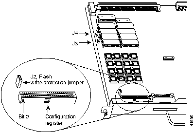
Figure 5 RP Flash Write-Protection Jumper
This section describes the general steps required to upgrade your system software on a Cisco 7000 series router. The sections that follow describe these steps in detail.
(text deleted)
Verifying via checksum...
Flash verification successful. Length = 1906676, checksum = 0x12AD
You must be able to issue commands to the router on which you are upgrading the software. For example, this publication tells you to issue a command to download the image from the TFTP server to the router.
If you have a console port connection to the router, you need not invoke a Telnet session. If you do not have a console port connection to the router, you must establish a Telnet session with the router so that you can issue the router commands.
You can set up a Telnet session from a Sun workstation or from a PC.
This section presents the following topics:
If you do not already have the current system software image and backup configuration file on your TFTP server, make sure you back up these files before copying the new system software image to Flash memory on your router.
To display the total amount of Flash memory present, its location, any files that currently exist in Flash memory and their size, and the amount of Flash memory remaining, use the show flash command. The following (typical) output displays:
Router> show flash
4096K bytes of flash memory sized on embedded flash.
File  name/status
 0  gs7-k.103-1
 1  micro/ssp10-5
 [246400/4194304 bytes free/total]
Use the file name near the bottom of the show flash command screen output (in this case gs7k.101) when you back up the image.
Copy the image from Flash memory to a TFTP server using the copy flash tftp command:
Router# copy flash tftp
The router prompts you for the IP address of the TFTP server and the name of the image file you are copying to the server.
A sample of the output for this command using IP address 1.1.1.11 and filename gs7-k.103-1 follows:
IP address of remote host [255.255.255.255]? 1.1.1.11
Name of file to copy []? gs7-k.103-1
writing gs7-k.103-1 !!!!!!!!!!!!!!!!!!!!!!!!!!!!!!!!!!!!!!!!!!!
Router#
Use the image you backed up to the TFTP server if the upgrade image is damaged.
To make a backup copy of your configuration file, enter the write network command. You will be prompted for the remote host IP address and the name of the configuration file, as follows:
Router# write net
Remote host []? 1.1.1.11
Name of configuration file to write [router-confg]? cisco1-config
Write file cisco1-config on host 1.1.1.11? [confirm]
###
Writing cisco1-config !! [OK]
Use the backup configuration file if the image on the router is inadvertently overwritten.
You can download a new system image to Flash memory by copying the image using TFTP. When the new version of the system image is available in Flash memory, you can boot the router either automatically or manually from Flash memory.
Follow these steps to copy a new system image version from the TFTP server to Flash memory.
Router# copy tftp flash
File  name/status
 0  gs7-k.100-1
 [1103564/4194304 bytes free/total]
Address or name of remote host [1.1.1.11]? 1.1.1.11
Source file name? [gs7-k.100-1] gs7-k.103-4
Destination file name? [gs7-k.103-1] <Return>
Accessing file 'gs7-k.103-4' on 1.1.1.11... found !
903500 bytes available for writing without erasure.
Erase flash device before writing? [confirm] y
Flash contains files.  Are you sure? [no]: y
Copy 'gs7-k.103-4' from server
  as 'gs7-k.103-4' into Flash WITH erase? [yes/no] y
Erasing... eeeeeeeeeeeeeeeeeeeeeeeeeeeeeeeeeeeeeeeeeeeeeeeeeeeeeeeeeeeeeeee
Loading gs7-k.103-4 from 1.1.1.11 (via Ethernet1/0): !
[OK - 3320245/4194176 bytes]
Verifying via checksum...
Flash verification successful.  Length = 3320245, checksum = 0xA83D
When configuring the system to boot from Flash memory, first configure no boot system and then configure boot system flash filename. Configuring no boot system clears all the boot system commands, which are stored in the order that they are entered.
From the enable-mode prompt (#) on the router, enter the EXEC command write terminal to see if the boot system flash command line in the configuration file has the filename argument, as follows:
Router>         enable
Password:
Router# write term
Current configuration:
!
(text deleted)
boot system flash
(text deleted)
If the boot system flash command does not appear in the system configuration, you can configure the router to automatically boot from the image in Flash memory by following this procedure:
The following example shows the sequence of steps for replacing a Cisco IOS 10.0 image with a Release 10.3(4) image. Substitute the different image names.
Router# configure terminal
Enter configuration commands, one per line.  End with CNTL/Z.
Router(config)# no boot system flash 7k10020z (Removes old filename)
Router(config)# boot system flash gs7-k.103.4 (Tells system to boot new filename)
Router(config)# ^Z
Router# write memory
[ok]
Router#
Reboot the router with the reload command.
If the image fails to load properly into Flash memory, the following error message appears:
Error programming flash memory
If you try loading the image into Flash memory three or more times and repeatedly see the previous message, contact technical support.
In an attempt to recover from the error, you also can erase the Flash memory and try to download the file again. To erase the Flash memory, issue the copy tftp flash command and press Return or Y at the following prompt:
erase flash before writing? [confirm] <Return>
Having successfully copied an image into Flash memory, you can display the image name by issuing the show flash command.
After you install the SSP, you must enable Silicon Switch Engine (SSE) switching with the ip route-cache sse command. The ip route-cache sse command is comparable to the ip route-cache cbus command used to enable autonomous switching in the Switch Processor (SP). Enter the ip route-cache sse command from the Configuration mode, as follows:
Router# conf term
Enter configuration commands, one per line.  End with CNTL/Z.
Router(config)# int ether 1/0
Router(config-if)# ip route-cache sse
Router(config-if)# ^Z
Router#
For additional information on SSE switching, refer to the appropriate router software publication.
Use the show commands for determining the successful installation and operation of the SSP.
The show sse summary command displays the following summary of the processor statistics:
Router# show sse sum
SSE utilization statistics
               Program words  Rewrite bytes  Internal nodes  Depth  Rebuilds
Overhead                 500              5               4
IP                      6607            133            6550     15         1
IPX                        0              0               0      0         2
SRB                        0              0               0      0         2
CLNP                       0              0               0      0     44082
IP access lists            0              0               0
Total used              7107            138            6554
Total free             58429         262006
Total available        65536         262144
Internals
  15001487 internal nodes allocated, 14994933 freed
  SSE manager process enabled, microcode enabled and running, 0 hangs
Router#
The show ip cache command displays the following:
Router# show ip cache
IP routing cache version 0, 5827 entries, 819880 bytes
Minimum invalidation interval 2 seconds, maximum interval 5 seconds,
   quiet interval 3 seconds, threshold 0 requests
Invalidation rate 0 in last second, 0 in last 3 seconds
Prefix/Length       Age       Interface       MAC Header
6.0.0.0/8           2:02:35   Hssi1/0         0F000800
13.0.0.0/8          1:23:57   Fddi0/0         00000C0BA9DA00000C0DDF9CAAAA0300
                                              00000800
15.0.0.0/8          0:00:44   Fddi0/0         00000C0BA9DA00000C0DDF9CAAAA0300
                                              00000800
16.0.0.0/8          0:20:15   Fddi0/0         00000C03510300000C0DDF9CAAAA0300
                                              00000800
17.0.0.0/8          0:19:14   Fddi0/0         00000C0BA9DA00000C0DDF9CAAAA0300
                                              00000800
The show ip interface brief command displays the interfaces that are enabled.
To display statistics, including the controller type, MAC addresses, and microcode versions, enter the show controllers cbus command, as follows:
Router# show cont cbus
Switch Processor 5, hardware version 12.0, microcode version 10.8 Altera 4
  Microcode loaded from system
  2048 Kbytes of main memory, 128 Kbytes cache memory
  4 256 byte buffers, 4 1024 byte buffers, 438 4496 byte buffers
  Restarts: 0 line down, 0 hung output, 0 controller error
 FIP 0, hardware version 2.4, microcode version 10.2
  Microcode loaded from system
  Interface 0 - Fddi 0/0, address 0000.0c04.b038 (bia 0000.0c04.b038)
    62 buffer RX queue threshold, 47 buffer TX queue limit, buffer size 4496
    ift 0006, rql 32, tq 0000 01C0, tql 47
The SSP does not support online insertion and removal (OIR), so you must turn all system power OFF before removing the SSP from the chassis.
Always use the ejector levers to remove or install the SSP. The ejectors help to ensure that backplane connectors on the card are fully seated in, or fully ejected from, the backplane (refer to the description in the section "Cisco 7000 Series Overview"). Failure to use the ejector levers could result in a partial backplane connection and subsequent system crash.
Follow these steps to remove and replace the SSP:
Figure 6 Handling the SSP During Installation
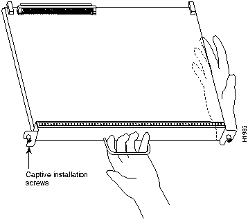
Ensure that all power supplies are turned OFF (O) before installing the SSP in the chassis. The SSP, RP, and interface processors are all keyed for installation only in the correct slot. (Refer to "SSP Description.") Install the SSP in the SP slot (see Figure 2 and Figure 3), as follows:
![]()
![]()
![]()
Follow these steps to verify that the SSP is installed and functioning properly:
Cisco Internetwork Operating System Software
IOS (tm) GS Software (GS7), Version 10.3(3), RELEASE SOFTWARE
Copyright (c) 1986-1995 by cisco Systems, Inc.
Compiled Wed 10-May-95 03:33
(displayed text omitted from example)
After verifying all of the conditions in the previous steps, your installation is complete.
An error condition exists if any of the enabled LEDs fail to come on after initialization or if the boot error or CPU halt LEDs come on and remain on. If this happens, proceed to "Troubleshooting the Installation" to try to isolate the problem.
This section contains procedures to follow if the system does not restart and boot as expected. Review the descriptions that follow, so you can anticipate the expected system startup sequence. Then restart the system and try to isolate the problem by observing the LEDs as the system attempts to boot the software and initialize the SSP and each interface processor.
The troubleshooting procedures in this section assume that your system was operating correctly up until the time you install or replace the SSP and that any problems are a result of the newly installed or upgraded SSP.
If the troubleshooting procedures indicate a problem with the power subsystem or one of the interface processor cards, refer to the Cisco 7000 Hardware Installation and Maintenance or Cisco 7010 Hardware Installation and Maintenance publications for complete system startup troubleshooting procedures.
Following are functional descriptions of the LEDs on the power supplies and processor modules, and the behavior you should observe at system startup.
Cisco 7000 series models have a system power LED that should go on and stay on when the system power is turned on. If the LED does not go on or stay on, there is most likely a problem with the input power or one of the internal DC lines.
On the Cisco 7010, the system power LED is located on the lower right of the interface processor end of the chassis and is labeled DC OK. (See Figure 3.) The rocker-type power switch turns the power supply on and starts the system.
On the Cisco 7000, which operates with either one or two power supplies, the system power LEDs are labeled and located on the individual power supplies. Each supply contains AC (or DC) power and DC fail LEDs and a power switch. (See Figure 7.) When you turn on a power supply, the green power LED should go on. The yellow DC fail LED should remain off. The power LED will not go on if the power supply switch is not fully in the ON (|) position, or if the power supply is not properly seated in the bay.
In both models, the power LED will not go on or will go off if the power supply reaches an outoftolerance temperature or voltage condition. The power supply is unlikely to shut down during startup because of an overtemperature condition; the power supply can, however, shut down if the power supply detects an over- or under-voltage condition during startup.
For descriptions of environmental monitoring functions, refer to the Cisco 7000 Hardware Installation and Maintenance or the Cisco 7010 Hardware Installation and Maintenance publications.
Figure 7 Cisco 7000 Power Supply LEDs
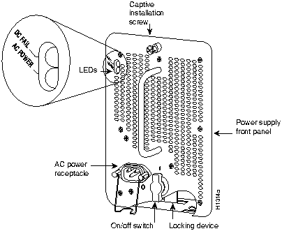
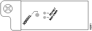
Figure 8 shows the three LEDs on the RP faceplate. These LEDs indicate the system and RP status. When the router is turned on or restarted, the boot error LED goes on for one or two seconds, then goes off. The CPU halt LED, which goes on only if the system detects a processor hardware failure, remains off. If the boot error LED remains on for more than five seconds, the router is unable to boot and you must restart the router. A successful boot is indicated when the boot error LED goes off; however, this does not necessarily mean that the system has reached normal operation. During normal operation, the CPU halt and boot error LEDs are off, and the normal LED is on.
Figure 8 RP LEDs (Horizontal Cisco 7010 Orientation Shown)
The SSP and each interface processor contain an enabled LED. The enabled LED goes on to indicate that the SSP or interface processor is operational and powered up. All enabled LEDs (on the SSP and interface processors) go on when the boot sequence is complete. If the enabled LEDs do not come on, one of the following errors is indicated:
By checking the state of the LEDs, you can determine when and where the system failed in the startup sequence. The Cisco 7000 features redundant LEDs on the front of the chassis for the RP normal system status LED and the power LEDs on the power supplies. However, because the states reported by these LEDs are also indicated at the interface processor end of the chassis, these LEDs are ignored in the following procedure. Because you turn the system power on with the power supply switches, the startup behavior is easiest to observe from the rear of the chassis. Use the following descriptions of the normal startup sequence to isolate the problem, then use the troubleshooting procedures wherever the system fails to operate as expected. If you are able to isolate the problem to a faulty hardware component, or if you are unable to successfully restart the system, refer to the end of this document for instructions for contacting a customer service representative.
The pause in the banner display occurs after the copyright line, and before the system displays the list of installed hardware, as shown in the following display:
%SYS-5-RELOAD: Reload requested
System Bootstrap, Version 4.6(7.3)
Copyright (c) 1986-1995 by cisco Systems, Inc.
(System initializes memory at this point in the display)
RP1 processor with...
When you restart up the system, the system power LEDs (DC OK on the Cisco 7010, and AC power on the Cisco 7000) should indicate the following:
Cisco Internetwork Operating System Software
Cisco IOS Software (GS7), Version 10.3(4), RELEASE SOFTWARE

(or 10.0(11) or later, or 10.2[7] or later, or 11.0(1) or later)
Copyright (c) 1986-1995 by cisco Systems, Inc.
Compiled Mon 10-Apr-95 03:33
If the system still fails to start up or operate properly after you perform these troubleshooting procedures, or if you isolate the cause of the problem to a failed component, contact a customer service representative for further assistance.
This completes the SSP installation and replacement procedure. For complete command descriptions and examples, refer to the appropriate software publications.
Cisco Connection Online (CCO) is Cisco Systems' primary, real-time support channel. Maintenance customers and partners can self-register on CCO to obtain additional content and services.
Available 24 hours a day, 7 days a week, CCO provides a wealth of standard and value-added services to Cisco's customers and business partners. CCO services include product information, software updates, release notes, technical tips, the Bug Navigator, configuration notes, brochures, descriptions of service offerings, and download access to public and authorized files.
CCO serves a wide variety of users through two interfaces that are updated and enhanced simultaneously---a character-based version and a multimedia version that resides on the World Wide Web (WWW). The character-based CCO (called "CCO Classic") supports Zmodem, Kermit, Xmodem, FTP, Internet e-mail, and fax download options, and is excellent for quick access to information over lower bandwidths. The WWW version of CCO provides richly formatted documents with photographs, figures, graphics, and video, as well as hyperlinks to related information.
You can access CCO in the following ways:
http://www.cisco.com
cio.cisco.com
(198.92.32.130)
For a copy of CCO's Frequently Asked Questions (FAQ), contact
ciohelp@cisco.com.
For additional information, contact
cioteam@cisco.com.
If you are a network administrator and need personal technical assistance with a Cisco product that is under warranty or covered by a maintenance contract, contact Cisco's Technical Assistance Center (TAC) at 800 553-2447, 408 526-7209, or
tac@cisco.com.
To obtain general information about Cisco Systems, Cisco products, or upgrades, contact 800 553-6387, 408 526-7208, or
csrep@cisco.com.

|
|
Copyright 1988-1995 © Cisco Systems Inc.