|
|
SA-Comp/1 and SA-Comp/4 Data Compression Service Adapter Installation and Configuration
Product Numbers: SA-Comp/1(=), SA-Comp/4(=)
This configuration note describes the installation and configuration of the data compression service adapters (referred to throughout this publication collectively as CSA), which are used in the Cisco 7200 series routers and on the second-generation Versatile Interface Processor (VIP2) in all Cisco 7500 series routers, and in Cisco 7000 series routers using the 7000 Series Route Switch Processor (RSP7000) and 7000 Series Chassis Interface (RSP7000CI). (The specific VIP2 model required by the CSA is VIP2-40.)
For complete descriptions of interface subcommands and the configuration options available for interfaces, and which support CSA functionality, refer to the appropriate Cisco Internetwork Operating System (Cisco IOS) configuration publication listed in the section "If You Need More Information."
The section "Cisco Connection Online," on page 40, includes general reference information.
The Cisco Internetwork Operating System (Cisco IOS) software running your router contains extensive features and functionality. The effective use of many of many of these features is easier if you have more information at hand. For additional information on configuring the Cisco 7000 family routers and VIP2, or the Cisco 7200 series, the following documentation resources are available:
The basic function of data compression is to reduce the size of a data frame to be transmitted over a network link. Reducing the size of the frame reduces the time required to transmit the frame across the network. Data compression works by providing a coding scheme at each end of a transmission link that allows characters to be removed from the frames of data at the sending side of the link and then replaced correctly at the receiving side. Because the condensed frames take up less bandwidth, greater numbers of them can be transmitted per unit of time.
Data compression schemes used in internetworking devices are referred to as lossless compression algorithms. These schemes reproduce the original bit streams exactly, with no degradation or loss, a feature required by routers and other devices to transport data across the network. The two most commonly used compression algorithms on internetworking devices are the Stacker compression and Novell predictor data compression algorithms.
Stacker compression was developed by STAC Electronics and is based on the Lempel-Ziv compression algorithm. The Stacker algorithm uses an encoded dictionary that replaces a continuous stream of characters with codes. The symbols represented by the codes are stored in memory in a dictionary-style list. Because the relationship between a code and the original symbol varies as the data varies, this approach is more responsive to the variations in the data. This flexibility is particularly important for LAN data, because many different applications can be transmitting over the WAN at any one time. In addition, as the data varies, the dictionary changes to accommodate and adapt to the varying needs of the traffic.
The predictor compression algorithm tries to predict the next sequence of characters in a data stream by using an index to look up a sequence in the compression dictionary. It then examines the next sequence in the data stream to see if it matches. If it does, that sequence replaces the looked-up sequence in the dictionary. If there is no match, the algorithm locates the next character sequence in the index and the process begins again. The index updates itself by hashing a few of the most recent character sequences from the input stream.
Cisco internetworking devices use the Stacker and predictor data compression algorithms. The CSA only supports the Stacker algorithm.
Compression Service Adapter Installation Prerequisites
This section provides the software and hardware requirements, a list of parts and tools you will need to perform the installation, and safety and ESD-prevention guidelines to help you avoid injury and damage to the equipment.
Software and Hardware Requirements
Following are specific hardware and software prerequisites to ensure proper operation of the CSA:
You need the following tools and parts to install a compression service adapter. If you need additional equipment, contact a service representative for ordering information.
Following are safety guidelines that you should follow when working with any equipment that connects to electrical power or telephone wiring.
Electrical Equipment Guidelines
Follow these basic guidelines when working with any electrical equipment:
Use the following guidelines when working with any equipment that is connected to telephone wiring or to other network cabling:
Preventing Electrostatic Discharge Damage
Electrostatic discharge (ESD) damage, which can occur when electronic cards or components are improperly handled, results in complete or intermittent failures. A processor module comprises a printed circuit board that is fixed in a metal carrier. Electromagnetic interference (EMI) shielding, connectors, and a handle are integral components of the carrier. Although the metal carrier helps to protect the board from ESD, use a preventive antistatic strap whenever handling a processor module.
Following are guidelines for preventing ESD damage:
![]()
What Is the Data Compression Service Adapter?
The CSA (see Figure 1) provides high performance, hardware-based, data compression capabilities for Cisco 7000 series, Cisco 7500 series, and Cisco 7200 series routers.
Figure 1 : SA-Comp Service Adapter, Faceplate View

Following are the two CSA models:
There are no media interfaces on the CSA faceplate. The CSA off-loads all compression and decompression-related packet handling from host processors by compressing and decompressing packets passing through interfaces on PA-4T and PA-8T port adapters installed in the host chassis.
The CSA supports simultaneous Stacker data compression algorithms, with independent full-duplex compression and decompression capabilities. The CSA supports only Point-to-Point Protocol (PPP) encapsulation.
The following sections discuss information specific to the CSA:
Service Adapter and Port Adapter Locations
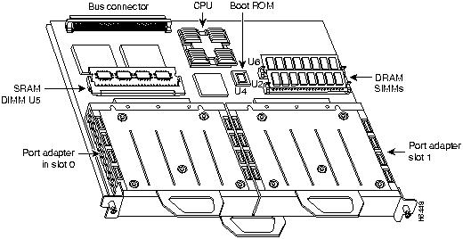
You can install service adapters in VIP2 and Cisco 7200 series port adapter slots. Figure 2 shows a VIP2 with installed port adapters. The VIP2 card, service adapters, and port adapters have handles that allow for easy installation and removal. With the VIP2 oriented as shown in Figure 2, the left slot is port adapter slot 0, and the right slot is port adapter slot 1. In the Cisco 7000, Cisco 7507, and Cisco 7513 chassis, the VIP2 is installed vertically.
Figure 2 : VIP2 Port Adapter Slots (Horizontal Orientation Shown)
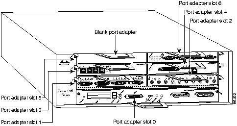
In the Cisco 7200 series, which consist of the Cisco 7204 and the Cisco 7206, port adapter slots are numbered from left to right, beginning with port adapter slot 1 and continuing through port adapter slot 4 for the Cisco 7204, and slot 6 for the Cisco 7206. Port adapter slot 0 is the optional Fast Ethernet port on the I/O controller. Figure 3 shows a Cisco 7206 with port adapters installed.
Figure 3 : Cisco 7200 Series Port Adapter Slots---Cisco 7206 Shown
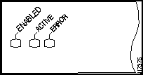
The CSA has an enabled LED, standard on all service adapters, plus the active and error LEDs. After system initialization, the enabled LED goes on to indicate that the CSA has been enabled for operation. (The LEDs are shown in Figure 4.) The following conditions must be met before the enabled LED goes on:
If either of these conditions is not met, or if the router initialization fails for other reasons, the enabled LED does not go on.
In addition to the enabled LED, the CSA has the following two LEDs and indications:
Figure 4 : LEDs on the CSA (Partial Faceplate View)
VIP2 and the Compression Service Adapter
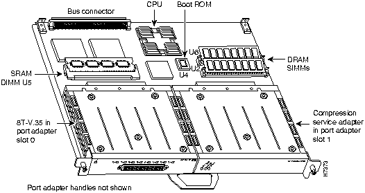
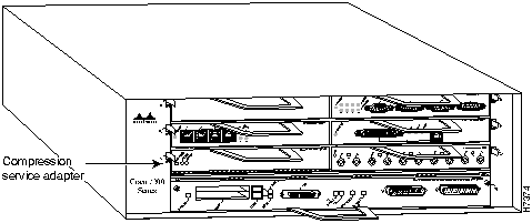
The CSA is used on the VIP2, and can be installed in either port adapter slot 0 or port adapter slot 1; however, the CSA will only compress and decompress data passing through interfaces on the PA-4T or the PA-8T port adapter in the adjacent VIP2 port adapter slot. Figure 5 shows the CSA installed on a VIP2 in port adapter slot 1.
Figure 5 : VIP2 with a Compression Service Adapter in Port Adapter Slot 1
The following sections discuss information specific to the CSA and its use on the VIP2 in Cisco 7000 series and Cisco 7500 series routers:
Installing or Replacing a Service Adapter on a VIP2
Depending on the circumstances, you might need to install a new service adapter on a VIP2 motherboard or replace a failed service adapter in the field. In either case, you need a number 1 Phillips screwdriver, an antistatic mat onto which you can place the removed interface processor, and an antistatic container into which you can place a failed service adapter for shipment back to the factory.
When only one service adapter is installed on a VIP2, a blank service adapter must fill the empty slot to allow the VIP2 and router chassis to conform to electromagnetic interference (EMI) emissions requirements, and so that air flows through the chassis properly. If you plan to install a new service adapter, you must first remove the blank service adapter.
Following is the standard procedure for removing and replacing any type of service adapter on the VIP2:
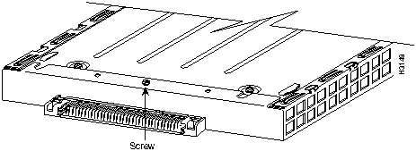
Figure 6 : Location of Service Adapter Screw, Partial Service Adapter View
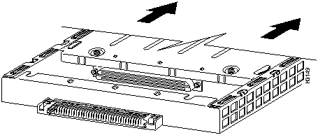
Figure 7 : Pulling a Service Adapter Out of a Slot, Partial Service Adapter View
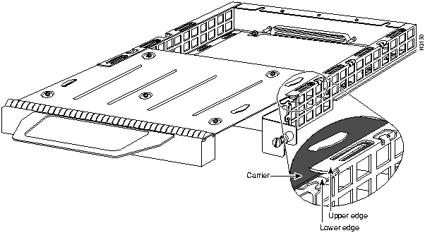
Figure 8 : Installing a Service Adapter
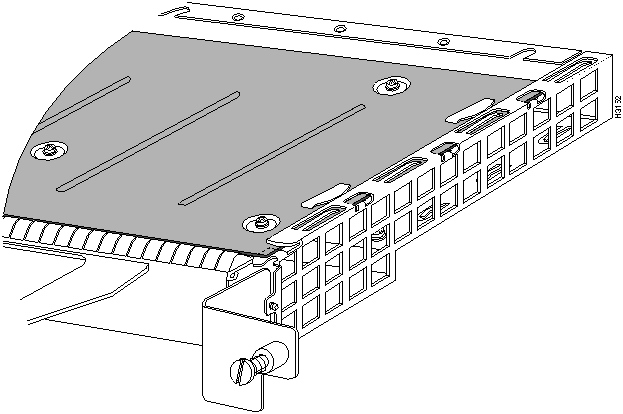
Figure 9 : Aligning the Carrier Edge with Upper and Lower Slot Edges, Partial View
This completes the procedure for installing a new service adapter or replacing a service adapter on a VIP2.
Configuring Compression on VIP2 Interfaces
If you installed a new CSA-equipped VIP2 or if you want to change the configuration of an existing interface, you must enter Configuration mode using the configure command. If you replaced a CSA that was previously configured, the system will recognize the new CSA and bring up each interface previously configured for compression.
After you verify that the new CSA is installed correctly (the enabled LED goes on), use the privileged-level configure command to configure compression on the new interfaces.
The following sections describe the commands for configuring compression on individual interfaces. Configuration commands are executed from the privileged level of the EXEC command interpreter, which usually requires password access. (See the section "Shutting Down an Interface" on page 16.) Refer to the description that follows and contact your system administrator, if necessary, to obtain access.
Selecting Chassis Slot, Port Adapter, and Port Numbers
The following section describes how to identify chassis slot, port adapter, and interface port numbers. You must specify these locations when configuring compression on an interface. A CSA installed in slot 0 or slot 1 of a VIP2 will only compress interfaces on the serial port adapter installed in the adjacent VIP2 slot.
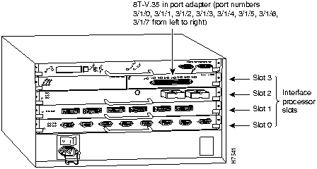
In the router, physical port addresses specify the actual physical location of each interface port on the router interface processor end. (See Figure 10.) This address is composed of a three-part number in the format chassis slot number/port adapter number/interface port number.
Interface ports on the port adapter maintain the same address regardless of whether other interface processors are installed or removed. However, when you move a VIP2 to a different slot, the first number in the address changes to reflect the new slot number.
Figure 10 shows some of the chassis slot, port adapter, and interface ports of a sample Cisco 7505 system. For example, on the 8T-V.35-equipped VIP2 in chassis slot 3, the addresses for the interface ports are 3/1/0 through 3/1/7 (chassis slot 3, port adapter slot 1, and interface ports 0 through 7). If the 8T-V.35 port adapter was in port adapter slot 2, these same interface ports would be numbered 3/2/0 through 3/2/7.
The first port adapter slot number is always 0; the second port adapter slot number is always 1. The individual interface port numbers always begin with 0. The number of additional ports depends on the number of ports on a port adapter. Port adapters can occupy either port adapter slot. There are no restrictions.
Figure 10 : Serial Interface Port Number Example (Cisco 7505 Shown)
You can identify interface ports by physically checking the slot/port adapter/interface port location on the back of the router or by using show commands to display information about a specific interface or all interfaces in the router.
Using the EXEC Command Interpreter
Before you use the configure command to configure interfaces or change an existing configuration, you must enter the privileged level of the EXEC command interpreter with the enable command. The system will prompt you for a password if one has been set.
The system prompt for the privileged level ends with a pound sign (#) instead of an angle bracket (>). At the console terminal, enter the privileged level as follows:
Proceed to the following section "Shutting Down an Interface" for instructions that explain how to shut down an interface.
If you plan to remove an interface that you will not replace, or replace port adapters, shut down (disable) the interfaces to prevent anomalies when you reinstall the new or reconfigured interface processor. When you shut down an interface, it is designated administratively down in the show command displays.
Follow these steps to shut down an interface:
For complete descriptions of software configuration commands, refer to the publications listed in the section "If You Need More Information" on page 2.
Configuring Interfaces for Compression
A CSA installed in slot 0 or slot 1 of a VIP2 will only compress interfaces on the serial port adapter installed in the adjacent VIP2 slot. For Cisco 7500 series routers that have an installed VIP2 with a CSA, there are three methods for configuring PPP compression.
Use the compress stac [software|distributed] command to configure compression on interfaces. The compress stac command used without variables enables hardware compression on a specified interface; if a CSA is not installed in the router, distributed compression is enabled on the interface; if a VIP2 is not installed in the router, software compression is enabled on the interface.
If your Cisco 7500 series router has an installed VIP2 with a CSA, you can force distributed compression on an interface using the compress stac distributed command. You can also force software compression on an interface using the compress stac software command.
Following are instructions for configuring compression on a serial interface. Press the Return key after each step unless otherwise noted. At any time you can exit the privileged level and return to the user level by entering disable at the prompt as follows:
Complete the following steps to configure compression on serial interface using the compress stac [ditributed|software] command:
After removing compression from an interface, the interface will not appear in the output from the show compress command. To check the configuration of the interfaces, proceed to the section "Checking the Configuration."
After configuring the interfaces for compression, use the show commands to display the status of the interfaces, and use the ping and loopback commands to check connectivity.
Using show Commands to Verify Compression and System Configuration
The following steps use show commands to verify that the interfaces are configured and operating correctly.
If the displays indicate that the hardware is not functioning properly, ensure that the network interface is properly connected and terminated. If you still have problems, contact a customer service representative for assistance.
The show version (or show hardware) command displays the configuration of the system hardware (the number of each interface processor type installed), the software version, the names and sources of configuration files, and the boot images. Following is an example of the show version command used with a Cisco 7500 series system:
To determine which interfaces in the router are configured for compression, use the show compress command. All interfaces configured for compression are displayed, as well as the type of compression configured on each interface, as shown in the following example (the show compress command only displays interfaces that are configured for compression):
To determine the type of port adapters installed on a VIP2 in your system, use the show diag slot command. Specific port adapter information is displayed, as shown in the following example of a 8T-V.35 port adapter in chassis slot 3:
If the displays indicate that the hardware is not functioning properly, ensure that the network interfaces are properly connected and terminated. If you still have problems bringing up or shutting down an interface, contact a customer service representative for assistance.
To display information about a specific interface, use the show interfaces command with the interface type and port address in the format show interfaces [type slot/port adapter/port].
Following is an example of how the show interfaces [type slot/port adapter/port] command displays status information (including the physical slot and port address) for the interfaces you specify. In these examples, most of the status information for each interface is omitted, and the eight serial interfaces (0--7) are in chassis slot 3, in port adapter slot 1. (Interfaces are administratively shut down until you enable them.)
With the VIP2 configuration shown in Figure 10, an 8T-V.35 port adapter is in port adapter slot 1. With the show interfaces type slot/port adapter/port command, use arguments such as the interface type (serial, and so forth) and the slot, port adapter, and port numbers (slot/port adapter/port) to display information about a specific serial interface only.
The following example of the show interfaces serial slot/port adapter/port command shows all of the information specific to the first 8T-V.35 interface port (interface port 0) in chassis slot 3, port adapter slot 1:
For complete VIP2 command descriptions and examples, refer to the publications listed in the section "If You Need More Information" on page 2.
Using the ping and loopback Commands The packet internet groper (ping) and loopback commands allow you to verify that an interface port is functioning properly and to check the path between a specific port and connected devices at various locations on the network. You can also use the show compress command to view the interfaces in the router that are configured for compression.
This section provides brief descriptions of the ping and loopback commands. After you verify that the system and VIP2 have booted successfully and are operational, you can use these commands to verify the status of interface ports. Refer to the publications listed in the section "If You Need More Information" on page 2, for detailed command descriptions and examples.
The ping command sends an echo request out to a remote device at an IP address that you specify. After sending a series of signals, the command waits a specified time for the remote device to echo the signals. Each returned signal is displayed as an exclamation point (!) on the console terminal; each signal that is not returned before the specified timeout is displayed as a period (.). A series of exclamation points (!!!!!) indicates a good connection; a series of periods (.....) or the messages [timed out] or [failed] indicate that the connection failed.
Following is an example of a successful ping command to a remote server with the address 1.1.1.10:
If the connection fails, verify that you have the correct IP address for the server and that the server is active (powered on), and repeat the ping command.
The loopback test allows you to detect and isolate equipment malfunctions by testing the connection between a port adapter interface and a remote device such as a modem or a CSU/DSU. The loopback subcommand sends a series of packets out to and through the device (or cable), and back to the port adapter interface. If the packets complete the loop, the connection is good. If not, you can isolate a fault to the remote device or interface cable in the path of the loopback test.
For complete descriptions of interface subcommands and the configuration options available for Cisco 7000 and Cisco 7500 series-related interfaces, refer to the publications listed in the section "If You Need More Information" on page 2.
Cisco 7200 Series Routers and the Compression Service Adapter
The CSA is used in the Cisco 7200 series routers and can be installed in any of the available port adapter slots; however, the Cisco 7200 series routers only support one installed CSA. A CSA installed in a Cisco 7200 series router will compress interfaces on serial port adapters installed in any port adapter slot. Figure 11 shows a CSA installed in port adapter slot 1 of a Cisco 7206.
Figure 11 : Cisco 7206 with a CSA in Port Adapter Slot 1
The following sections include information that is specific to the CSA and its use in the Cisco 7200 series routers:
Installing or Replacing a Port/Service Adapter in Cisco 7200 Series Routers
The following sections explain how to install and replace a new service adapter or port adapter in a Cisco 7200 series router. The steps for doing so are the same; therefore, the term adapter in the following sections applies to service adapters as well as port adapters, unless noted otherwise.
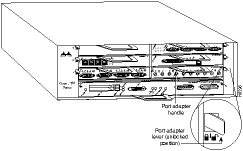
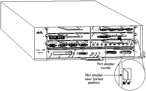
Depending on your circumstances, you might need to install a new adapter in a Cisco 7200 series router or replace a failed adapter in the field. In either case no tools are necessary; all adapters available for the Cisco 7200 series connect directly to the router midplane and are locked into position by a port adapter lever.
When removing and replacing an adapter, you will need an antistatic mat onto which you can place a removed adapter and an antistatic container into which you can place a failed adapter for shipment back to the factory.
When a port adapter slot in a Cisco 7200 chassis is not in use, a blank port adapter must fill the empty slot to allow the router to conform to EMI emissions requirements and to allow proper air flow across the adapters. If you plan to install an adapter in a slot that is not in use, you must first remove the blank port adapter.
Following is the procedure for removing an adapter from a Cisco 7200 series router:
Figure 12 : Placing the Port Adapter Lever in the Unlocked Position (Cisco 7206 shown)
Figure 13 : Handling an Adapter
This completes the procedure for removing an adapter from a Cisco 7200 series router.
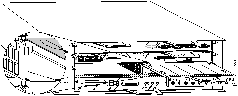
Following is the procedure for installing a new adapter in a Cisco 7200 series router:
Figure 14 : Aligning the Adapter Metal Carrier Between the Slot Guides (Cisco 7206 Shown)
Figure 15 : Placing the Port Adapter Lever in the Locked Position (Cisco 7206 shown)
This completes the procedure for installing a new adapter in a Cisco 7200 series router.
Configuring Compression on 7200 Series Interfaces
If you installed a new CSA or if you want to change the configuration of an existing interface, you must enter Configuration mode using the configure command. If you replaced a CSA that was previously configured, the system will recognize the new CSA and bring up each interface previously configured for compression.
After you verify that the new CSA is installed correctly (the enabled LED goes on), use the privileged-level configure command to configure compression on the new interfaces.
The following sections describe the commands for configuring compression on individual interfaces. Configuration commands are executed from the privileged level of the EXEC command interpreter, which usually requires password access. (See the section "Shutting Down an Interface" on page 16.) Refer to the description that follows and contact your system administrator, if necessary, to obtain access.
Selecting Port Adapter Slot and Interface Port Numbers
The following section describes how to identify port adapter slot and interface port numbers. You must specify these locations when configuring compression on an interface.
Physical port addresses specify the actual physical location of each interface port on the router. (See Figure 16.) This address is composed of a two-part number in the format port adapter slot number/interface port number, as follows:
Interface ports on port adapters maintain the same address regardless of whether other port adapters are installed or removed. However, when you move a port adapter to a different slot, the first number in the address changes to reflect the new slot number.
Figure 16 shows the port adapter slot and interface ports of an 8T-V.35 port adapter in slot 2 of a Cisco 7206 router. The port adapter slot numbers start with 1 and continue through 6 for the Cisco 7206 and continue through 4 for the Cisco 7204 (slot 0 is always reserved for the Fast Ethernet port on the I/O controller---if present). The individual interface port numbers always begin with 0. The number of additional ports depends on the number of ports on a port adapter. Port adapters and service adapters can occupy any port adapter slot. There are no restrictions.
For example, the addresses of the interface ports on the 8T-V.35 port adapter in chassis slot 2 are 2/0 through 2/7 (chassis slot 2 and interface ports 0 through 7). If the 8T-V.35 port adapter was in port adapter slot 1, these same interface ports would be numbered 1/0 through 1/7.
Figure 16 : Serial Interface Port Number Example
You can identify interface ports by physically checking the port adapter slot/interface port location on the front of the router, or by using software commands to display information about a specific interface or all interfaces in the router.
Using the EXEC Command Interpreter
Before you use the configure command to configure the interfaces or change an existing configuration, you must enter the privileged level of the EXEC command interpreter with the enable command. The system will prompt you for a password if one has been set.
The system prompt for the privileged level ends with a pound sign (#) instead of an angle bracket (>). At the console terminal, enter the privileged level as follows:
Proceed to the following section "Shutting Down an Interface" for instructions that explain how to shut down an interface.
If you plan to remove an interface that you will not replace, or replace port adapters, shut down (disable) the interfaces to prevent anomalies when you reinstall the new or reconfigured port adapter. When you shut down an interface, it is designated administratively down in the show command displays.
Follow these steps to shut down an interface:
For complete descriptions of software configuration commands, refer to the publications listed in the section "If You Need More Information" on page 2.
Configuring Interfaces for Compression
A CSA installed in Cisco 7200 series router will compress interfaces on serial port adapters installed in any port adapter slot. For Cisco 7200 series routers that have an installed CSA, there are two methods for configuring PPP compression:
Use the compress stac [software] command to configure compression on interfaces. The compress stac command used without the software variable enables hardware compression on a specified interface; if a CSA is not installed in the router, software compression is enabled on the interface.
If your Cisco 7200 series router has an installed CSA, you can force software compression on an interface using the compress stac software command.
Following are instructions for configuring compression on a serial interface. Press the Return key after each step unless otherwise noted. At any time you can exit the privileged level and return to the user level by entering disable at the prompt as follows:
Complete the following steps to configure compression on a serial interface using the compress stac [software] command:
After removing compression from an interface, the interface will not appear in the output from the show compress command. To check the configuration of the interfaces, proceed to the section "Checking the Configuration."
After configuring the interfaces for compression, use the show commands to display the status of the interfaces and the ping and loopback commands to check connectivity.
Using show Commands to Verify Compression and System Configuration
The following steps use show commands to verify that the interfaces are configured and operating correctly.
If the displays indicate that the hardware is not functioning properly, ensure that the network interface is properly connected and terminated. If you still have problems, contact a customer service representative for assistance.
The show version (or show hardware) command displays the configuration of the system hardware (the number of each interface processor type installed), the software version, the names and sources of configuration files, and the boot images. Following is an example of the show version command used with a Cisco 7500 series system:
To determine which interfaces in the router are configured for compression, use the show compress command. All interfaces configured for compression are displayed, as well as the type of compression configured on each interface, as shown in the following example (the show compress command only displays interfaces that are configured for compression):
To determine the type of port adapters installed in your Cisco 7200 series router, use the show diag slot command. Specific port adapter information is displayed, as shown in the following example of a CSA in chassis slot 1:
If the previous displays indicate that the hardware is not functioning properly, ensure that the network interfaces are properly connected and terminated. If you still have problems bringing up or shutting down an interface, contact a customer service representative for assistance.
To display information about a specific interface, use the show interfaces command with the interface type and port address in the format show interfaces [type port adapter slot/interface port number].
Following is an example of how the show interfaces [type port adapter slot/interface port number] command displays status information (including the physical slot and port address) for the interfaces you specify. In these examples, most of the status information for each interface is omitted, and the eight serial interfaces (0--7) are in port adapter slot 2. (Interfaces are administratively shut down until you enable them.)
With the show interfaces type port adapter slot/interface port number command, use arguments such as the interface type (serial, and so forth), port adapter slot, and the interface port number (port adapter slot/port) to display information about a specific serial interface only.
The following example of the show interfaces serial port adapter slot/interface port number command shows all of the information specific to the first 8T-V.35 interface port adapter in port adapter slot 2:
For complete VIP2 command descriptions and examples, refer to the publications listed in the section "If You Need More Information" on page 2.
Using the ping and loopback Commands
The packet internet groper (ping) and loopback commands allow you to verify that an interface port is functioning properly and to check the path between a specific port and connected devices at various locations on the network. You can also use the show compress command to view the interfaces in the router that are configured for compression.
This section provides brief descriptions of the ping and loopback commands. After you verify that the router and port adapters have booted successfully and are operational, you can use these commands to verify the status of interface ports. Refer to the publications listed in the section "If You Need More Information" on page 2, for detailed command descriptions and examples.
The ping command sends an echo request out to a remote device at an IP address that you specify. After sending a series of signals, the command waits a specified time for the remote device to echo the signals. Each returned signal is displayed as an exclamation point (!) on the console terminal; each signal that is not returned before the specified timeout is displayed as a period (.). A series of exclamation points (!!!!!) indicates a good connection; a series of periods (.....) or the messages [timed out] or [failed] indicate that the connection failed.
Following is an example of a successful ping command to a remote server with the address 1.1.1.10:
If the connection fails, verify that you have the correct IP address for the server and that the server is active (powered on), and repeat the ping command.
The loopback test allows you to detect and isolate equipment malfunctions by testing the connection between a port adapter interface and a remote device such asa modem or a CSU/DSU. The loopback subcommand sends a series of packets out to and through the device (or cable), and back to the port adapter interface. If the packets complete the loop, the connection is good. If not, you can isolate a fault to the remote device or interface cable in the path of the loopback test.
For complete descriptions of interface subcommands and the configuration options available for Cisco 7200 series-related interfaces, refer to the publications listed in the section "If You Need More Information" on page 2.
Copyright 1988-1996 © Cisco Systems Inc.
![]()
![]()
![]()
Router>
enable
Password:
Router#
Router#
configure terminal
Enter configuration commands, one per line. End with CNTL/Z.
Router(config)#
Router(config)#
interface
serial 3/1/0
Router(config-int)#
shutdown
Router(config-int)#
int serial 3/1/1
Router(config-int)#
shutdown
Router(config-int)#
int serial 3/1/2
Router(config-int)#
shutdown
Ctrl-Z
Router#
Router#
copy running-config startup-config
[OK]
Router#
Router#
show int serial 3/1/0
Serial 3/1/0 is administratively down, line protocol is down
Hardware is M8T-V.35
[display text omitted]
Router(config)#
int serial 3/1/0
Router(config-int)#
no shutdown
Ctrl-Z
Router#
Router#
copy running-config startup-config
[OK]
Router#
show int serial 3/1/0
Serial 3/1/0 is up, line protocol is up
Hardware is M8T-V.35
[display text omitted]
Router# disable
Router>
Router#
configure terminal
Enter configuration commands, one per line. End with CNTL/Z.
Router(config)#
Router(config)#
interface
serial 3/1/0
router(config-int)#
encapsulattion PPP
router(config-int)#
compress stac
Router(config-int)#
int serial 3/1/1
Router(config-int)#
compress stac
Router(config-int)#
int serial 3/1/2
Router(config-int)#
compress stac
Ctrl-Z
Router#
Router#
copy running-config startup-config
[OK]
Router#
Router(config)#
int serial 3/1/0
Router(config-int)#
no compress
Ctrl-Z
Router#
Router#
copy running-config startup-config
[OK]
Router# show version

Cisco Internetwork Operating System Software
IOS (tm) GS Software (RSP-A), Version 11.1(6) [amcrae 125]
Copyright (c) 1986-1996 by cisco Systems, Inc.
Compiled Sat 10-Aug-96 17:56 by amcrae
Image text-base: 0x600108A0, data-base: 0x60952000

ROM: System Bootstrap, Version 5.3(16645) [szhang 571], INTERIM SOFTWARE
ROM: GS Software (RSP-BOOT-M), Version 11.1(472), RELEASE SOFTWARE (fc1)

gshen_7500 uptime is 5 days, 4 minutes
System restarted by reload
System image file is "rsp-jv-mz", booted via slot0

cisco RSP2 (R4600) processor with 16384K bytes of memory.
R4600 processor, Implementation 33, Revision 2.0
Last reset from power-on
G.703/E1 software, Version 1.0.
SuperLAT software copyright 1990 by Meridian Technology Corp).
Bridging software.
X.25 software, Version 2.0, NET2, BFE and GOSIP compliant.
TN3270 Emulation software (copyright 1994 by TGV Inc).
Chassis Interface.
1 EIP controller (6 Ethernet).
1 VIP2 controller (8 Serial)(1 Compression).
6 Ethernet/IEEE 802.3 interfaces.
1 HSSI network interface.
1 Compression port adapter.
125K bytes of non-volatile configuration memory.

8192K bytes of Flash PCMCIA card at slot 0 (Sector size 128K).
8192K bytes of Flash internal SIMM (Sector size 256K).
Configuration register is 0x0
Router# sh compress
Serial3/1/0
     Distributed h/w compression enabled
     Compressed bytes sent:      4932 bytes   0 Kbits/sec  ratio: 10.500
     Compressed bytes recv:      5019 bytes   0 Kbits/sec  ratio: 10.019
     restarts: 10
     last clearing of counters: 165828 seconds

 Serial3/1/1
     Distributed h/w compression enabled
     Compressed bytes sent:      4942 bytes   0 Kbits/sec  ratio: 10.700
     Compressed bytes recv:      5029 bytes   0 Kbits/sec  ratio: 10.009
     restarts: 10
     last clearing of counters: 162528 seconds

Serial3/1/2
     Distributed h/w compression enabled
     Compressed bytes sent:      4922 bytes   0 Kbits/sec  ratio: 10.720
     Compressed bytes recv:      5019 bytes   0 Kbits/sec  ratio: 10.119
     restarts: 10
     last clearing of counters: 162528 seconds

Serial3/1/3
     Distributed h/w compression enabled
     Compressed bytes sent:      2836 bytes   0 Kbits/sec  ratio: 8.845
     Compressed bytes recv:      3080 bytes   0 Kbits/sec  ratio: 8.034
     restarts: 9
     last clearing of counters: 162528 seconds
Serial3/1/4
     Distributed h/w compression enabled
     Compressed bytes sent:      2736 bytes   0 Kbits/sec  ratio: 8.835
     Compressed bytes recv:      3180 bytes   0 Kbits/sec  ratio: 8.014
     restarts: 9
     last clearing of counters: 162528 seconds

Serial3/1/5
     Distributed h/w compression enabled
     Compressed bytes sent:      2832 bytes   0 Kbits/sec  ratio: 8.622
     Compressed bytes recv:      3088 bytes   0 Kbits/sec  ratio: 8.321
     restarts: 9
     last clearing of counters: 162528 seconds

Serial3/1/6
     Distributed h/w compression enabled
     Compressed bytes sent:      2110 bytes   0 Kbits/sec  ratio: 8.845
     Compressed bytes recv:      3432 bytes   0 Kbits/sec  ratio: 8.734
     restarts: 9
     last clearing of counters: 162528 seconds

Serial3/1/7
     Distributed h/w compression enabled
     Compressed bytes sent:      2829 bytes   0 Kbits/sec  ratio: 8.335
     Compressed bytes recv:      3676 bytes   0 Kbits/sec  ratio: 8.214
     restarts: 9
     last clearing of counters: 162528 seconds
Router# show diag 3
Slot 3:
        Physical slot 3, ~physical slot 0xF, logical slot 0, CBus 0
        Microcode Status 0x4
        Master Enable, LED, WCS Loaded
        Board is analyzed
        Pending I/O Status: None
        EEPROM format version 1
        VIP2 controller, HW rev 2.1, board revision UNKNOWN
        Serial number: 03341394  Part number: 73-1684-02
        Test history: 0x00        RMA number: 00-00-00
        Flags: cisco 7000 board; 7500 compatible

        EEPROM contents (hex):
          0x20: 01 15 02 01 00 32 FC 52 49 06 94 02 00 00 00 00
          0x30: 07 2E 00 2A 1A 00 00 00 00 00 00 00 00 00 00 00

        Slot database information:
        Flags: 0x4      Insertion time: 0x8E11A48 (04:51:14 ago)


        Controller Memory Size: 8 MBytes DRAM, 1024 KBytes SRAM

        PA Bay 0 Information:
                Compression PA, 3M SRAM, 0 ports
                EEPROM format version 255
                HW rev FF.FF, Board revision UNKNOWN
                Serial number: 4294967295  Part number: 255-65535-255

        PA Bay 1 Information:
                Mueslix Serial PA, 8 ports
                EEPROM format version 1
                HW rev FF.FF, Board revision UNKNOWN
                Serial number: 4294967295  Part number: 255-65535-255
Router# sh int serial 3/1/0
Serial3/1/0 is up, line protocol is up
  Hardware is cyBus Serial
  Internet address is 1.1.1.0
  MTU 1500 bytes, BW 1544 Kbit, DLY 20000 usec, rely 255/255, load 1/255
  Encapsulation PPP, loopback not set, keepalive not set
(display text omitted]

Router# sh int serial 3/1/1
Serial3/1/1 is up, line protocol is up
  Hardware is cyBus Serial
  Internet address is 1.1.1.1
  MTU 1500 bytes, BW 1544 Kbit, DLY 20000 usec, rely 255/255, load 1/255
  Encapsulation PPP, loopback not set, keepalive not set
(display text omitted]

Router# sh int serial 3/1/2
Serial3/1/2 is up, line protocol is up
  Hardware is cyBus Serial
  Internet address is 1.1.1.2
  MTU 1500 bytes, BW 1544 Kbit, DLY 20000 usec, rely 255/255, load 1/255
  Encapsulation PPP, loopback not set, keepalive not set
(display text omitted]

Router# sh int serial 3/1/3
Serial3/1/3 is up, line protocol is up
  Hardware is cyBus Serial
  Internet address is 1.1.1.3
  MTU 1500 bytes, BW 1544 Kbit, DLY 20000 usec, rely 255/255, load 1/255
  Encapsulation PPP, loopback not set, keepalive not set
(display text omitted]


Router# sh int serial 3/1/4
Serial3/1/4 is up, line protocol is up
  Hardware is cyBus Serial
  Internet address is 1.1.1.4
  MTU 1500 bytes, BW 1544 Kbit, DLY 20000 usec, rely 255/255, load 1/255
  Encapsulation PPP, loopback not set, keepalive not set
(display text omitted]

Router# sh int serial 3/1/5
Serial3/1/5 is up, line protocol is up
  Hardware is cyBus Serial
  Internet address is 1.1.1.5
  MTU 1500 bytes, BW 1544 Kbit, DLY 20000 usec, rely 255/255, load 1/255
  Encapsulation PPP, loopback not set, keepalive not set
(display text omitted]

Router# sh int serial 3/1/6
Serial3/1/6 is up, line protocol is up
  Hardware is cyBus Serial
  Internet address is 1.1.1.6
  MTU 1500 bytes, BW 1544 Kbit, DLY 20000 usec, rely 255/255, load 1/255
  Encapsulation PPP, loopback not set, keepalive not set
(display text omitted]

Router# sh int serial 3/1/7
Serial3/1/7 is up, line protocol is up
  Hardware is cyBus Serial
  Internet address is 1.1.1.7
  MTU 1500 bytes, BW 1544 Kbit, DLY 20000 usec, rely 255/255, load 1/255
  Encapsulation PPP, loopback not set, keepalive not set
(display text omitted]
Router# sh int serial 3/1/0
Serial3/1/0 is up, line protocol is up
  Hardware is cyBus Serial
  Internet address is 1.1.1.0
  MTU 1500 bytes, BW 1544 Kbit, DLY 20000 usec, rely 255/255, load 1/255
  Encapsulation PPP, loopback not set, keepalive not set
  Last input 2d18h, output 00:00:54, output hang never
  Last clearing of "show interface" counters never
  Input queue: 0/75/0 (size/max/drops); Total output drops: 0
  Queueing strategy: weighted fair
  Output queue: 0/64/0 (size/threshold/drops)
     Conversations  0/1 (active/max active)
     Reserved Conversations 0/0 (allocated/max allocated)

  5 minute input rate 0 bits/sec, 0 packets/sec
  5 minute output rate 0 bits/sec, 0 packets/sec
     16 packets input, 1620 bytes, 0 no buffer
     Received 0 broadcasts, 0 runts, 0 giants
     0 input errors, 0 CRC, 0 frame, 0 overrun, 1 ignored, 0 abort
     3995 packets output, 1147800 bytes, 0 underruns
     0 output errors, 0 collisions, 0 interface resets
     0 output buffer failures, 0 output buffers swapped out
     1 carrier transitions
     RTS up, CTS up, DTR up, DCD up, DSR up
Router# ping 1.1.1.10 <Return>
Type escape sequence to abort.
Sending 5, 100-byte ICMP Echoes to 1.1.1.10, timeout is 2 seconds:
!!!!!
Success rate is 100 percent (5/5), round-trip min/avg/max = 1/15/64 ms
Router#
![]()

![]()

Router>
enable
Password:
Router#
Router#
configure terminal
Enter configuration commands, one per line. End with CNTL/Z.
Router(config)#
Router(config)#
interface
serial 2/0
Router(config-int)#
shutdown
Router(config-int)#
int serial 2/1
Router(config-int)#
shutdown
Router(config-int)#
int serial 2/2
Router(config-int)#
shutdown
Ctrl-Z
Router#
Router#
copy running-config startup-config
[OK]
Router#
Router#
show int serial 2/0
Serial 2/0 is administratively down, line protocol is down
Hardware is M8T-V.35
[display text omitted]
Router(config)#
int serial 2/0
Router(config-int)#
no shutdown
Ctrl-Z
Router#
Router#
copy running-config startup-config
[OK]
Router#
show int serial 2/0
Serial 2/0 is up, line protocol is up
Hardware is M8T-V.35
[display text omitted]
Router# disable
Router>
Router#
configure terminal
Enter configuration commands, one per line. End with CNTL/Z.
Router(config)#
Router(config)#
interface
serial 2/0
router(config-int)#
encapsulation PPP
router(config-int)#
compress stac
Router(config-int)#
int serial 2/1
Router(config-int)#
compress stac
Router(config-int)#
int serial 2/2
Router(config-int)#
compress stac
Ctrl-Z
Router#
Router#
copy running-config startup-config
[OK]
Router#
Router(config)#
int serial 2/0
Router(config-int)#
no compress
Ctrl-Z
Router#
Router#
copy running-config startup-config
[OK]
Router# show version

Cisco Internetwork Operating System Software
IOS (tm) GS Software (RSP-A), Version 11.1(6) [amcrae 125]
Copyright (c) 1986-1996 by cisco Systems, Inc.
Compiled Sat 10-Aug-96 17:56 by amcrae
Image text-base: 0x600108A0, data-base: 0x60952000

ROM: GS Software (RSP-BOOT-M), Version 11.1(6), RELEASE SOFTWARE (fc1)

gshen_7500 uptime is 5 days, 4 minutes
System restarted by reload
System image file is "rsp-jv-mz", booted via slot0

cisco 7206 (NPE150) processor with 12288K/4096K bytes of memory.
R4700 processor, Implementation 33, Revision 1.0 (Level 2 Cache)
Last reset from power-on
Bridging software.


SuperLAT software copyright 1990 by Meridian Technology Corp.
X.25 software, Version 2.0, NET2, BFE and GOSIP compliant.
TN3270 Emulation software (copyright 1994 by TGV Inc).
Chassis Interface.
4 Ethernet/IEEE 802.3 interfaces.
2 FastEthernet/IEEE 802.3 interfaces.
4 Token Ring /IEEE802.5 interfaces.
12 Serial network interfaces.
1 Compression port adapter.
125K bytes of non-volatile configuration memory.
1024K bytes of packet SRAM memory.

20480K bytes of Flash PCMCIA card at slot 0 (Sector size 128K).
8192K bytes of Flash internal SIMM (Sector size 256K).
Configuration register is 0x2
Router# sh compress
Serial2/0
     Distributed h/w compression enabled
     Compressed bytes sent:      4932 bytes   0 Kbits/sec  ratio: 10.500
     Compressed bytes recv:      5019 bytes   0 Kbits/sec  ratio: 10.019
     restarts: 10
     last clearing of counters: 165828 seconds

 Serial2/1
     Distributed h/w compression enabled
     Compressed bytes sent:      4942 bytes   0 Kbits/sec  ratio: 10.700
     Compressed bytes recv:      5029 bytes   0 Kbits/sec  ratio: 10.009
     restarts: 10
     last clearing of counters: 162528 seconds
Serial2/2
     Distributed h/w compression enabled
     Compressed bytes sent:      4922 bytes   0 Kbits/sec  ratio: 10.720
     Compressed bytes recv:      5019 bytes   0 Kbits/sec  ratio: 10.119
     restarts: 10
     last clearing of counters: 162528 seconds

Serial2/3
     Distributed h/w compression enabled
     Compressed bytes sent:      2836 bytes   0 Kbits/sec  ratio: 8.845
     Compressed bytes recv:      3080 bytes   0 Kbits/sec  ratio: 8.034
     restarts: 9
     last clearing of counters: 162528 seconds
Serial2/4
     Distributed h/w compression enabled
     Compressed bytes sent:      2736 bytes   0 Kbits/sec  ratio: 8.835
     Compressed bytes recv:      3180 bytes   0 Kbits/sec  ratio: 8.014
     restarts: 9
     last clearing of counters: 162528 seconds

Serial2/5
     Distributed h/w compression enabled
     Compressed bytes sent:      2832 bytes   0 Kbits/sec  ratio: 8.622
     Compressed bytes recv:      3088 bytes   0 Kbits/sec  ratio: 8.321
     restarts: 9
     last clearing of counters: 162528 seconds


Serial2/6
     Distributed h/w compression enabled
     Compressed bytes sent:      2110 bytes   0 Kbits/sec  ratio: 8.845
     Compressed bytes recv:      3432 bytes   0 Kbits/sec  ratio: 8.734
     restarts: 9
     last clearing of counters: 162528 seconds

Serial2/7
     Distributed h/w compression enabled
     Compressed bytes sent:      2829 bytes   0 Kbits/sec  ratio: 8.335
     Compressed bytes recv:      3676 bytes   0 Kbits/sec  ratio: 8.214
     restarts: 9
     last clearing of counters: 162528 seconds
Router# sh diag 1
Slot 1:
        Compression engine 768K port adapter, 0 ports
        Port adapter is analyzed
        Port adapter insertion time 00:16:37 ago
        Hardware revision 255.255               Board revision UNKNOWN
        Serial number     4294967295    Part number    255-65535-255
        Test history      0xFF          RMA number     255-255-255
        EEPROM format version 255
        EEPROM contents (hex):
          0x20: FF 09 FF FF FF FF FF FF FF FF FF FF FF FF FF FF
          0x30: FF FF FF FF FF FF FF FF FF FF FF FF FF FF FF FF
Router# sh int serial 2/0
Serial2/0 is up, line protocol is up
  Hardware is M8T-V.35
  Internet address is 1.1.1.0
  MTU 1500 bytes, BW 1544 Kbit, DLY 20000 usec, rely 255/255, load 1/255
  Encapsulation PPP, loopback not set, keepalive not set
(display text omitted]

Router# sh int serial 2/1
Serial2/1 is up, line protocol is up
  Hardware is M8T-V.35
  Internet address is 1.1.1.1
  MTU 1500 bytes, BW 1544 Kbit, DLY 20000 usec, rely 255/255, load 1/255
  Encapsulation PPP, loopback not set, keepalive not set
(display text omitted]


Router# sh int serial 2/2
Serial2/2 is up, line protocol is up
  Hardware is M8T-V.35
  Internet address is 1.1.1.2
  MTU 1500 bytes, BW 1544 Kbit, DLY 20000 usec, rely 255/255, load 1/255
  Encapsulation PPP, loopback not set, keepalive not set
(display text omitted]

Router# sh int serial 2/3
Serial2/3 is up, line protocol is up
  Hardware is M8T-V.35
  Internet address is 1.1.1.3
  MTU 1500 bytes, BW 1544 Kbit, DLY 20000 usec, rely 255/255, load 1/255
  Encapsulation PPP, loopback not set, keepalive not set
(display text omitted]

Router# sh int serial 2/4
Serial2/4 is up, line protocol is up
  Hardware is M8T-V.35
  Internet address is 1.1.1.4
  MTU 1500 bytes, BW 1544 Kbit, DLY 20000 usec, rely 255/255, load 1/255
  Encapsulation PPP, loopback not set, keepalive not set
(display text omitted]

Router# sh int serial 2/5
Serial2/5 is up, line protocol is up
  Hardware is M8T-V.35
  Internet address is 1.1.1.5
  MTU 1500 bytes, BW 1544 Kbit, DLY 20000 usec, rely 255/255, load 1/255
  Encapsulation PPP, loopback not set, keepalive not set
(display text omitted]

Router# sh int serial 2/6
Serial2/6 is up, line protocol is up
  Hardware is M8T-V.35
  Internet address is 1.1.1.6
  MTU 1500 bytes, BW 1544 Kbit, DLY 20000 usec, rely 255/255, load 1/255
  Encapsulation PPP, loopback not set, keepalive not set
(display text omitted]

Router# sh int serial 2/7
Serial2/7 is up, line protocol is up
  Hardware is M8T-V.35
  Internet address is 1.1.1.7
  MTU 1500 bytes, BW 1544 Kbit, DLY 20000 usec, rely 255/255, load 1/255
  Encapsulation PPP, loopback not set, keepalive not set
(display text omitted]
Router# sh int serial 2/0
Serial2/0 is up, line protocol is up
  Hardware is M8T-V.35
  Internet address is 1.1.1.0
  MTU 1500 bytes, BW 1544 Kbit, DLY 20000 usec, rely 255/255, load 1/255
  Encapsulation PPP, loopback not set, keepalive not set
  LCP Open
  Open: ccp, ipcp, cdp
  Last input 00:00:07, output 00:00:05, output hang never
  Last clearing of "show interface" counters 3d23h
  Queueing strategy: fifo
  Output queue 0/40, 0 drops; input queue 0/75, 0 drops
  5 minute input rate 0 bits/sec, 0 packets/sec
  5 minute output rate 0 bits/sec, 0 packets/sec
     5743 packets input, 1886943 bytes, 0 no buffer
     Received 0 broadcasts, 0 runts, 0 giants
     0 input errors, 0 CRC, 0 frame, 0 overrun, 0 ignored, 0 abort
     5743 packets output, 189253 bytes, 0 underruns
     0 output errors, 0 collisions, 4 interface resets
     0 output buffer failures, 0 output buffers swapped out
     4 carrier transitions     DCD=up  DSR=up  DTR=up  RTS=up  CTS=up
Router# ping 1.1.1.10 <Return>
Type escape sequence to abort.
Sending 5, 100-byte ICMP Echoes to 1.1.1.10, timeout is 2 seconds:
!!!!!
Success rate is 100 percent (5/5), round-trip min/avg/max = 1/15/64 ms
Router#

![]()
![]()
![]()
![]()
![]()
![]()
![]()
![]()