|
|
Versatile Interface Processor (VIP2) Installation, Configuration, and Maintenance
Product Numbers: VIP2-10(=), VIP2-20(=), and VIP2-40(=)
This configuration note is a standalone publication that provides instructions for installing, configuring, and maintaining the second-generation Versatile Interface Processor (VIP2) in all Cisco 7500 series routers, and in Cisco 7000 series routers using the 7000 Series Route Switch Processor (RSP7000) and 7000 Series Chassis Interface (RSP7000CI). See the section "Software and Hardware Prerequisites," on page 11, for specific compatibility requirements.
Included in this configuration note are steps for VIP2 hardware installation, and basic VIP2 configuration steps and examples. Also included are maintenance procedures for upgrading user-configurable VIP2 components. A table of contents is included so you can more easily find what you need.
For complete descriptions of interface subcommands and the configuration options available for VIP2-related interfaces, and which support VIP2 functionality, refer to the appropriate Cisco Internetwork Operating System (Cisco IOS) configuration publications listed in the section "If You Need More Information" on page 3.
This configuration note includes the following sections:
The Cisco Internetwork Operating System (Cisco IOS) software running your router contains extensive features and functionality. The effective use of many of many of these features is easier if you have more information at hand. For additional information on configuring and maintaining the Cisco 7000 family routers and VIP2, the following documentation resources are available to you:
cs-rep@cisco.com
. You can also refer to the Cisco Information Packet that shipped with your router.
What Is the Cisco 7000 Series?
The Cisco 7000 series consists of the Cisco 7000 and Cisco 7010 routers. The VIP2 will operate in the Cisco 7000 series routers providing these routers have the 7000 Series Route Switch Processor (RSP7000) and 7000 Series Chassis Interface (RSP7000CI) installed. For software and hardware requirements, refer to the section "Software and Hardware Prerequisites" on page 11.
Network interfaces reside on modular interface processors, including the VIP2, which are inserted into interface processor slots and provide a direct connection between external networks and the high-speed CxBus in the Cisco 7000 series. The Cisco 7000 series supports any combination of available VIP2 port adapter-based network interface types.
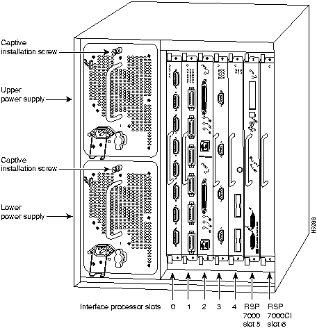
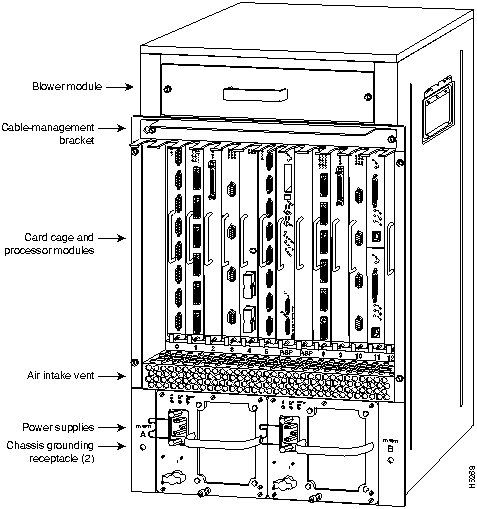
In the Cisco 7000, slot 5 is reserved for the RSP7000 (7000 RSP slot shown in Figure 1), which contains the system processor and performs packet switching functions, and slot 6 is reserved for the RSP7000CI (7000 CI slot shown in Figure 1), which contains all of the environmental monitoring functions for the Cisco 7000. The remaining five slots (slots 0 through 4) are for interface processors and any combination of VIP2 network interface types.
Figure 1 : Cisco 7000 with RSP7000 and RSP7000CI Installed, Interface Processor End
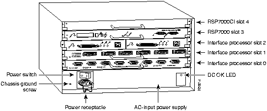
In the Cisco 7010, slot 3 is reserved for the RSP7000 (7000 RSP slot shown in Figure 2), which contains the system processor and performs packet switching functions, and slot 4 is reserved for the RSP7000CI (7000 CI slot shown in Figure 2), which contains all of the environmental monitoring functions for the Cisco 7010. The remaining three slots (slots 0 through 2) are for interface processors and any combination of VIP2 network interface types.
Figure 2 : Cisco 7010 with RSP7000 and RSP7000CI Installed, Interface Processor End
What Is the Cisco 7500 Series?
The Cisco 7500 series consists of the Cisco 7505, Cisco 7507, and Cisco 7513 routers. The VIP2 will operate in the Cisco 7500 series routers. For software and hardware requirements, refer to the section "Software and Hardware Prerequisites" on page 11.
Network interfaces reside on modular interface processors, including the VIP2, which are inserted into interface processor slots and provide a direct connection between external networks and the high-speed CyBus in the Cisco 7500 series. The Cisco 7000 series supports any combination of available VIP2 port adapter-based network interface types.
Figure 3, Figure 4, and Figure 5 show the rear of the Cisco 7500 series routers: the five-slot Cisco 7505, the seven-slot Cisco 7507, and the thirteen-slot Cisco 7513, respectively.
In the Cisco 7505 (see Figure 3), one slot (4) is reserved for the Route Switch Processor (RSP1), which contains the system processor and performs packet switching functions. Slots 0 through 3 are for interface processors and any combination of VIP2 network interface types.
Figure 3 : Cisco 7505, Interface Processor End
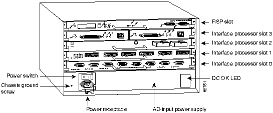
Figure 4 shows the rear of the seven-slot Cisco 7507 router. In the Cisco 7507, up to two slots (2 and 3) are reserved for the Route Switch Processor (RSP2), which contains the system processor and performs packet switching functions. Slots 0 and 1 and 4 through 6 are for interface processors and any combination of VIP2 network interface types.
Figure 4 : Cisco 7507, Interface Processor End
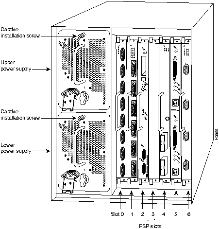
Figure 5 shows the rear of the Cisco 7513 with two AC-input power supplies installed. Two slots (6 and 7) are reserved for the second generation Route Switch Processor (RSP2), which contains the system processor and performs packet switching functions. Slots 0 through 5 and 8 through 12 are for interface processors and any combination of VIP2 network interface types.
Figure 5 : Cisco 7513, Interface Processor End
Versatile Interface Processor Functions
The following sections describe the VIP2 and discuss VIP2-specific features and functions, such as installing and removing the VIP2, installing and removing port adapters, upgrading dynamic random access memory (DRAM) and static random-access memory (SRAM), and using and configuring common VIP2 interface functions.
The VIP2 is the second generation of the new interface processor for use with the Cisco 7000 series routers, using the RSP7000, and Cisco 7500 series routers. The VIP2 installs in the interface processor slots in your 7000 family router.
The VIP2 uses a single motherboard with up to two port adapters. The VIP2 port adapters provide the individual LAN, WAN, or LAN/WAN interface ports. The VIP2 can be removed from a chassis while power is on and the system is operating.
The current VIP2 products have the following DRAM and SRAM configurations:
The VIP2's central processing unit (CPU) is a Reduced Instructions Set Computing (RISC), Mips 4700 processor, and has an internal operating frequency of 100 megahertz (MHz) and a 50-MHz system bus interface. The VIP2 has 128 KB of nonvolatile random-access memory (NVRAM).
The VIP2-10 has 512 KB of static random-access memory (SRAM) and 8 megabytes (MB) of dynamic random access memory (DRAM) as the default memory configuration, and can support the following SRAM and DRAM memory-configuration upgrades:
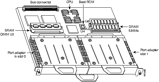
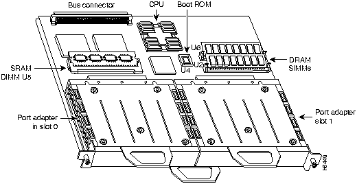
Figure 6 shows a VIP2 with installed port adapters. The VIP2 card and port adapters have handles that allow for easy installation and removal. The VIP2 firmware (microcode), which contains card-specific software instructions, resides in a programmable read-only memory (PROM) device. Single in-line memory modules (SIMMs) contain the DRAM (U1 and U2) and a dual in-line memory module (DIMM) contains the SRAM (U5). You can install VIP2s in any available interface processor slots in your Cisco 7000 family router.
Figure 6 : VIP2 with Two Port Adapters (Horizontal Orientation Shown)
Port Adapter Hardware Overview
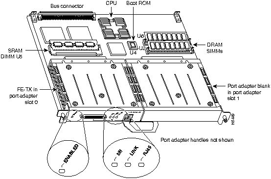
The port adapters attach to the VIP2 motherboard. (See Figure 6.) Each port adapter contains the physical connections for the VIP2 interface types to connect to your network. Following are the electrical interfaces supported by the VIP2 port adapters:
Figure 7 : VIP2 with One FE-TX Port Adapter and a Blank Port Adapter Installed
Software and Hardware Prerequisites
The VIP2 operates with the CyBus in the Cisco 7500 series and, depending on your VIP2 port adapter configuration and protocol requirements, requires that the host routers are running Cisco IOS Release 11.1(472) or later.
The VIP2 operates with the CxBus in the Cisco 7000 series routers providing these routers have the RSP7000 and RSP7000CI installed, and depending on your VIP2 port adapter configuration and protocol requirements, that the host routers are running Cisco IOS Release 11.1(472) or later. For proper operation with the VIP2, we recommend that your RSP or RSP7000 has at least 24 MB of DRAM.
Table 1 : RSP/VIP Cisco IOS Release Subsets
Table 2 : VIP2 Model Minimum Recommendations for Using DSW and DS
Table 3 : Recommended VIP2 Models Based on Network Size
The VIP2 microcode (firmware) is an image that provides card-specific software instructions. A programmable read-only memory (PROM) device on the VIP2 contains a default microcode boot image that assists the system in finding and loading the microcode image from the Cisco IOS bundle or Flash memory. The router supports downloadable microcode, which enables you to upgrade microcode versions by downloading new microcode images, storing them in system Flash memory, and instructing the system to load its image from Flash. You can store multiple images for an interface type and, with a configuration command, instruct the system to load any one of them or the default microcode image. The microcode boot image in the PROM initializes the VIP2 and then assists downloading the VIP2 microcode image. All interfaces of the same type (VIP2, and so on) will load the same microcode image, either from the microcode image bundled with the Cisco IOS or from an image stored in system Flash. Although multiple microcode versions for a specific interface type can be stored concurrently in Flash, only one image can load at startup.
The show controllers cbus command displays the currently loaded and running microcode version for each interface processor, and VIP2. The show startup-config EXEC command shows the current system instructions for loading microcode at startup.
Software and interface processor microcode images are carefully optimized and bundled to work together. Overriding the bundle can result in system incompatibilities. We recommend that you use the microcode included in the software bundle. For a complete description of microcode and downloading procedures, refer to the section "Upgrading VIP2 Microcode" on page 27.
This section provides a list of parts and tools you will need to perform the installation, and it also includes safety and ESD-prevention guidelines to help you avoid injury and damage to the equipment. This section also provides a detailed description of the OIR function to help you perform online installation successfully and avoid error message and system restarts.
You need the following tools and parts to install or upgrade a VIP2. If you need additional equipment, contact a service representative for ordering information.
Following are safety guidelines that you should follow when working with any equipment that connects to electrical power or telephone wiring.
Electrical Equipment Guidelines Follow these basic guidelines when working with any electrical equipment:
Telephone Wiring Guidelines Use the following guidelines when working with any equipment that is connected to telephone wiring or to other network cabling:
Preventing Electrostatic Discharge Damage Electrostatic discharge (ESD) damage, which can occur when electronic cards or components are improperly handled, results in complete or intermittent failures. Port adapters and processor modules comprise printed circuit boards that are fixed in metal carriers. Electromagnetic interference (EMI) shielding and connectors are integral components of the carrier. Although the metal carrier helps to protect the board from ESD, use a preventive antistatic strap during handling.
Following are guidelines for preventing ESD damage:
Online Insertion and Removal---An Overview
The OIR feature allows you to remove and replace a VIP2 board while the system is operating; you do not need to notify the software or shut down the system power.
This section describes mechanical functions of system components, emphasizes the importance of following correct procedures to avoid unnecessary board failures, and is for background only; specific VIP2 procedures follow in the section "VIP2 Installation" on page 19.
Each interface processor contains a receptacle with which it connects to the system backplane. Each backplane connector comprises a set of tiered pins, in three lengths. The pins send specific signals to the system as they make or break contact with the card.
The system assesses the signals it receives and the order in which it receives them to determine what event is occurring and what task it needs to perform, such as reinitializing new interfaces or shutting down removed ones.
For example, when inserting an interface processor, the longest pins make contact with the backplane first, and the shortest pins make contact last. The system recognizes the signals and the sequence in which it receives them. The system expects to receive signals from the individual pins in this logical sequence, and the ejector levers help to ensure that the pins mate in this sequence.
When you remove or insert an interface processor, the backplane pins send signals to notify the system, which then performs as follows:
The system brings on line only interfaces that match the current configuration and were previously configured as up; all others require that you configure them with the configure command. OIR functionality enables you to add, remove, or replace interface processors with the system online, which provides a method that is seamless to end users on the network, maintains all routing information, and ensures session preservation.
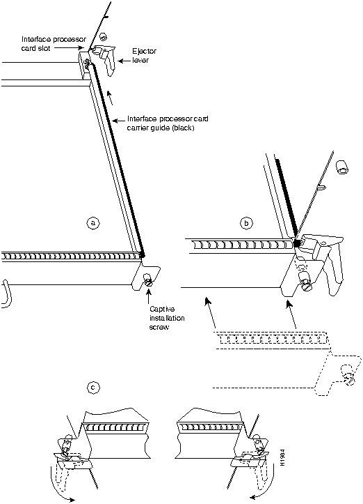
The function of the ejector levers (see Figure 8) is to align and seat the card connectors in the backplane. Failure to use the ejector levers and insert the interface processor properly can disrupt the order in which the pins make contact with the card or interface processor. Follow the VIP2 installation and removal instructions carefully, and review the following examples of incorrect insertion practices and their results:
Use the ejector levers when removing an interface processor to ensure that the backplane connector pins disconnect from the interface processor in the sequence expected by the system. Any interface processor that is only partially connected to the backplane can hang the bus. Steps for correctly performing OIR are included with the following procedures for installing and removing the VIP2.
Figure 8 : Ejector Levers and Captive Installation Screws on the VIP2 (Horizontal Orientation Shown)
The following sections describe the procedures for removing or installing a VIP2 in the Cisco 7000 family routers. The functionality is the same for each router model; therefore, the term the chassis will be used except where specific model issues arise. The OIR function allows you to install and remove a VIP2 without first shutting down the system; however, you must follow the instructions carefully. Failure to insert the VIP2 properly can cause system error messages indicating a board failure. For a complete description of OIR, refer to the section "Online Insertion and Removal---An Overview" on page 16.
Each unused interface processor slot contains an interface processor filler (which is an interface processor carrier without an interface board) to keep dust out of the chassis and to maintain proper air flow through the interface processor compartment. If you are installing a new VIP2 that is not a replacement, you must first remove the interface processor filler from an unused slot; proceed to the next section "Removing an Interface Processor or Interface Processor Filler." If you are replacing a VIP2, proceed to the section "Removing a VIP2."
Removing an Interface Processor or Interface Processor Filler
If you plan to replace a currently installed interface processor with a VIP2, attach an ESD-preventive wrist strap between you and any unpainted chassis surface; interface processor fillers do not require protection from ESD. Select an interface processor slot for the new VIP2 and remove the interface processor or interface processor filler as follows:
To help prevent dust and contaminants from entering the chassis, do not leave the interface processor slot open. Immediately proceed to the section "Installing a VIP2" on page 21.
Remember, the VIP2 supports OIR; therefore, you need not shut down the interface or the system power when removing a VIP2 or interface processor. If you are replacing a failed VIP2, remove the existing board first, then install the new VIP2 in the same slot. If you are replacing a currently installed interface processor with a VIP2, remove the existing board first, then install the new VIP2 in the same slot.
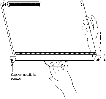
Figure 9 shows proper handling of an interface processor during installation.
Figure 9 : Handling Processor Modules for Installation and Removal (Horizontal Orientation Shown)
To remove a VIP2 or interface processor, follow these steps:
The VIP2 slides into the open interface processor slot and connects directly to the backplane. The interface processors are keyed to guide pins on the backplane, so the VIP2 can be installed only in an interface processor slot. Figure 8 shows the functional details of inserting an interface processor and using the ejector levers. Figure 9 shows proper handling of an interface processor during installation.
Follow these steps to install a VIP2:
Checking the Installation and Verifying VIP2 Status
You can use the configure command to configure a VIP2 interface. To use the configure command, enter the privileged level of the EXEC command interpreter with the enable command. The system will prompt you for a password if one has been set.
The system prompt for the privileged level ends with a pound sign (#) instead of an angle bracket (>). At the console terminal, enter the privileged level as follows:
Checking the VIP2 Installation
After you install the VIP2 and connect cables (using connection procedures in the respective port adapter subsections), verify the installation by observing the LED states and the console display. When the system has reinitialized all interfaces, the enabled LED on the VIP2 and on all interface processors should go on. Port adapter LEDs should be on, depending on your connection. The console screen will also display a message as the system discovers each interface during its reinitialization.
When you remove and replace interface processors, the system provides status messages on the console screen. The messages are for information only. The following sample display shows the events logged by the system as a Fast Ethernet-equipped VIP2 was removed from slot 2; the system then reinitialized the remaining interface processors and marked as down the Fast Ethernet interfaces on the VIP2 that was removed from slot 2. When the VIP2 is reinserted, the system automatically brings up the interfaces that were up when the VIP2 was removed.
Removal
Insertion
The following example display shows the events logged by the system as a new VIP2 is inserted in slot 3. (Fast Ethernet interfaces are used in the following examples.)
Verify that the VIP2 is installed correctly as follows:
If an error message is displayed on the console terminal, refer to the System Error Messages publication for error message definitions. If you experience other problems that you are unable to solve, contact a service representative for assistance.
This completes the VIP2 installation. If you installed a new VIP2 or if you installed a replacement VIP2 with an additional port, you must now configure the new interface as described in the following section and in the appropriate Cisco IOS configuration documentation listed in the section "If You Need More Information" on page 3, all of which is available on CCO and Cisco Connection Documentation, Enterprise Series.
Verifying VIP2 Status Using show Commands
The following procedure describes how to use the show commands to verify that the new interfaces are configured correctly:
If the interface is down and you configured it as up, or if the displays indicate that the hardware is not functioning properly, ensure that the network interface is properly connected and terminated. If you still have problems bringing the interface up, contact a service representative for assistance.
The show controllers cbus command displays the internal status of each interface processor, including the slot location, the card hardware version, and the currently-running microcode version. It also lists each interface (port) on each interface processor including the logical interface number, interface type, physical (slot/port adapter/port) address, and hardware (station address) of each interface. The following example shows a VIP2, with Fast Ethernet interfaces (port adapters), installed in interface processor slot 1:
To determine which type of port adapter is installed on a specific VIP2 in your system, use the show diag slot command. Specific port adapter information is displayed: chassis slot, VIP2 controller information (including hardware revision, serial number, part number, DRAM size, and so forth), and specific port adapter information (including port adapter slot [or bay], port adapter type, number of interfaces, hardware revision, serial number, and part number). Following is an example of the show diag slot command (with samples of several different port adapters included):
(The following is what is displayed for a FE-FX port adapter in port adapter slot 0.)
Serial number: 02826254 Part number: 73-1690-02
(The following is what is displayed for a 4T port adapter in port adapter slot 0.)
(The following is what is displayed for a 4R port adapter in port adapter slot 0.)
(The following is what is displayed for a 5EFL port adapter in port adapter slot 1.)
(The following is what is displayed for PA-FDDI-SM in port adapter slot 0 and PA-FDDI-MM in port adapter slot 1.)
(Where Part number in the last line refers to a PA-FDDI-SM port adapter.)
(Where Part number in the last line refers to a PA-FDDI-MM.)
(The following is what is displayed for a 4E port adapter in port adapter slot 1.)
(The following is what is displayed for a 8E port adapter in port adapter slot 1.)
The show startup-config command displays the contents of the system configuration file stored in nonvolatile memory (NVRAM or Flash memory). This file should reflect all new configuration changes you made and wrote to memory with the show running-config command. (A Fast Ethernet interface is used in this example.)
The show protocols command displays the global (system-wide) and interface-specific status of any configured Level 3 protocol.
The following sections discuss maintenance procedures you might need for your VIP2 and port adapters:
The Cisco 7000 family routers support downloadable microcode, which enables you to upgrade microcode versions over the network. You can download new microcode versions and store multiple versions in Flash memory, and you can then boot from them just as you can with the system software images. System software upgrades may also contain upgraded microcode images, which will load automatically when the new software image is loaded (unless the configuration states otherwise).
You can download microcode to Flash memory by copying the TFTP image of a microcode version to Flash memory. When the microcode image is stored in Flash memory you have to configure the router to use that image via the microcode vip2 flash command, then you can use the microcode reload command to manually load the new microcode file. You can then use the configure command to instruct the system to load the new image automatically at each system boot.
To compare the size of the microcode image and the amount of Flash memory available, you must know the size of the new microcode image. The image size is specified in the README file that is included on the floppy disk with the new image.
Follow these steps to download (copy) a microcode version from a TFTP server to Flash memory.
This completes the procedure for downloading microcode to Flash memory.
The following procedures describe the steps required to upgrade the two DRAM single in-line memory modules (SIMMs) and the one SRAM dual in-line memory module (DIMM) on the VIP2, or to replace the DRAM or SRAM if a system problem has indicated their replacement. Depending on your system configuration and the Cisco IOS your system is running, you might need to upgrade DRAM and SRAM. The current VIP2 products have the following DRAM and SRAM configurations and available VIP2 upgrade products:
The following sections describe upgrading DRAM and SRAM:
The DRAM on the VIP2 is contained in two SIMMs located in sockets U1 and U2. (See Figure 10.) Depending on your system configuration, a memory upgrade might be required. Also, if a system problem is determined to be caused by a SIMM, a SIMM replacement might be required. Use the following procedures to replace the DRAM SIMMs on your VIP2.
Removing SIMMs Follow these steps to remove the existing SIMMs:
Figure 10 : Location of DRAM SIMMs on VIP2
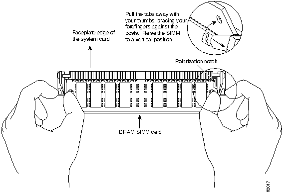
Figure 11 : Releasing the SIMM Spring Clips
This completes the SIMM removal procedure. Proceed to the next section to install the new SIMMs.
Installing New SIMMs SIMMs are sensitive components that are susceptible to ESD damage. Handle SIMMs by the edges only; avoid touching the memory modules, pins, or traces (the metal fingers along the connector edge of the SIMM). (See Figure 12.)
Follow these steps to install the new SIMMs:
This completes the SIMM replacement procedure. Proceed to the section "Replacing the VIP2 SRAM DIMM."
The SRAM on the VIP2 is contained in a DIMM and located in socket U5. (See Figure 10 on page 30.) Depending on your system configuration, a memory upgrade might be required. Also, if a system problem is determined to be caused by the DIMM, a DIMM replacement might be required. Use the following procedures to replace the SRAM DIMM on your VIP2.
Removing the DIMM
Follow these steps to remove the existing DIMM:
Figure 13 : Releasing the SRAM DIMM
This completes the DIMM removal procedure. Proceed to the next section to install the new DIMM.
Installing a New DIMM
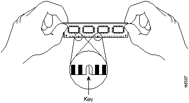
The DIMM is sensitive component that is susceptible to ESD damage. Handle the DIMM by the edges only; avoid touching the memory modules, pins, or traces (the metal fingers along the connector edge of the DIMM). (See Figure 14.)
Figure 14 : Handling an SRAM DIMM
Follow these steps to install the new DIMM:
Figure 15 : Installing and SRAM DIMM in the Socket
This completes the DIMM replacement procedure.
Proceed to the section "Installing a VIP2" to replace the VIP2 in the chassis; then restart the system for an installation check. Refer to the section "Checking a DRAM and SRAM Upgrade."
Checking a DRAM and SRAM Upgrade
If, after a DRAM or SRAM upgrade or replacement, the system fails to boot properly, or if the console terminal displays a checksum or memory error, check the following:
Refer to the section "Checking the VIP2 Installation," on page 22, as required. If after several attempts the system fails to restart properly, contact a service representative for assistance. Before you call, make note of any error messages, unusual LED states, or any other indications that might help solve the problem.
Installing or Replacing a VIP2 Port Adapter
Depending on the circumstances you might need to install a new port adapter on a VIP2 motherboard or replace a failed port adapter in the field. In either case, you need a number 1 Phillips screwdriver, an antistatic mat onto which you can place the removed interface processor, and an antistatic container into which you can place a failed port adapter for shipment back to the factory.
When only one port adapter is installed on a VIP2, a blank port adapter must fill the empty slot to allow the VIP2 and router chassis to conform to electromagnetic interference (EMI) emissions requirements, and so that air flows through the chassis properly. If you plan to install a new port adapter, you must first remove the blank port adapter.
Following is the standard procedure for removing and replacing any type of port adapter on the VIP2:
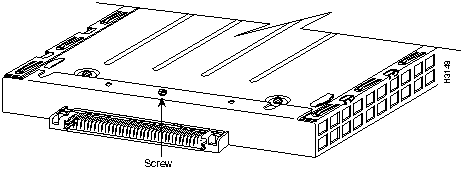
Figure 16 : Location of Port Adapter Screw, Partial Port Adapter View
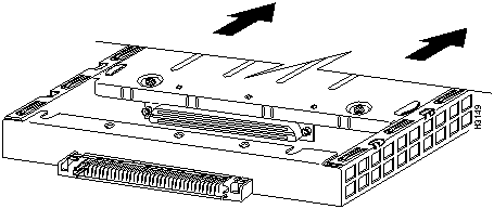
Figure 17 : Pulling a Port Adapter Out of a Slot, Partial Port Adapter View
Figure 18 : Removing a Port Adapter
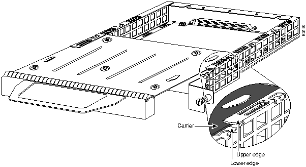
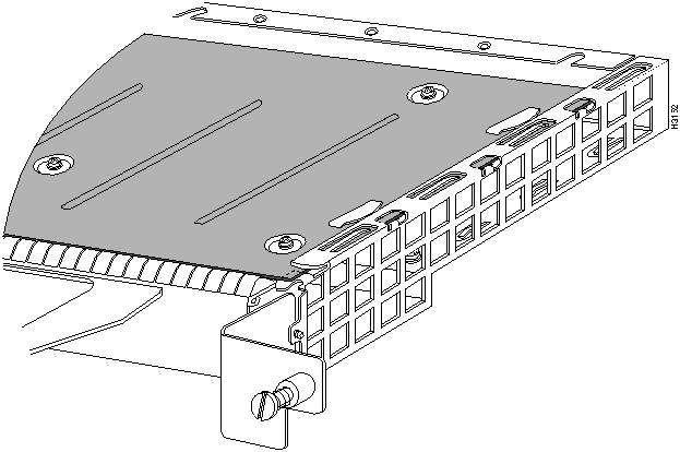
Figure 19 : Aligning the Carrier Edge with Upper and Lower Slot Edges, Partial View
This completes the procedure for installing a new port adapter or replacing a port adapter.
Cisco Connection Online (CCO), formerly Cisco Information Online (CIO), is Cisco Systems' primary, real-time support channel. Maintenance customers and partners can self-register on CCO to obtain additional content and services.
Available 24 hours a day, 7 days a week, CCO provides a wealth of standard and value-added services to Cisco's customers and business partners. CCO services include product information, software updates, release notes, technical tips, the Bug Navigator, configuration notes, brochures, descriptions of service offerings, and download access to public and authorized files.
CCO serves a wide variety of users through two interfaces that are updated and enhanced simultaneously---a character-based version and a multimedia version that resides on the World Wide Web (WWW). The character-based CCO supports Zmodem, Kermit, Xmodem, FTP, and Internet e-mail, and is excellent for quick access to information over lower bandwidths. The WWW version of CCO provides richly formatted documents with photographs, figures, graphics, and video, as well as hyperlinks to related information.
You can access CCO in the following ways:
For a copy of CCO's Frequently Asked Questions (FAQ), contact ccohelp@cisco.com. For additional information, contact ccoteam@cisco.com.
Copyright 1988-1996 © Cisco Systems Inc.
![]()
![]()
Cisco IOS Subset Images
Description
rsp-ajv-mz.111-472
Enterprise plus APPN
rsp-jv-mz.111-472
Enterprise
rsp-pv-mz.111-472
Internet Service Provider
VIP2 Models
Recommended for DSW
Recommended for DS
VIP2--10: 512 KB of SRAM and 8 MB of DRAM
No
No
VIP2-20: 1 MB of SRAM and 16 MB of DRAM
Yes
No
VIP2--40: 2 MB of SRAM and 32 MB of DRAM
Yes
Yes
Number of network nodes
Less than 40,000
Greater than 40,000
VIP21 model to use
VIP2-20
VIP2-40
1 Recommended.
![]()
![]()
![]()
![]()
![]()
![]()
![]()
![]()
Router>
enable
Password:
Router#
Router#
%OIR-6-REMCARD: Card removed from slot 2, interfaces disabled
%LINK-5-CHANGED: Interface FastEthernet2/0/0, changed state to administratively down
%LINK-5-CHANGED: Interface FastEthernet2/1/0, changed state to administratively down
Router#
%OIR-6-INSCARD: Card inserted in slot 2, interfaces administratively shut down
%LINK-5-CHANGED: Interface FastEthernet2/0/0, changed state to up
%LINK-5-CHANGED: Interface FastEthernet2/1/0, changed state to up
Router#
%OIR-6-INSCARD: Card inserted in slot 3, interfaces administratively shut down
%LINK-5-CHANGED: Interface FastEthernet3/0/0, changed state to administratively down
%LINK-5-CHANGED: Interface FastEthernet3/1/0, changed state to administratively down
Router# show controllers cbus

(display text omitted)

slot1: VIP2, hw 2.2, sw 200.47, ccb 5800FF40, cmdq 48000088, vps 8192
    software loaded from flash slot1:svip200-47.fasttq
    FLASH ROM version 255.255
    FastEthernet1/0/0, addr 0000.0ca6.3321 (bia 0000.0ca6.3321)
      gfreeq 48000148, lfreeq 48000188 (1536 bytes), throttled 0
      rxlo 4, rxhi 240, rxcurr 16, maxrxcurr 16
      txq 48000200, txacc 48000202 (value 0), txlimit 150
    FastEthernet1/1/0, addr 0000.0ca6.3329 (bia 0000.0ca6.3329)
      gfreeq 48000148, lfreeq 48000288 (1536 bytes), throttled 0
      rxlo 4, rxhi 240, rxcurr 16, maxrxcurr 16
      txq 48000208, txacc 4800020A (value 0), txlimit 150

(display text omitted)
Router# show diag 1
Slot 1:
        Physical slot 1, ~physical slot 0xE, logical slot 1, CBus 0
        Microcode Status 0xC
        Master Enable, LED, WCS Loaded
        Board is analyzed
        Pending I/O Status: Console I/O
        EEPROM format version 1
        VIP2 controller, HW rev 2.2, board revision UNKNOWN
        Serial number: 03508056  Part number: 73-1554-02
        Test history: 0x00        RMA number: 43-27-00
        Flags: cisco 7000 board; 7500 compatible

        EEPROM contents (hex):
          0x20: 01 15 02 02 00 35 87 58 49 06 12 02 00 2B 1B 00
          0x30: 12 2B 00 2A 1A 00 00 00 00 00 00 00 00 00 00 00

        Slot database information:
        Flags: 0x4      Insertion time: 0x10DC (00:01:17 ago)

        Controller Memory Size: 8 MBytes
        PA Bay 0 Information:
                Fast-Ethernet PA, 1 ports, 100BaseFX-ISL
                EEPROM format version 1
                HW rev 1.0, Board revision 43
        PA Bay 0 Information:
                Fast-Serial PA, 4 ports
                EEPROM format version 1
                HW rev 1.0, Board revision 4
                Serial number: 02827523  Part number: 73-3417-04
        PA Bay 0 Information:
                Token Ring PA, 4 ports
                EEPROM format version 1
                HW rev 1.1, Board revision 0
                Serial number: 02827613  Part number: 73-1390-04
        PA Bay 1 Information:
                Ethernet PA, 5 ports
                EEPROM format version 1
                HW rev 1.0, Board revision 6
                Serial number: 03522225  Part number: 73-1679-01
        PA Bay 0 Information:
                FDDI PA, 1 ports
                EEPROM format version 1
                HW rev 1.0, Board revision 21
                Serial number: 03524551  Part number: 73-1630-01
        PA Bay 1 Information:
                FDDI PA, 1 ports
                EEPROM format version 1
                HW rev 1.0, Board revision 21
                Serial number: 02825768 Part number: 73-1558-01
        PA Bay 1 Information:
                Ethernet PA, 4 ports
                EEPROM format version 1
                HW rev 1.0, Board revision 160
                Serial number: 02023164  Part number: 73-1556-03
        PA Bay 1 Information:
                Ethernet PA, 8 ports
                EEPROM format version 1
                HW rev 1.1, Board revision 80
                Serial number: 02825590  Part number: 73-1391-04
Router# show startup-config

Using 1652 out of 130048 bytes
version 11.1(472)
!
hostname Router
!
enable-password hello
!
microcode VIP2 flash vip11-1
microcode reload
!
(display text omitted)
!
interface FastEthernet 3/0/0
ip address 1.1.1.1 255.255.255.248
interface FastEthernet 3/1/0
ip address 1.1.1.2 255.255.255.248
ip route-cache cbus
!
(display text omitted)
Router# show protocols

Global values:
  Internet Protocol routing is enabled
FastEthernet3/1/0 is up, line protocol is up
![]()
Router#
show flash
-#- ED --type-- --crc--- -seek-- nlen -length- -----date/time------ name
1 .. FFFFFFFF B4A18E0B 3F6494 30 4023316 Jun 26 1994 19:44:29 image/file/1
2 .. FFFFFFFF 8075AA5D 4118B4 23 111518 Jun 29 1994 11:05:57 image/file/2
12044568 bytes available (8533736 bytes used)
buffer overflow - xxxx/xxxx
Router#
copy tftp:vip11-1 slot0:vip11-1
20575008 bytes available on device slot0, proceed? [confirm]
Address or name of remote host [1.1.1.1]?
Loading new.image from 1.1.1.1 (via Ethernet1/0): !!!!!!!!!!!!!!!!!!!!!!!!!!!!!!
!!!!!!!!!!!!!!!!!!!!!!!!!!!!!!!!!!!!!!!!!!!!!!!!!!!!!!!!!!!!!!!!!!!!!!!!!!!!!!!!
!!!!!!!!!!!!!!!!!!!!!!!!!!!!!!!!!!!!!!!!!!!!!!!!!!!!!!!!!!!!!!!!!!!!!!!!!!!!!!!!
!!!!!!!!!!!!!!!!!!!!!!!!!!!!!!!!!!!!!!!!!!!!!!!!!!!!!!!!!!!!!!!!!!!!!!!!!!!!!!!!
!!!!!!!!!!!!!!!!!!!!!!!!!!!!!!!!!!!!!!!!!!!!!!!!!!!!!!!!!!!!!!!!!!!!!!!!!!!!!!!!
!!!!!!!!!!!!!!!!!!!!!!!!!!!!!!!!!!!!!!!!!!!!!!![OK - 7799951/15599616 bytes]
CCCCCCCCCCCCCCCCCCCCCCCCCCCCCCCCCCCCCCCCCCCCCCCCCCCCCCCCCCCCCCCCCCCCCCCCCCCCCCCC
CCCCCCCCCCCCCCCCCCCCCCCCCCCCCCCCCCCCCCCCCCCCCCCCCCCCCCCCCCCCCCCCCCCCCCCCCCCCCCCC
CCCCCCCCCCCCCCCCCCCCCCCCCCCCCCCCCCCCCCCCCCCCCCCCCCCCCCCCCCCCCCCCCCCCCCCCCC
Router#
Router#
show flash
-#- ED --type-- --crc--- -seek-- nlen -length- -----date/time------ name
1 .. FFFFFFFF B4A18E0B 3F6494 30 4023316 Jun 26 1994 19:44:29 image/file/1
2 .. FFFFFFFF 8075AA5D 4118B4 23 111518 Jun 29 1994 11:05:57 image/file/2
3 .. FFFFFFFF EEA1FEEB 8436E8 22 600516 Oct 10 1995 19:35:25 vip11-1
7646052 bytes available (16179788 bytes used)
Router#
config t
Enter configuration commands, one per line. End with CNTL/Z.
Router(config)#
Router(config)#
microcode vip2 flash slot0:vip11-1
Router#
copy running-config startup-config
Router#
config t
Enter configuration commands, one per line. End with CNTL/Z.
Router(config)#
microcode reload
Router#
show controllers cbus
![]()

![]()
![]()
![]()

![]()
![]()

While the VIP2 supports online insertion and removal (OIR), individual port adapters do not. To replace port adapters, you must first remove the VIP2 from the chassis, then install or replace port adapters as required. If a blank port adapter is installed on the VIP2 in which you want to install a new port adapter, you must first remove the VIP2 from the chassis, then remove the blank port adapter.
![]()
![]()
![]()

![]()
![]()
![]()
![]()
![]()
![]()
![]()
![]()