|
|
Upgrading DRAM and SRAM on the Second-Generation Versatile Interface Processor (VIP2)
Product Numbers: VIP2-10/20-UPG=, VIP2-10/40-UPG=, and VIP2-20/40-UPG=
This configuration note includes the procedures required to upgrade the dynamic random-access memory (DRAM) single in-line memory modules (SIMMs) and the static random-access memory (SRAM) dual in-line memory module (DIMM) on the following two second-generation Versatile Interface Processor (VIP2) products:
Following are the sections included in this configuration note:
The current VIP2 products have the following SRAM and DRAM configurations and available VIP2 upgrade products (designated with UPG):
Locating the VIP2 in the Cisco 7000 Series Routers
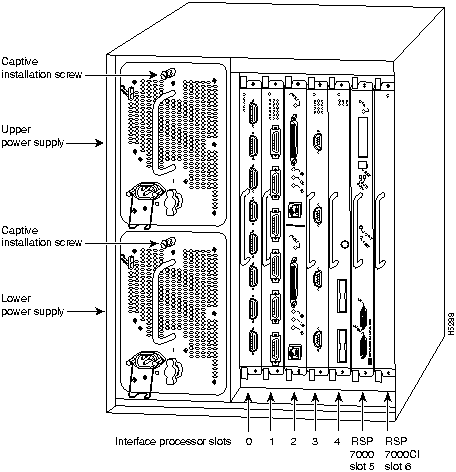
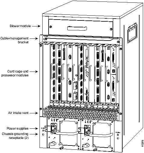
The VIP2 will operate in the Cisco 7000 series routers providing these routers have the 7000 Series Route Switch Processor (RSP7000) and 7000 Series Chassis Interface (RSP7000CI) installed. In the Cisco 7000 (see Figure 1), slots 0 through 4 are reserved for interface processors. Figure 1 shows a VIP2 in interface processor slot 2.
Figure 1 : Cisco 7000 with RSP7000 and RSP7000CI Installed, Interface Processor End
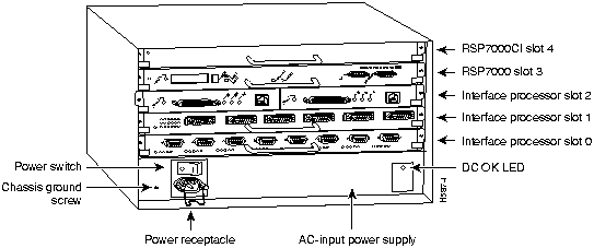
In the Cisco 7010 (see Figure 2), slots 0 through 2 are reserved for interface processors. Figure 2 shows a VIP2 in interface processor slot 2.
Figure 2 : Cisco 7010 with RSP7000 and RSP7000CI Installed, Interface Processor End
Locating the VIP2 in the Cisco 7500 Series Routers
The Cisco 7500 series consists of the Cisco 7505, Cisco 7507, and Cisco 7513 routers. The VIP2 will operate in the Cisco 7500 series routers.
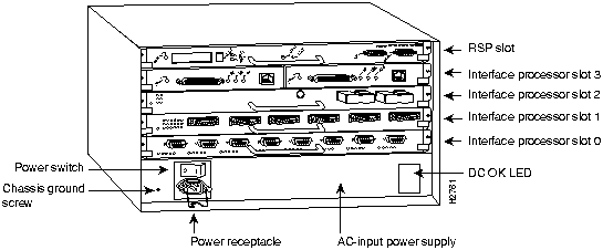
Figure 3, Figure 4, and Figure 5 show the rear of the Cisco 7500 series routers: the five-slot Cisco 7505, the seven-slot Cisco 7507, and the thirteen-slot Cisco 7513, respectively. In the Cisco 7505 (see Figure 3), slots 0 through 3 are reserved for interface processors. Figure 3 shows a VIP2 in interface processor slot 3.
Figure 3 : Cisco 7505, Interface Processor End
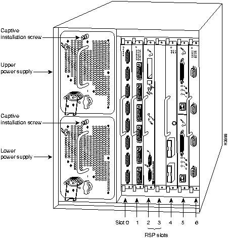
In the Cisco 7507 (see Figure 4), slots 0 and 1 and 4 through 6 are reserved for interface processors. Figure 4 shows a VIP2 in interface processor slot 5.
Figure 4 : Cisco 7507, Interface Processor End
In the Cisco 7513 (see Figure 5), slots 0 through 5 and 8 through 12 are reserved for interface processors. Figure 5 shows a VIP2 in interface processor slot 11.
Figure 5 : Cisco 7513, Interface Processor End
For complete hardware installation and maintenance information on the Cisco 7000 family routers, and the VIP2, refer to the following publications:
This section provides guidelines for when to upgrade the SRAM and DRAM on your VIP2, a list of parts and tools you will need to perform the upgrade, and it also includes safety and ESD-prevention guidelines to help you avoid injury and damage to the equipment.
SRAM and DRAM Upgrade Guidelines
Following are recommended guidelines for understanding when to upgrade DRAM and SRAM and your VIP2. For proper operation with the VIP2, we recommend that your RSP or RSP7000 has at least 24 MB of DRAM.
Table 1 : VIP2 Model Minimum Recommendations for Using DSW and DS
| VIP2 Models | Recommended for DSW | Recommended for DS |
|---|---|---|
| VIP2--10: 512 KB of SRAM and 8 MB of DRAM | No | No |
| VIP2-20: 1 MB of SRAM and 16 MB of DRAM | Yes | No |
| VIP2--40: 2 MB of SRAM and 32 MB of DRAM | Yes | Yes |
Table 2 : Recommended VIP2 Models Based on Network Size
| Number of network nodes | Less than 40,000 | Greater than 40,000 |
|---|---|---|
| VIP21 model to use | VIP2-20 | VIP2-40 |
You need the following tools and parts to upgrade a VIP2. If you need additional equipment, contact a service representative for ordering information.
Following are safety guidelines that you should follow when working with any equipment that connects to electrical power or telephone wiring.
Electrical Equipment Guidelines
Follow these basic guidelines when working with any electrical equipment:
Use the following guidelines when working with any equipment that is connected to telephone wiring or to other network cabling:
Preventing Electrostatic Discharge Damage
Electrostatic discharge (ESD) damage, which can occur when electronic cards or components are improperly handled, results in complete or intermittent failures. Port adapters and processor modules comprise printed circuit boards that are fixed in metal carriers. Electromagnetic interference (EMI) shielding and connectors are integral components of the carrier. Although the metal carrier helps to protect the board from ESD, use a preventive antistatic strap during handling.
Following are guidelines for preventing ESD damage:
![]()
Remember, the VIP2 supports online insertion and removal (OIR); therefore, you need not shut down the interface or the system power when removing a VIP2.
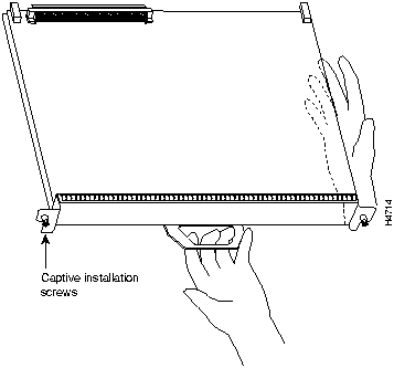
Figure 6 shows proper handling of an interface processor during installation.
Figure 6 : Handling Processor Modules for Installation and Removal (Horizontal Orientation Shown)
To remove a VIP2, follow these steps:
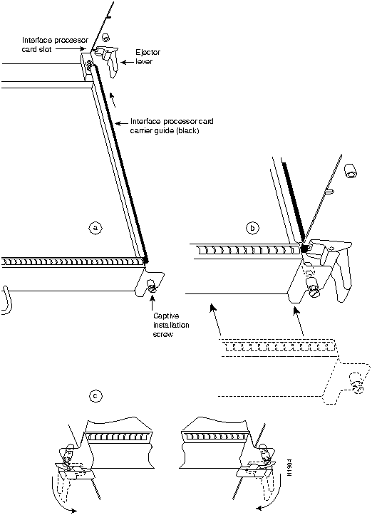
Figure 7 : Ejector Levers and Captive Installation Screws on the VIP2 (Horizontal Orientation Shown) Installing the VIP2 Memory Upgrade Kits
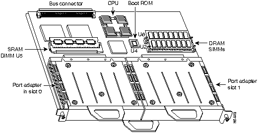
To upgrade your VIP2's memory, you must replace both the SRAM and DRAM on your VIP2. In the following procedures, refer to Figure 8 for the locations of the DRAM SIMMs and the SRAM DIMM.
The following memory kits are compatible with the VIP2-10 and VIP20:
Figure 8 : Location of DRAM SIMMs and SRAM DIMM on the VIP2-10 or VIP2-20 The DRAM on the VIP2 is contained in two single in-line memory modules (SIMMs) located in sockets U1 and U2. (See Figure 8 on page 11.) Depending on your system configuration, a memory upgrade might be required. Also, if a system problem is determined to be caused by a SIMM, a SIMM replacement might be required. Use the following procedures to replace the DRAM SIMMs on your VIP2.
Follow these steps to remove the existing DRAM SIMMs:
Figure 9 : Releasing the SIMM Spring Clips This completes the SIMM removal procedure. Proceed to the next section to install the new SIMMs.
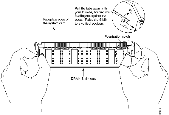
SIMMs are sensitive components that are susceptible to ESD damage. Handle SIMMs by the edges only; avoid touching the memory modules, pins, or traces (the metal fingers along the connector edge of the SIMM). (See Figure 10.)
Follow these steps to install the new SIMMs:
This completes the SIMM replacement procedure. Proceed to the section "Installing a VIP2" on page 16, to replace the VIP2 in the chassis. Refer to the section "Checking the VIP2 Upgrade," on page 17, as required
The SRAM on the VIP2 is contained in one dual in-line memory module (DIMM) located in socket U5. (See Figure 8 on page 11.) Depending on your system configuration, a memory upgrade might be required. Also, if a system problem is determined to be caused by the DIMM, a DIMM replacement might be required. Use the following procedures to replace the SRAM DIMM on your VIP2.
Follow these steps to remove the existing DIMM:
Figure 11 : Releasing the SRAM DIMM This completes the DIMM removal procedure. Proceed to the next section to install the new DIMM.
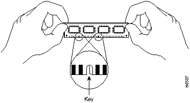
The DIMM is sensitive component that is susceptible to ESD damage. Handle the DIMM by the edges only; avoid touching the memory modules, pins, or traces (the metal fingers along the connector edge of the DIMM). (See Figure 12.)
Figure 12 : Handling an SRAM DIMM Follow these steps to install the new DIMM:
Figure 13 : Installing and SRAM DIMM in the Socket This completes the DIMM replacement procedure.
Proceed to the section "Installing a VIP2" to replace the VIP2 in the chassis; then restart the system for an installation check. Refer to the section "Checking the VIP2 Upgrade," on page 17, as required.
The VIP2 slides into the open interface processor slot and connects directly to the backplane. The interface processors are keyed to guide pins on the backplane, so the VIP2 can be installed only in an interface processor slot. Figure 7 shows the functional details of inserting an interface processor and using the ejector levers. Figure 6 shows proper handling of an interface processor during installation.
Follow these steps to install a VIP2:
The VIP2 is now properly installed in the chassis.
After you upgrade the VIP2 and reconnect cables, verify the upgrade by observing the LED states and the console display. When the system has reinitialized all interfaces, the enabled LED on the VIP2 and on all interface processors should go on. Port adapter LEDs should be on, depending on your connection. The console screen will also display a message as the system discovers each interface during its reinitialization.
If, after you have replaced SIMMs and the DIMM, the system fails to boot properly, or if the console terminal displays a checksum or memory error, check the following:
If after several attempts the system fails to restart properly, contact a service representative for assistance. Before you call, make note of any error messages, unusual LED states, or any other indications that might help solve the problem.
Verify that the VIP2 is operating properly as follows:
If an error message is displayed on the console terminal, refer to the System Error Messages publication for error message definitions. If you experience other problems that you are unable to solve, contact a service representative for assistance.
This completes the VIP2 SRAM and DRAM upgrade.
Cisco Connection Online (CCO), formerly Cisco Information Online (CIO), is Cisco Systems' primary, real-time support channel. Maintenance customers and partners can self-register on CCO to obtain additional content and services.
Available 24 hours a day, 7 days a week, CCO provides a wealth of standard and value-added services to Cisco's customers and business partners. CCO services include product information, software updates, release notes, technical tips, the Bug Navigator, configuration notes, brochures, descriptions of service offerings, and download access to public and authorized files.
CCO serves a wide variety of users through two interfaces that are updated and enhanced simultaneously---a character-based version and a multimedia version that resides on the World Wide Web (WWW). The character-based CCO supports Zmodem, Kermit, Xmodem, FTP, Internet e-mail, and fax download options, and is excellent for quick access to information over lower bandwidths. The WWW version of CCO provides richly formatted documents with photographs, figures, graphics, and video, as well as hyperlinks to related information.
You can access CCO in the following ways:
For a copy of CCO's Frequently Asked Questions (FAQ), contact
Copyright 1988-1996 © Cisco Systems Inc.
![]()
![]()

![]()
![]()
![]()

![]()
![]()

![]()
![]()
![]()
![]()
http://www.cisco.com.
cco.cisco.com.
ccohelp@cisco.com.
For additional information, contact
ccoteam@cisco.com.

tac@cisco.com.
To obtain general information about Cisco Systems, Cisco products, or upgrades, contact 800 553-6387, 408 526-7208, or
csrep@cisco.com.
![]()
![]()
![]()
![]()
![]()
![]()
![]()
![]()