|
|
Troubleshooting the Initial Hardware Configuration
Your router went through extensive testing and burn-in before leaving the factory. However, if there are problems starting up your system, follow the steps in this chapter to help identify the cause.
Sections of this chapter follow:
Use the information in this chapter to help isolate problems, or rule out the router as the problem source. If you cannot locate the source of your problem, contact a service representative for information on how to proceed in resolving the problem. Before you call, have the following information ready:
The key to problem solving in this system is to try to isolate the problem to a specific subsystem. By comparing what the system is doing to what it should be doing, the task of isolating a problem is greatly simplified.
When problem solving, consider the following subsystems of the router:
Check the following items to help isolate the problem:
Check for the following symptoms to help isolate the problem:
If the router is operating at an abnormally high temperature, the following message will be transmitted to the console screen:
%SYS-1-OVERTEMP: System detected OVERTEMPERATURE condition. Please resolve cooling
problem immediately!
Typical causes of abnormally high system temperature follow:
The router's front panel has LED indicators for determining system performance and operation at a glance. The following sections contain information on reading the LED indicators.
Figure 4-1 shows the network activity and health indicators and the run and power lights on the router front panel.
Figure 4-1 Cisco 4000 Series---Front Panel Indicators

From left to right, when facing the chassis front, the three lower LEDs on the left correspond in position to the three network processor modules, if present, and represent their status. The upper LEDs, when blinking, indicate network activity on their respective interfaces.
When on, the bottom LED on the far right indicates that the system card's power is on, and the top LED on the far right indicates that the processor is working.
The network processor module LEDs are all visible through cutouts in the rear of the chassis.
When facing the rear of the chassis, the LEDs on the dual-port Ethernet network processor module are labeled as shown in Figure 4-2. (Also see Figure 2-9.)
Figure 4-2 Dual-Port Ethernet Network Processor Module LEDs

When facing the rear of the chassis, the LEDs on the single-port Ethernet network processor module are labeled as shown in Figure 4-3. (Also see Figure 2-5.)
Figure 4-3 Single-Port Ethernet Network Processor Module LEDs

Descriptions of the Ethernet LED indicators follow:
The two LEDs in the Token Ring network processor module are labeled 16M and IN-RING. (See Figure 4-4.)
Figure 4-4 Token Ring Module Network Connector
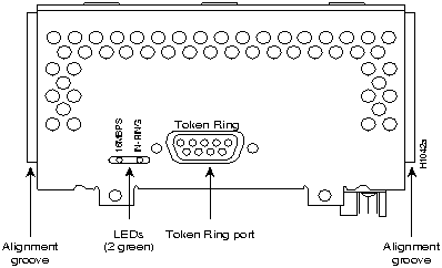
The left LED (16M) indicates ring speed. When lit, it indicates a ring speed of 16 Mbps; when not lit, it indicates a ring speed of 4 Mbps.
The right LED (In-Ring), when lit, indicates that the network processor module is inserted into the ring. If it is not lit, the network processor module is not inserted into the ring.
![]()
The four port serial network processor module has six LEDs per port. (See Figure 4-5 and Figure 4-6.) LED Indicators and colors are explained in Table 4-1. The four port serial LEDs functions are different from the dual serial module's functions.
Figure 4-5 Four-Port Serial Network Processor Module Ports
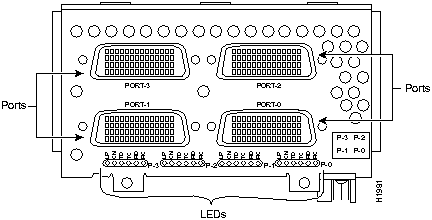
Figure 4-6 G.703/G.704 Serial Network Processor Module Ports (DB-15)
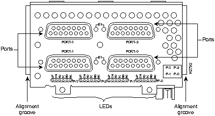
Table 4-1 Four Port Serial Network Processor Module LED Indicators
| LED Labels and Colors | Indication |
|---|---|
| LP (yellow) | Loop |
| CN (green) | Connect (DSR, DTR, DCD, RTS, CTS) |
| TD (green) | Transmit data |
| TC (green) | Transmit clock |
| RD (green) | Receive data |
| RC (green) | Receive clock |
TC, RC, TD, and RD are on only when the associated line is changing state; if a line is stuck high or low, the LED is off.
The names of the LEDs are given according to standard serial interface naming conventions. For example, TD (transmit data) is always associated with the data that is driven by the DTE regardless of whether the port on the four port serial module is a DTE or a DCE. This means that TD reflects output data when the port is a DTE and input data when the port is a DCE. RD (receive data) is controlled in a similar way. TC (transmit clock) and RC (receive clock) are always associated with the clocks that are driven by the DCE: outputs for a DCE port and inputs for a DTE.
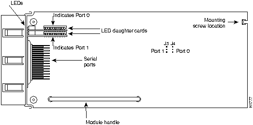
The dual serial network processor module has two LED cards. As viewed from the front (see Figure 4-7), the left card is marked P-0 (for port 0), and the right card is marked P1 (for port 1). The lower serial port is port 0, and the upper serial port is port 1, as shown on the labels. There are 10 LEDs per port. System network processor modules can be configured for either DTE or DCE.
Figure 4-7 Serial Port Labeled V2
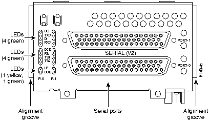
Figure 4-8 shows the top view of the dual serial network processor module. Note the locations of the LED daughter cards and the ports that they indicate.
Figure 4-8 Dual Serial Network Processor Module---Top View
When DCE cables are used and when the port is configured in software with the clockrate command as a DCE port, the bottom LED will light. (See Figure 4-9.) (For a further explanation of the clockrate command, see the appropriate Cisco IOS software publication.)
Figure 4-9 shows the dual serial port network processor module LED card.
Figure 4-9 Dual Serial Port LED Card---Side View
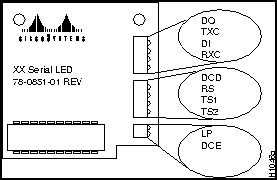
The convention used here to indicate corresponding signals for DTE/DCE is to list DTE first. For example, Figure 4-9 shows the top LED, D0, indicates TXD in DTE mode or RXD in DCE mode.
The dual serial port network processor module LED Indicators are explained in Table 4-2.
Table 4-2 Dual Serial Network Processor Module LED Indicators
| Serial LED Card Outer Labels | Indication (DTE/DCE) |
|---|---|
| DO | Data Out (TXD/RXD) |
| TXC | Transmit Clock |
| DI | Data In (RXD/TXD) |
| RXC | Receive Clock |
| DCD | Data Carrier Detect |
| RS | Receive Signaling |
| TS1 | Transmit Signaling |
| TS2 | Transmit Signaling |
| LP | Loop |
| DCE | Lit if network processor module is DCE |
Dual-attachment FDDI network processor modules have one LED per port, located adjacent to the corresponding port on the module panel (see Figure 4-10 and Figure 4-11), while single-attachment modules have one LED, located adjacent to the single port on the module panel. (See Figure 4-12.)
Figure 4-10 Dual-Attachment Single-Mode FDDI Module---End View
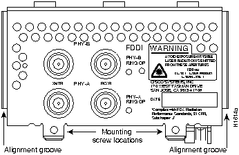
Figure 4-11 Dual-Attachment Multimode FDDI Module---End View
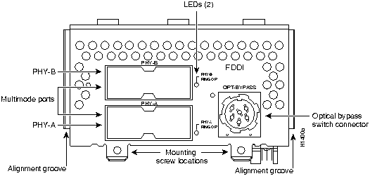
Figure 4-12 Single-Attachment Multimode FDDI Module---End View
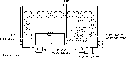
When lit, a module LED indicates a ring up condition. Dual-attachment FDDI module LEDs indicate which PHY on the network processor module is inserted into the ring; if a PHY is not actively inserted into the ring, the LED is not lit. On a single-attachment module, the LED indicates ring up when lit; when the LED is not lit, it indicates that the module is not inserted into a ring.
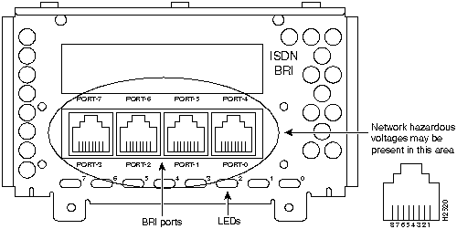
When on, the multiport BRI network processor module status LEDs indicate a Layer 1 connection on the corresponding port. When off, the LEDs indicate that the link is not established on the corresponding port.
Figure 4-13 Eight-Port BRI Network Processor Module
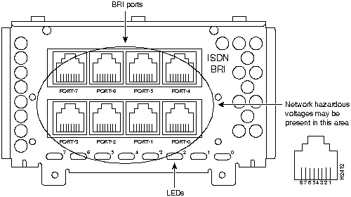
Figure 4-14 Four-Port BRI Network Processor Module
The three LEDs on the CT1 network processor module are labeled loopback, local alarm, and remote alarm. (See Figure 4-15.)
Figure 4-15 Channelized T1 Network Interface Processor
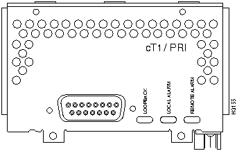
The three LEDs on the CT1 front panel indicate the following:
The three LEDs on the CE1 network processor module are labeled loopback, local alarm, and remote alarm. (See Figure 4-16.)
Figure 4-16 Channelized E1 Network Interface Processor
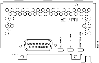
The three LEDs on the CE1 front panel indicate the following:
The three LEDs on the ATM network processor module are labeled loopback, local alarm, and remote alarm. (See Figure 4-17 and Figure 4-18.)
Figure 4-17 ATM Network Processor Module with STS-3c/STM-1 Single Mode PLIM
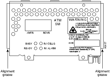
Figure 4-18 ATM Network Processor Module with STS-3c/STM-1 Multimode PLIM
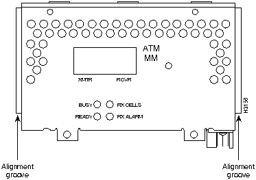
Four LEDs on the ATM front panel indicate the following:
|
|
Copyright 1988-1995 © Cisco Systems Inc.