|
|
This chapter describes the tasks you must perform to install your system. Sections of this chapter follow:
The router ships with optional rubber "feet." For a desktop or wall-mounted chassis, install the feet to provide adequate spacing between the chassis and the supporting surface for proper ventilation. For a rack-mounted chassis, do not install the rubber feet if the chassis is to be mounted directly above another chassis in the same rack.
The router system has three mounting options: standard 19-inch rack mount, telco rack mount, or wall mount. The procedures for the different mounting options involve removing the front panel and component tray from the chassis shell and then installing the empty shell in position before reinserting the component tray.
The optional rack-mount/wall-mount kit ships with its own set of instructions for rack and wall mounting. If you are planning to rack-mount or wall-mount the router, do so before making the network and power connections while following the procedures described in the separate rackmount/wall-mount publication included with the rack-mount kit.
To prepare for initial startup and configuration, you must connect an EIA/TIA-232 cable between an ASCII terminal and the system console port, and you must attach the power cord. The console port and auxiliary ports have jackscrews to accommodate cables with thumbscrews. If your cable connection requires it, the jackscrews can be removed.
Follow these steps to connect your system's console port to a terminal:
Make the network connections by attaching the network interface cables to the appropriate connector on the network processor modules.
If more than one network processor module of a given interface type is used in a system, the lowest unit number of a given interface type is the module closest to the power supply. (See the sections "Slot Numbering" and "Unit Numbering" in the chapter "Preparing for Installation.")
Figure 3-1 Making Token Ring Connections
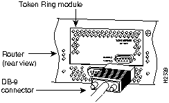
When all the network connections are complete, proceed to the section "Making Final Connections to the Router."
Ethernet network processor modules contain both Ethernet AUI connectors and 10BaseT connectors. Dual Ethernet modules contain two of each type of connector interface.
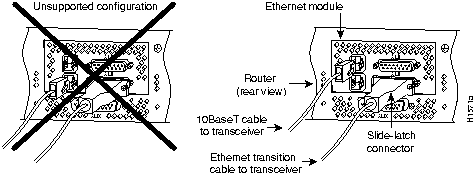
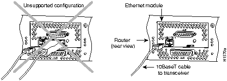
For dual-port Ethernet modules (see Figure 3-2), connect either the Ethernet AUI connector or the 10BaseT connector on a specific Ethernet port, but not both connectors on the same port. For singleport Ethernet modules (see Figure 3-3), connect either the Ethernet AUI or the 10BaseT connector, but not both on the same module.
In Figure 3-2, the configuration on the left, showing two network connections attached to Port 0, is unsupported; the configuration on the right, which shows two network connections, one to Port 0 and one to Port 1, is supported.
Figure 3-2 Making Dual-Ethernet Module Network Connections
In Figure 3-3, the single-port Ethernet module on the left shows an unsupported configuration of two network connections going to two connectors on the same port; the module on the right shows a supported connection with a single 10BaseT cable connecting to a single connector on the port.
Figure 3-3 Unsupported and Supported Single-Port Ethernet Module Connections
Follow these steps to make your AUI connections.
When all your network connections are complete, proceed to the section later in this chapter, "Making Final Connections to the Router."
Follow these steps to make your 10BaseT connections.
When all your network connections are complete, proceed to the section later in this chapter, "Making Final Connections to the Router."
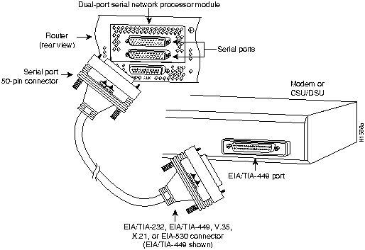
The 60-pin DB-60 connector is standard on the four-port serial network processor module; the 50-pin DB-50 connector is standard on the dual serial network processor modules. Use the specific serial transition cable for the module type and the correct EIA/TIA standard connector for your modem or channel service unit/digital service unit (CSU/DSU) connector type.
![]()
Figure 3-4 60-Pin Four-Port Serial Cable Connections

Follow these steps to make your serial connections.
Figure 3-5 Making Serial Connections to the Four-Port Serial Module
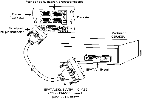
Figure 3-6 Making Serial Connections to the Dual Serial Module
![]()
When all your network connections are complete, proceed to the section later in this chapter, "Making Final Connections to the Router."
Using the appropriate cable (see the following section, "BRI Cable Specifications"), connect the Basic Rate Interface (BRI) port to the Integrated Services Digital Network (ISDN) through the NT1. The common carrier will provide the NT1 connection worldwide, except in North America, where the NT1 is customer owned. The NT1 is an ISDN channel service unit/digital service unit (CSU/DSU).
![]()
The BRI network processor module supports pointtopoint operation at OSI Layer 1. Only one source (the transmitter) and one sink (the receiver) are actively transmitting at any time in each direction at an S interface (CCITT specification I.430 section 3.1). The BRI module does not support a pointtomultipoint wiring configuration. Because the BRI module does not support pointtomultipoint configuration, D-channel access procedures are not implemented.
The specifications for the BRI cable are given in Table 3-1.
Table 3-1 BRI Cable Specifications
| Parameter | High-Capacitance Cable | Low-Capacitance Cable |
|---|---|---|
| Resistance (@ 96 kHz(1)) | 160 ohms/km | 160 ohms/km |
| Capacitance (@ 1 kHz) | 120 nF/km(2) | 30 nF/km |
| Impedance (@ 96 kHz) | 75 ohms | 150 ohms |
| Wire diameter | 0.024" (0.6 mm) | 0.024" (0.6 mm) |
| Distance limitation | 32.8' (10 m) | 32.8' (10 m) |
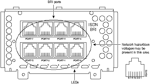
The BRI network processor module (see Figure 3-7 and Figure 3-8) supports eight BRI ports. Each BRI port is an RJ-45 8-pin connector. Use an appropriate cable to connect the BRI module directly to an Integrated Services Digital Network (ISDN) through an ISDN channel service unit/digital service unit (CSU/DSU) called the NT1. The common carrier will provide the NT1 connection, except in North America, where the NT1 is customer owned.
![]()
Figure 3-7 Four-Port BRI Network Processor Module
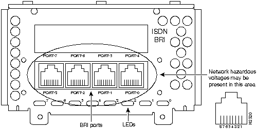
Figure 3-8 Eight-Port BRI Network Processor Module
The BRI interface port pinout is shown in Table 3-2.
Table 3-2 BRI Port Pinout (RJ-45)
| 8 Pin(1) | TE(2) | NT(3) | Polarity |
|---|---|---|---|
| 3 | Transmit | Receive | + |
| 4 | Receive | Transmit | + |
| 5 | Receive | Transmit | -- |
| 6 | Transmit | Receive | -- |
![]()
An external loopback RJ-45 connector, useful for isolating hardware problems on an individual BRI port, can be constructed as follows:
With the loopback RJ-45 connector plug installed in a BRI port, use the test interface command to determine that the hardware is functioning correctly.
When on, the multiport BRI network processor module status LEDs indicate a Layer 1 connection on the corresponding port. When not on, the LEDs indicate that the link is not established on the corresponding port.
The Cisco Systems Basic Rate Interface (BRI) network processor module is a processor/interface card assembly for use within a range of data communication (gateway and router) chassis supplied by Cisco Systems throughout Europe. The BRI module is a self-contained product that provides all of the hardware necessary to allow connection of Cisco Systems' chassis to either four or eight Basic Access Integrated Switched Digital Networks (ISDN), each at the S reference point. The ISDN usage is restricted to the point-to-point mode only.
The BRI network processor module must have a dedicated S-bus connection for each of its ISDN ports. The BRI module cannot share any of its S-bus connections with other terminal equipment, therefore, no other terminals should be connected to the same S-bus as a BRI module connection.
The four or eight ISDN connections must be made to network connection points that are provided by one network vendor or public telecom operator (PTO) to ensure that common network timing exists between the ISDN ports used. Failure to observe this point may result in lost (nonrecoverable) data packets due to timing slips.
The BRI network processor module is fully transportable between compatible host chassis. The choice of each compatible chassis has no effect on the capabilities, functionality, or performance of the BRI network processor module.
The BRI network processor module consists of the following subassemblies:
The BRI network processor module provides users of compatible host routers or bridge chassis with a high-speed throughput, point-to-point connection that can be set up over the digital telecommunication network ISDN.
Read the following sections before connecting the BRI port of your router to a network.
Where your PTO has provided you with ISDN modular sockets, the BRI module can be plugged in to make the connection. Connections should only be made to a BRI module properly installed within the host chassis.
![]()
In certain countries, the BRI network processor module must be hardwired permanently to the Sreference connection point (your Cisco Systems dealer will advise). This is accommodated for by the use of a connect one-timeonly, nonremovable plug (RJ-45 with the latch tab removed).
The ISDN connection is regarded as a source of voltage that should be inaccessible to user contact. No attempt should be made by users to tamper with or open any PTO-provided equipment or connection hardware. Any hardwired connection (other than by a nonremovable, connect onetimeonly plug) must be made only by PTO staff or suitably trained engineers.
The BRI network processor module (four or eight port options) is approved only for installation in a host chassis and with host attachments, which are either type approved for such apparatus, or covered by a General Approval.
Except at the edge connector that plugs into the host chassis expansion slot, clearance and creepage distances of X millimeters (mm) and Y mm as listed in Table 3-3 must be maintained between the cards and other parts of the host, including any other expansion cards fitted.
Note that in Table 3-3:
Table 3-3 Creepage and Clearance Distances Based on Voltage
| Voltage Used or Generated by Other Parts of the Host or Expansion Card (Vrms or VDC)(1) | Creepage (Y mm)(2) | Clearance (X mm) |
|---|---|---|
| Up to 50 | 2.4 (3.8) | 2.0 |
| Up to 125 | 3.0 (4.8) | 2.6 |
| Up to 250 | 5.0 (8.0) | 4.0 |
| Up to 300 | 6.4 (10.0) | 4.0 |
Creepage and clearance distances are measured between adjacent parts as shown in Figure 3-9.
Figure 3-9 Creepage and Clearance Distances between BRI Module and Components
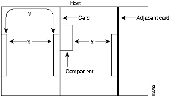
Note that in Figure 3-9, X indicates the clearance distances between cards and adjacent cards and components, and Y shows the creepage path across the surface of an insulator and between the two points indicated by X.
The power requirements of the BRI network processor module are as follows:
Ensure that the power drawn by the apparatus, together with the power drawn by any auxiliary apparatus, lies within the rating of the host chassis power supply.
The BRI network processor modules contain safety extra-low voltage (SELV) circuitry. Ensure that attachments at the interconnection ports of the apparatus are also SELV circuits. (SELV circuits are so designed and protected that, under both normal conditions and a likely fault condition, the current which can be drawn is not hazardous).
Always disconnect the host chassis from the power supply before removing any covers.
Always disconnect the host chassis from any analog telephone circuits or Basic Access ISDN (where applicable) before removing any covers.
Failure to install the BRI modules in accordance with these instructions will invalidate any telecommunication terminal equipment type approval(s).
If you have any doubt as to how to safely install the Cisco Systems BRI module correctly within a host chassis, seek advice from a qualified telecommunications engineer.
Follow these procedures to make Fiber Distributed Data Interface (FDDI) connections.
Connect a dual-attachment FDDI module as follows:
Figure 3-10 Dual-Attachment FDDI Connections
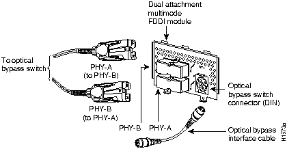
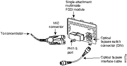
Figure 3-11 Making Single-Attachment Multimode FDDI Connections
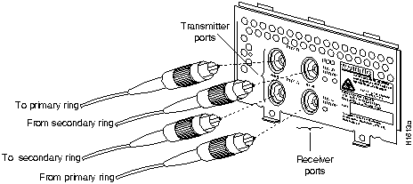
Connect a single-mode FDDI module as follows:
Figure 3-12 Single-Mode Dual-Attachment FDDI Connections
To connect the FDDI module to an external optical bypass switch (not included), use the optical bypass interface cable included with the module.
Proceed to the section "Making Final Connections to the Router" later in this chapter.
If you installed a new CT1 or if you want to change the configuration of an existing controller, you must enter the configuration mode. If you replaced the CT1 that was previously configured, the system will recognize the new CT1 and bring it up in the existing configuration.
After you verify that the new CT1 is recognized by the Cisco 4000 series, use the privileged-level configure command to configure the new CT1 module. Be prepared with the information you will need, such as the following:
The following steps describe a basic T1 configuration. Press the Return key after each configuration step.
Router# conf t

        Enter configuration commands, one per line. End with CNTL/Z. Router(config)#
Router(config)# cont t1 1
Router(config-controller)# clock source line
Router(config-controller)# framing esf
Router(config-controller)# linecode b8zs
Router(config-controller)#
%CONTROLLER-3-UPDOWN: Controller T1 1, changed state to up
Router(config-controller)#
Router(config-controller)# channel-group 0 timeslots 1,3-5,7

Router(config-controller)#

%LINEPROTO-5-UPDOWN: Line protocol on Interface Serial1:0, changed state to down
%LINEPROTO-5-UPDOWN: Line protocol on Interface Serial1:0, changed state to up
Router(config-controller)#

Router(config-controller)#
Router(config-controller)# int serial 1:0
Router(config-if)# ip address 1.1.15.1 255.255.255.0
Router(config-if)#
Router# write memory
Router# disable
Router>
Refer to the printed Router Products Configuration Guide and Router Products Command Reference publications or Cisco Connection Documentation CD-ROM for a summary of the configuration options available and additional instructions for configuring the CT1 module.
If you installed a new CE1 module or if you want to change the configuration of an existing controller, you must enter the configuration mode. If you replaced the CE1 that was previously configured, the system will recognize the new CE1 and bring it up in the existing configuration.
After you verify that the new CE1 is recognized by the Cisco 4000, use the privileged-level configure command to configure the new CE1 module. Be prepared with the information you will need, such as the following:
The following steps describe a basic E1 configuration. Press the Return key after each step.
Router# conf t

        Enter configuration commands, one per line. End with CNTL/Z. Router(config)#
Router(config)# cont e1 1
Router(config-controller)# framing crc4
Router(config-controller)# channel-group 0 timeslots 1,3-5,7

Router(config-controller)#

%LINEPROTO-5-UPDOWN: Line protocol on Interface Serial1:0, changed state to down
%LINEPROTO-5-UPDOWN: Line protocol on Interface Serial1:0, changed state to up
Router(config-controller)#

Router(config-controller)#
Router(config-controller)# int serial 1:0
Router(config-if)# ip address 1.1.15.1 255.255.255.0
Router(config-if)#
Router# write memory
Router# disable
Router>
Refer to the printed Router Products Configuration Guide and Router Products Command Reference publications or Cisco Connection Documentation CD-ROM for a summary of the configuration options available and instructions for configuring the CE1.
If you installed a new ATM interface module or if you want to change the configuration of an existing module, you must enter the configuration mode. If you replaced the ATM interface that was previously configured, the system will recognize the new interface and bring it up in the existing configuration.
After you verify that the new interface is recognized by the router, use the privileged-level configure command to configure the new ATM module. You will need the following information:
The following steps show a basic ATM configuration using just PVCs.
Router# conf t
Router(config)# int atm 0
Router(config-if)# atm sonet stm-1
Router(config-if)# ip address 1.1.1.1 255.255.255.0
Router(config-if)#         atm pvc 1 1 32 aal5snap
Router(config-if)# atm pvc 2 1 33 aal5snap
Router(config-map-list)# map-group list1
Router(config-if)# no shut
Router(config-if)#         map-list list1
Router(config-map-list)# ip 1.1.1.2 atm-vc 1 broadcast
Router(config-map-list)# ip 1.1.1.3 atm-vc 2 broadcast
Router# write memory
Router# disable
The following example shows a basic configuration using using SVCs.
Router# conf t
Router(config)# int atm 0
Router(config-if)# atm sonet stm-1
Router(config-if)# ip address 2.1.1.1 255.255.255.0
Router(config-if)# atm pvc 1 0 5 qsaal
Router(config-if)# atm nsap-address nsap-addrr
AB.CDEF.01.234567.890A.BCDE.F012.3456.7890.1234.12
Router(config-map-list)# map-group list2
Router(config-if)# no shut
Router(config-if)#         map-list list2
Router(config-map-list)# ip 2.1.1.2 nsap-addr nsap-addr  br
Router(config-map-list)# ip 2.1.1.3 nsap-addr nsap-addr  br
Router# write memory
Router# disable
![]()
If you ordered a Cisco 4000 series router with a DC-input power supply, follow the directions in this section for proper wiring.
For identification purposes, Figure 3-13 shows a Cisco 4000 series router with a DC-input power supply; Figure 3-14 shows a Cisco 4000 series router with an AC-input power supply.
Figure 3-13 Cisco 4000 Series DC-Input Power Supply---Rear View

Figure 3-14 Cisco 4000 Series AC-Input Power Supply---Rear View

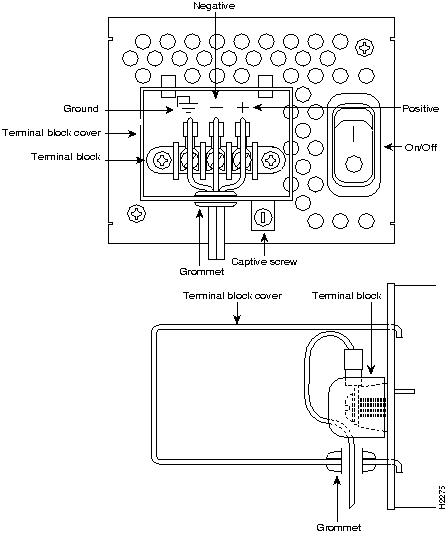
Figure 3-15 shows the Cisco 4000 DC-input power supply terminal block. Follow these procedures for wiring the terminal block.
![]()
Figure 3-15 DC-Input Power Supply Connections
![]()
![]()
This completes the procedure for wiring the DC-input power supply.
![]()
Follow this procedure to make the final connections to the router:
Your configuration can be designated with either the setup command facility or with the configuration command. For more information on software commands, refer to the appropriate software publications.
|
|
Copyright 1988-1995 © Cisco Systems Inc.