Table of Contents
Maintaining and Upgrading the Router
Maintaining and Upgrading the Router
This chapter contains information on procedures you may need to perform as your internetworking needs change.
Note If your system requires an upgrade in the future, and if new network processor modules or software replacements are necessary, an appropriate publication will be shipped to you with the parts. The publications that ship with spares and upgrades, configuration notes, do not need to be ordered separately from the new components.
This chapter contains the following sections:
Caution Before opening the router chassis, ensure that you have discharged all static electricity from your body and be sure the power is OFF. Before performing any procedures described in this chapter, review the following sections "Safety Recommendations," "General Site Requirements," "Installation Checklist," and "Required Tools and Equipment" in the chapter "Preparing for Installation."
You must open the router chassis to gain access to the router's internal components: the network processor modules, boot ROMs, and jumpers.
Refer to the section "Required Tools and Equipment" in the chapter "Preparing for Installation" for the tools needed for the following procedures.
Some Cisco 4000 series routers have a safety latch tab on the chassis that affects removing the component tray. (See Figure 5-1 and Figure 5-2.)
If you have a chassis with a safety latch tab, follow the procedure in the following section "Removing the Component Tray from a Chassis with a Safety Latch".
If you have a chassis without a safety latch tab, follow the procedure in the section "Removing the Component Tray from a Chassis without a Safety Latch" later in this chapter.

Warning Hazardous voltages may exist in or near the power supply, so use extreme caution when working near the power supply. Before starting any of these procedures, turn off power to the system, unplug the power cord, disconnect any cables at the ports, and connect your ESDpreventive wrist strap.
Follow these steps to remove the component tray from a chassis with a safety latch.
- Step 1 Turn off the system power.
- Step 2 Put on your ESD-preventive wrist strap.
- Step 3 Remove all network and power cables.
- Step 4 Loosen the (nonremovable) screw in the back of the chassis, labeled Chassis release screw in Figure 5-1.
- Step 5 Slide the component tray out of the chassis shell while facing the chassis rear panel, pulling the handle on the right side of the chassis until the safety latch catches. (See Figure 5-1.)
 Warning Before releasing the safety latch, support the component tray from underneath, either on your work surface or with your hands, to prevent personal injury. (See Figure 5-1.)
Figure 5-1 Component Tray Removal for Chassis With a Safety Latch
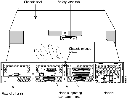
- Step 6 While supporting the component tray with one hand, push down on the safety latch tab while pulling out on the component tray.
- Step 7 Set the component tray on your work surface.

Warning Hazardous voltages may exist in or near the power supply, so use extreme caution when working near the power supply. Before starting any of these procedures, turn off power to the system, unplug the power cord, disconnect any cables at the ports, and connect your ESDpreventive wrist strap.
Follow these steps to remove the component tray from a chassis without a safety latch.
- Step 1 Turn off the system power.
- Step 2 Put on your ESD-preventive wrist strap.
- Step 3 Remove all network and power cables.
- Step 4 Loosen the (nonremovable) screw in the back of the router chassis, labeled Chassis release screw in Figure 5-2.
Figure 5-2 Component Tray Removal for Chassis Without a Safety Latch
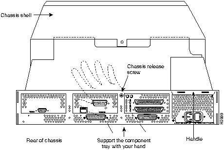

Warning Support the component tray from underneath, either on your work surface or with your hands, to prevent it from falling. (See the hand in Figure 5-2.)
- Step 5 While facing the chassis rear panel, pull the handle on the right side of the router while supporting the component tray with one hand. Slide the component tray out of the chassis shell.
- Step 6 Set the component tray on your work surface.
If you are replacing shared memory single in-line memory modules (SIMMs), you must first remove the network processor modules. Follow the steps in this section to remove a network processor module.

Caution Some network processor modules are mounted to the rear of the chassis with two external screws. On modules with external rear mounting screws, which include the Fiber Distributed Data Interface (FDDI) module, these screws must be removed before the module can be safely lifted out of the chassis, otherwise damage to the module will occur. Other types of modules may not have the two external rear mounting screws attached to the chassis.
- Step 1 With the component tray in front of you (as shown in Figure 5-3), remove the module mounting screw from the top end of the network processor module, and the two external rear mounting screws (not shown) if the module has them, and set the screws aside.
Figure 5-3 Typical Cisco 4000 Series Component Tray---Cisco 4000M Shown
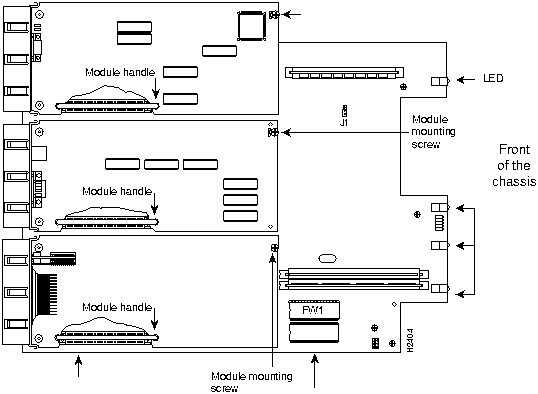
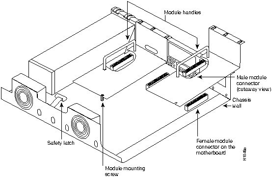
- Step 2 To lift the module out of its connector after removing the mounting screws, grasp the network processor module handle and pull straight up. (See Figure 5-4.)
 Caution Do not wiggle the handle when handling the network processor module, and do not exert any side-to-side pressure because the handle might work loose and damage the network processor module.
Figure 5-4 Network Processor Module Locations
There are two dynamic random-access memory (DRAM) systems in Cisco 4000 series routers. One is the shared memory, which is the interface that the network processor modules send data to or transmit data from, and the other is the primary or main memory, which is reserved for the CPU. In addition, the Cisco 4000M has Flash memory for storing the system software image; the Cisco 4500-M and Cisco 4700 have Flash memory for the system software image and for the boot helper image.

Caution To avoid damaging ESD-sensitive components, observe all ESD precautions. To avoid damaging the underlying system card, avoid using excessive force when you remove or replace SIMMs.
The Cisco 4000M main memory upgrade requires replacing the main memory configuration of 4 MB (one 4--MB SIMM) with one 8, 16, or 32--MB SIMM. The Cisco 4500-M main memory upgrade requires replacing the main memory configuration of 8 MB (two 4-MB SIMMs) with two 8-MB SIMMs or two 16--MB SIMMs. The Cisco 4700 main memory upgrade requires replacing the main memory configuration of 16 MB (two 8-MB SIMMs) with two 16-MB SIMMs.
For the Cisco 4000M shared memory upgrade, replace the 4--MB shared memory SIMM with a 16--MB shared memory SIMM. The Cisco 4500-M and Cisco 4700 shared memory upgrade permits you to replace the 4--MB shared memory SIMM with an 8--MB SIMM or a 16--MB SIMM.
To upgrade the Cisco 4000M Flash memory, replace the standard Flash memory configuration of 2 MB with 4 MB of Flash memory. The Cisco 4500-M and Cisco 4700 Flash memory upgrade requires replacing or adding to the standard Flash memory configuration of 4 MB with 8, 16, 32, or 64 MB of Flash memory. Figure 5-5 shows the SIMM locations in the Cisco 4000M.
Figure 5-5 Cisco 4000-M SIMM Locations
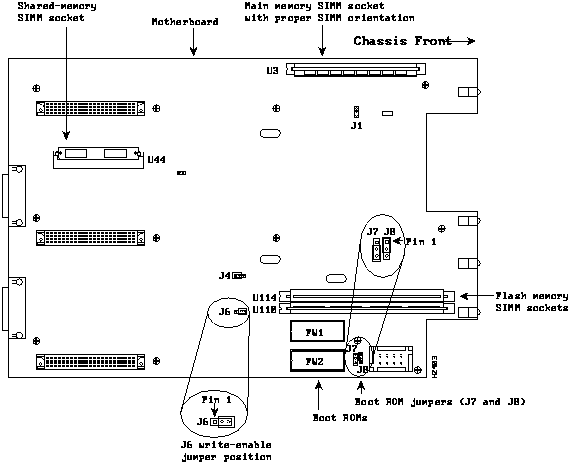
Note Jumper the Boot ROM jumpers as shown in Figure 5-5 to permit writing to Flash memory.
Figure 5-6 shows the Cisco 4500-M and Cisco 4700 SIMM and jumper locations.
Figure 5-6 Cisco 4500-M and Cisco 4700 SIMM Locations
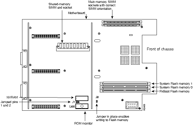
SIMMs are manufactured with a polarization notch to prevent them from being installed backward. Figure 5-7 shows the polarization notch and locations of the alignment holes on a main memory SIMM card. The main memory SIMM cards are installed with the connector edge down and the component side facing in, as shown in the upper right of Figure 5-5 and Figure 5-6.
Figure 5-7 Cisco 4000 Series Main Memory SIMM

Follow these steps to remove main memory SIMMs:
- Step 1 Put on an ESD-preventive wrist strap and ensure that it makes good contact with your skin. Connect the equipment end of the wrist strap to the metal back plate of the chassis, avoiding contact with the connectors.
- Step 2 On the motherboard, locate the main memory SIMM card sockets shown in the upper right corner of Figure 5-5 (for the Cisco 4000-M) and Figure 5-6 (for the Cisco 4500-M and Cisco 4700).
 Caution Handle SIMMs by the card edges only. SIMMs are ESD-sensitive components and can be damaged by mishandling.
- Step 3 Remove one SIMM at a time, beginning with the SIMM farthest from the edge of the motherboard. (The Cisco 4000M has only one main memory SIMM.)
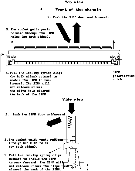
- Step 4 To lift the SIMM out of its socket, pull the locking spring clips on both sides outward and tilt the SIMM free of the clips. (See Figure 5-8.)
Figure 5-8 Removing Main Memory SIMMs
- Step 5 Hold the SIMM by the edges with your thumb and index finger and lift it out of the socket. Place the removed SIMM in an antistatic bag to protect it from ESD damage.
- Step 6 Repeat Steps 2 through 5 for each main memory SIMM card.
Proceed to the next section, "Installing Main Memory SIMMs."
Follow this procedure to install main memory SIMMs.
- Step 1 Put on an ESD-preventive wrist strap and ensure that it makes good contact with your skin. Connect the equipment end of the wrist strap to the metal back plate of the chassis, avoiding contact with the connectors.
- Step 2 On the motherboard, locate the main memory SIMM card sockets shown in the upper right corner of Figure 5-5 for the Cisco 4000-M and Figure 5-6 for the Cisco 4500-M and Cisco 4700. All of the sockets should be empty. If not, follow the steps in the section "Removing Main Memory SIMMS" earlier in this chapter.
 Caution Handle SIMMs by the card edges only. SIMMs are ESD-sensitive components and can be damaged by mishandling.
- Step 3 Hold the SIMM with the polarization notch on the right and the component side away from you with the connector edge at the bottom. (See Figure 5-7.)
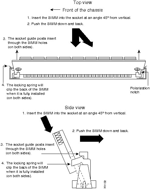
- Step 4 Beginning with the SIMM nearest the edge of the motherboard, insert the main memory SIMM card at a 45-degree angle and rock it into its vertical position (see Figure 5-9), using the minimum amount of force required. When the SIMM is properly seated, the socket guide posts will insert through the alignment holes, and the connector springs will click into place.
- Step 5 Ensure that each SIMM is straight and that the alignment holes (as shown in Figure 5-9) line up with the plastic socket guides on the socket.
Figure 5-9 Installing Main Memory SIMMs

Caution You will feel some resistance, but do not use excessive force on the SIMM and do not touch the surface components to avoid damaging them.
- Step 6 Repeat Steps 2 through 5 for each main memory SIMM.
If you are done with all SIMM replacement procedures, proceed to the section "Replacing Network Processor Modules" later in this chapter.
Follow this procedure if you are replacing the shared-memory SIMMs:
- Step 1 Unplug the chassis power cord and network connections.
- Step 2 Put on an ESD-preventive wrist strap and ensure that it makes good contact with your skin. Connect the equipment end of the wrist strap to the metal back plate of the chassis, avoiding contact with the connectors.
- Step 3 Remove the chassis cover as described in the section "Accessing the Router Internal Components" earlier in this chapter.
- Step 4 Remove and safely store all the network processor modules present as described in "Removing Network Processor Modules"earlier in this chapter for later reinstallation.
- Step 5 Locate the shared-memory SIMM card socket shown on the left of the motherboard as shown in Figure 5-5 (for the Cisco 4000-M) and Figure 5-6 (for the Cisco 4500-M and Cisco 4700).
- Step 6 Turn the chassis so that the rear of the chassis is closest to you.
- Step 7 The SIMMs are held in place at each end by small metal spring clasps. To remove a shared memory SIMM, push the two metal clasps apart. Angle the SIMM upward and pull it out. (See Figure 5-9.)
 Caution Do not exert pressure on the components on the SIMM surface because it might damage them. The sides of the SIMM must clear the metal clasps before the SIMM can be safely removed.
- Step 8 Place the removed SIMM in an antistatic bag to protect it from ESD damage.
- Step 9 Repeat Steps 7 and 8 for each SIMM.
- Step 10 Proceed to the next section, "Inserting Shared-Memory SIMMs."
Follow this procedure to insert shared-memory SIMMs:
- Step 1 Unplug the chassis power cord and network connections.
- Step 2 Put on an ESD-preventive wrist strap and ensure that it makes good contact with your skin. Connect the equipment end of the wrist strap to the metal back plate of the chassis, avoiding contact with the connectors.
- Step 3 Remove the chassis cover as described in the section "Accessing the Router Internal Components" earlier in this chapter.
- Step 4 On the left of the motherboard (as aligned in Figure 5-5 and Figure 5-6), find the shared-memory SIMM card socket locations. All the sockets should be empty. If not, remove the shared-memory SIMMs following the procedures in the section "Replacing Shared-Memory SIMMs" earlier in this chapter.
- Step 5 Turn the chassis so that the side with the shared-memory SIMM cards is closest to you.
 Caution Handle SIMMs by the card edges only. SIMMs are sensitive components and can be shorted by mishandling.
- Step 6 Hold the SIMM with the connector edge at the bottom, component side facing you, and the polarization notch on the left. (See Figure 5-10.)
Figure 5-10 Inserting Shared-Memory SIMMs
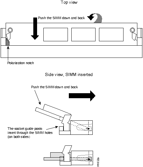
- Step 7 To insert a SIMM, angle it into position, then carefully push down and back on the edges, holding each edge so that it securely snaps in place. (See Figure 5-10.) When it snaps into place, the two metal holders clip over the edge of the SIMM, and it sits horizontally.
 Caution Avoid damage to the SIMMs and SIMM socket by not handling them roughly. The SIMMs are also sensitive to ESD damage.
- Step 8 Check that the SIMM is straight and that the holes are aligned with the socket guide posts on the socket. (See Figure 5-10.)
If you are done with all SIMM replacement procedures, proceed to the section "Replacing Network Processor Modules" earlier in this chapter.
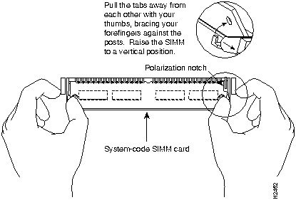
The boot helper image (Rxboot image) is stored in Flash memory on the Cisco 4500-M and Cisco 4700. Take the following steps to replace the 4-MB SIMM with an 8--MB or 16-MB SIMM. (See Figure 5-11.)
Figure 5-11 Removing the Boot Helper Flash Memory SIMM
- Step 1 Put on an ESD-preventive wrist strap and ensure that it makes good contact with your skin. Connect the equipment end of the wrist strap to the metal back plate of the chassis, avoiding contact with the connectors.
- Step 2 On the lower right corner of the Cisco 4500-M and Cisco 4700 motherboard, locate the SIMM card socket marked RxBoot Flash memory. (See Figure 5-6.)
 Caution Handle SIMMs by the card edges only. SIMMs are ESD-sensitive components and can be damaged by mishandling.
- Step 3 To lift the SIMM out of its socket, pull the locking spring clips on both sides outward and tilt the SIMM free of the clips. (See Figure 5-11.)
Proceed to the section "Installing Flash-Memory SIMMs."
You upgrade boot helper Flash memory by replacing the existing SIMM (labeled System Flash Memory 0), or by adding a second SIMM to the empty socket (labeled System Flash Memory 1).
Take the following steps to add Flash-memory SIMMs:
- Step 1 On the motherboard, locate the Flash-memory SIMM sockets shown in Figure 5-5 and Figure 5-6.
 Caution Handle SIMMs by the edges only. SIMMs are ESD-sensitive components and can be damaged by mishandling.
- Step 2 Hold the SIMM with the polarization notch on the right and the component side away from you with the connector edge at the bottom.
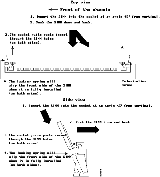
- Step 3 Referring to Figure 5-12, insert the Flash-memory SIMM at a 45-degree angle and rock it into its vertical position. (See Figure 5-5 and Figure 5-6.) When the SIMM is properly seated, the socket guide posts will insert through the alignment holes, and the locking springs will click into place. Use the minimum amount of force required.
Figure 5-12 Inserting Flash-Memory SIMMs

Caution You will feel some resistance, but do not use excessive force on the SIMM and do not touch the surface components to avoid damaging them.
- Step 4 Check the alignment of each SIMM to make sure that it is straight and that the alignment holes are lined up with the plastic socket guides.
If you have completed all memory upgrade procedures, proceed to the section "Replacing Network Processor Modules" later in this chapter.
To upgrade the boot read-only memory (ROM) software to a new software image, the existing boot ROMs must be replaced.
- Step 1 Open the chassis and expose the boot ROMs following the procedures in the section "Accessing the Router Internal Components" earlier in this chapter.
- Step 2 After the boot ROMs (FW1 and FW2) on the system card are exposed (see Figure 5-5), follow the procedures in this section to replace the ROMs.
Note It is not necessary to remove the Flash EPROM card for this upgrade procedure.
 Caution The correct placement of the boot ROMs is crucial. If improperly positioned, the new components could be damaged when the system is powered on. Read all of the instructions before proceeding. To prevent damage to the ROMs from ESD (when handling the system and its components), follow the ESD procedures described earlier. Also, be careful not to damage or scratch the printed circuit card under the ROMs.
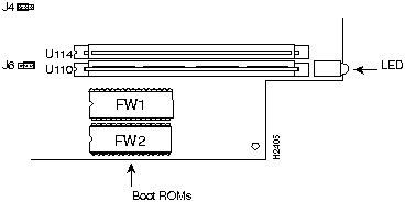
- Step 3 Locate the boot ROMs, FW1 and FW2, on the motherboard. (See Figure 5-13.)
Figure 5-13 Boot ROMs Locations
- Step 4 Gently extract the old ROM with an ROM extraction tool or a small flat-blade screwdriver, and set the old boot ROM aside.
- Step 5 Insert the new boot ROMs in their respective sockets in the orientation shown in Figure 5-13, being careful not to bend or crush any of the bottom pins. To straighten out a bent pin, use needlenose pliers. Align the notch in the new ROM with the notch in the ROM socket, ignoring the orientation of the label.
 Caution The notch on the ROM must match the notch on the socket on the card. Installing the components backward will damage them.
Proceed to the next section, "Replacing Network Processor Modules."
Follow these steps to replace a network processor module:
- Step 1 Hold the network processor module by its handle, align it with the grooves in the chassis (not shown) and over its connector, and push it lightly against the chassis wall. (See Figure 5-4.)
- Step 2 Gently, without bending the connector pins, push the network processor module into place, inserting the male network processor module connector into the female network processor module connector on the motherboard.
- Step 3 Replace the module mounting screw on the end of the network processor module. (See Figure 5-4.)
- Step 4 If the module has external rear mounting screws to attach the network processor module to the rear of the chassis, replace the screws at this time.
 Caution Do not overtorque the module mounting screw. The network processor module or the underlying motherboard could be damaged. The maximum screw torque is 7 inch-lb.
Follow these steps to replace the component tray in the chassis shell:
- Step 1 Reinsert the component tray into the shell, pushing on the back of the tray, while at the same time pressing on the chassis release screw (as shown in Figure 5-1) with the thumb of your right hand.
- Step 2 Retighten the chassis release screw.
Test your installation by rebooting the system. When you power up a system in which one or more of the boot ROMs was incorrectly inserted, the system will not boot into the ROM monitor or the operating system mode.
If you suspect that your boot ROMs were inserted incorrectly, reopen the chassis, locate the affected boot ROM and remove it, straighten its pins, reinsert the boot ROM, and try booting again.
Note To recover a lost password if Break is disabled on the router, it is necessary to have physical access to the router.
To recover a lost password, follow this procedure.
- Step 1 Attach an EIA/TIA-232 ASCII terminal to the router console port, which is located at the rear of the router.
- Step 2 Configure the terminal to operate at 9600 baud, 8 data bits, no parity, 1 stop bit (or to whatever settings the router is set).
- Step 3 Enter the command show version to display the existing configuration register value. Note this value for later use in Step 13.
- Step 4 If Break is disabled, power cycle the router. (Turn the router off, wait 5 seconds, and then turn it on again.) If Break is enabled on the router, send a Break and then proceed to Step 5.
- Step 5 Within 60 seconds of turning the router on, press the Break key. This action causes the terminal to display the bootstrap program prompt (> for the Cisco 4000-M and rommon > for the Cisco 4500-M and Cisco 4700).
- Step 6 To reset the configuration register to boot from the boot ROMs for the Cisco 4000M, enter o/r at the bootstrap prompt as follows:
> o/r
- To reset the configuration register to boot from the boot ROMs for the Cisco 4500-M and Cisco 4700, enter confreg 0x141, as follows:
rommon > confreg 0x141
- Step 7 Initialize the router by entering the i command as follows:
> i
- The router will reset, the configuration register is set to 0x141, and the router will execute the boot ROM system image and prompt you with the system configuration dialog as follows:
--- System Configuration Dialog ---
- Step 8 Enter no to the system configuration dialog prompts until the following system message displays:
Press RETURN to get started!
- Step 9 Press Return. The boot ROM prompt appears as follows:
Router(boot)>
- Step 10 Enter the enable command to enter the EXEC mode in the boot ROM image. The prompt changes to the following:
Router(boot)#
- Step 11 Enter the show configuration EXEC command to display the enable password in the router's configuration file.
- Step 12 Enter the configure terminal command at the EXEC prompt. You are prompted as follows:
Router(boot)# conf
Configuring from terminal, memory, or network [terminal]? <Return>
Enter configuration commands, one per line.
Edit with DELETE, CTRL/W, and CTRL/U; end with CTRL/Z
- Step 13 Using the config-reg 0xvalue command, change the configuration register value back to its original value (from Step 3), or change it to a value of 0x102, which in the absence of a boot system command in the configuration file causes the router to boot from Flash memory and to ignore Break.
- Step 14 Exit configuration mode by entering Ctrl-Z.
- Step 15 Reboot and enable the router using the recovered password.
Copyright 1988-1995
©
Cisco Systems Inc.
![]()
![]()
![]()

![]()

![]()
![]()

![]()

![]()


![]()

![]()

![]()
![]()
![]()

![]()

![]()
![]()

![]()
![]()

![]()
![]()