This chapter focuses on a series of connectivity problems associated with routing and bridging in IBM-based networks, possible causes of those symptoms, and general suggestions for identifying, isolating, and resolving those causes.
Note This chapter focuses on IBM-related and Token Ring problems. General diagnostic tools and techniques used for isolating serial line problems are discussed in the "Troubleshooting Serial Line Problems" chapter.
Concurrent Routing and SRB Connectivity Scenario
With multiprotocol internetworks, the chances of misconfiguration resulting in connectivity loss are substantially greater than with single-protocol networking environments. Along with the added efficiency and flexibility of multiprotocol internetworks comes an added level of management complexity.
The following connectivity-related scenario features both Novell and Sun networking systems sharing access to resources over Token Ring and serial media. This scenario illustrates problems facing internetworks characterized by concurrent bridging and routing.
Symptoms
Consider a corporate network composed of Token Ring segments partitioned with source-route bridges (SRBs) as illustrated in Figure 8-1. Here, the personal computers (PCs) on Ring 4 are unable to connect to Novell servers on Rings 2 and 3, while a PC on Ring 3 cannot communicate with the Sun file server on Ring 4.
Environment Description
Figure 8-1 illustrates a map of the environment discussed in this case.
Figure 8-1 : Initial SRB Problem Environment
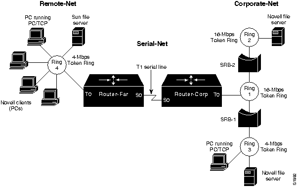
The following summarizes the relevant elements of this internetworking environment:
- The primary corporate network (Corporate-Net) consists of one 4-Mbps and two 16-Mbps Token Rings separated by non-Cisco SRBs (SRB-1 and SRB-2).
- Users on the 4-Mbps Token Ring at a remote sales office (Remote-Net) are linked to the Corporate-Net over a T1 service (Serial-Net), with routers (Router-Corp and Router-Far) providing routing service for both TCP/IP and Novell IPX traffic between Corporate-Net and Remote-Net.
- The LANs are all IEEE 802.5 Token Rings.
- The network applications running over the WAN include X Windows, file transfer, mail, Novell NetWare file service, and virtual terminal connections.
Diagnosing and Isolating Problem Causes
Given the situation, the following possible problems are the most likely candidates for interconnection failure:
- Missing multiring interface configuration command
- Misconfigured IP network addresses
- No source-route bridging driver on a Novell server
- Software bug on some network device
The next step is to eliminate each potential cause as the problem source and then test the network to determine whether it is operational. The following discussion works through the process of problem isolation.
Finding Missing multiring Commands
Given the difficulties being experienced, router configuration problems are definite possibilities. In particular, if routed protocols are not making their way through an SRB environment, look for missing multiring interface configuration commands. The following steps outline actions to diagnose and remedy potential configuration problems in this kind of environment.
Step 1 Use the write terminal command on the two routers connected to the T1 serial line to look for a multiring interface configuration command for each routed protocol, or use the all keyword option (applied to the Token Ring interfaces). Note that the multiring command is only required when there are other SRB bridges on the LAN. Excessive use of multiring can lead to other problems.
Step 2 Assuming that the multiring command is not included or that it does not cover a particular protocol that is being routed and subsequently bridged as in this scenario, make any required changes. Figure 8-2 illustrates a specification of the multiring command that generates RIFs for IP frames, but not for Novell IPX frames. Refer to the Router Products Configuration Guide and Router Products Command Reference publications for more information about using the multiring command.
Figure 8-2 : Example of Using the multiring Command

Looking for a Misconfigured IP Address
The specification of IP network addresses is often the source of connectivity problems. An incorrect IP address can create a discontinuous network space, which results in a complete stoppage of all IP traffic at the point of discontinuity.
In this scenario, assume that Token Rings 1, 2, 3, and 4 are all configured for major net 131.108.0.0. The interfaces attached to the serial line linking the two sites are assigned IP addresses 192.1.100.1 (Router-Far) and 192.1.100.2 (Router-Corp). The discontinuity in this example results from the separation of segments in the same subnet (the four Token Rings) by a segment that belongs to a different major network (the serial network).
Step 1 Use the write terminal EXEC command to determine the address specifications associated with the Token Rings and serial lines to which the routers are attached.
Step 2 There are two solutions for this situation:
- Reconfigure the IP address assignments for the serial lines so that both interfaces attached to the link belong to the same major network as the Token Rings.
- Assign different network numbers to all three networks (Remote-Net, Serial-Net, and Corporate-Net).
Note For more information about assigning IP addresses and using subnet addressing, refer to the Router Products Configuration Guide and Router Products Command Reference publications.
Checking the End Systems
The end systems (PCs) attached to the various rings are another likely problem source in this scenario. The following steps outline actions to diagnose and remedy potential problems associated with the end systems in this kind of environment.
Step 1 Check the end systems for SRB drivers. Missing drivers might make end systems unable to participate in protocol exchanges.
Step 2 Reconfigure the end systems or replace them with systems that have the ability to handle SRB.
Step 3 In addition to missing SRB drivers, end systems may be unable to participate in protocol exchanges because of software problems. To isolate this problem in a TCP/IP environment, ping the end systems.
Step 4 If there is no response, the hardware address might be present. If so, the device was previously seen; if not, it was either never seen, or the entry timed out. Use the show rif and show arp EXEC commands to determine the hardware address of the end systems in the ARP and RIF tables. Figure 8-3 and Figure 8-4 illustrate the output of the show rif and show arp commands.
Figure 8-3 : show rif EXEC Command Output
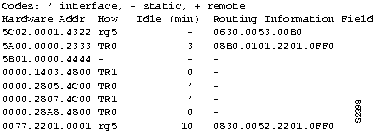
Figure 8-4 : show arp EXEC Command Output

Step 5 If the end system does not appear in the table, use the clear rif-cache and clear arp-cache commands. Be aware, however, that clearing caches causes network activity spikes while the caches are repopulated. If this high activity contributes to station problems, this might produce random results, which may be confusing to a user doing a "sample of one on a random result"---in other words, the station response gets lost and the user assumes it is still unavailable. Set the RIF timeout to a small value and ping the end system at intervals greater than the RIF timeout to see if the end system can respond.
Step 6 If the end system does not respond, use a network analyzer to look for the response of the end system to the Exchange ID (XID)-to-NULL SAP packet (DSAP value of 00) from the router.
- The default timeout for Address Resolution Protocol (ARP) table entries is much larger than the Routing Information Field (RIF) entries (such as 4 hours for ARP and 15 minutes for RIF). The first time that a station is pinged, there are no ARP or RIF table entries for its hardware address, so both entries are updated with the ARP response from the end system. After the default timeout for RIF, the RIF entry is cleared, whereas the ARP entry remains. When this situation arises, if the end system is pinged again, the router generates an XID packet and sends it to the destination hardware address of the end system with a NULL SAP value (DSAP value of 00) to find the RIF.
Step 7 If you do see the router XID-to-NULL SAP packet, but the end system is unable to respond, there is probably a problem with the end system (host) SRB software, and you must upgrade the software on the end system.
- (In one case, there was a bug in the IBM RS6000 where an RS6000 would not reply to an XID sent with a NULL SAP value.)
Note If an end system does not respond to the XID-to-NULL SAP packet (DSAP value of 00), and you are unable to upgrade its software, make the ARP time-out on the end system a little less than the RIF timeout. This setting causes the RIF and ARP to time out at about the same time and forces the routers to send an ARP instead of a XID-to-NULL SAP packet.
Resolving IP Cache Invalidations
Connectivity problems can be further complicated when the ARP cache contains so many entries that IP cache invalidations occur due to a constant stream of devices aging out. Any route change will result in a request to update the cache. If there are three or more simultaneous route-update requests for the cache, the Cisco device will invalidate the entire cache because doing so is faster than processing each one. The result is that each route that is invalidated (all of them in the case of three or more) will cause the next packet to be process switched and the route cache to be repopulated with up-to-date information.
The following steps outline actions to diagnose and remedy potential problems associated with the end systems in this kind of environment.
Step 1 Depending on the mix of network traffic, there will be a processor-load "spike" of random height and duration. The IP cache damping features may be used to reduce this effect in a LARGE routing table environment. In most corporate networks, the real cause of route flaps should be determined and overcome. In service provider environments with very large routing tables, it may be impossible to control the flapping route information received from outside sources; as a result, you might need to use the damping features (these are documented in the 10.2 manual). If you notice these symptoms, enable the IP cache damping features to extend the time at which devices time out (aging). To do so, enter the following command:
ip cache-invalidate-delay {20|60|30|50}
Step 2
Try using the debug ip-icmp, debug arp and debug broadcast commands.
- Executing the debug ip-icmp command, in particular, can provide a quick indication on the health of your network. If you see time-to-live exceeded (TTL) messages, this is a sign that there are permanent or temporary routing loops in this network. If you see the router sending "redirects", end-stations might be responding improperly if the redirects are being constantly emitted toward one or more stations. Some users might constantly ping the routers as confirmation and reassurance that devices can be reached; unfortunately, this bogs down the routers with unnecessary overhead. In this case, you might want to ask users to limit their use of ping commands.
- Execute the debug arp command to help you identify situations in which misconfigured end-stations are constantly running processes that attempt to reach non-existent (or powered-off) devices. These constantly running processes create a burden on the router, which must convert connection attempts into ARPs that are never answered. This also burdens all end-stations on the destination LAN with broadcast traffic, which must be evaluated and discarded
- Execute the debug broadcast command after you check the relative broadcast "rate" on all interfaces of a router. After you enable debug broadcast, you can easily identify non-productive network traffic that is consuming bandwidth and router resources.
Step 3 Try using egrep on terminal output to quickly search for counts, errors, drops, and so forth.
Problem Solution Summary
Topics covered in this scenario addressed a number of common SRB and routing problems encountered in IBM internetworks. Procedures discussed included the following:
- Added missing multiring interface configuration commands to the Token Ring interfaces of interface of Router-Corp, as shown in Figure 8-1, to allow routing of protocols over multiple Token Rings in networks including SRBs.
- Ensured that the IP addressing of all interfaces created a contiguous network addressing scheme.
- Found and reconfigured or replaced Novell end systems that did not include SRB drivers.
- Used integrated router and third-party diagnostic tools to find software bugs on a network device.
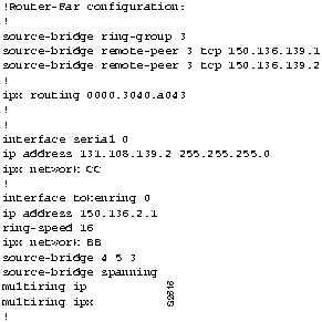
Figure 8-5 and Figure 8-6 provide relevant configuration listings for Router-Corp and Router-Far. These configurations illustrate changes required to ensure proper RIF updating and a contiguous network addressing scheme.
Figure 8-5 : Relevant Router-Corp Final Configuration
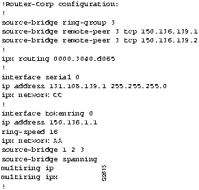
Figure 8-6 : Relevant Router-Far Final Configuration
Translational Bridging, SRT Bridging, STUN, SDLC, and SDLLC Connectivity Scenario
Cisco provides IBM connectivity options that range from support for source-route bridging (SRB) and source-route transparent (SRT) bridging to translational bridging and SDLC Transport over TCP/IP. Thus, network managers can tailor router configurations to the specific needs of existing networks and reconfigure routers to respond to network changes.
The scenario that follows illustrates some common pitfalls encountered in implementing internetworking solutions in complex IBM networks. This scenario focuses on potential problems associated with translational bridging, SRT bridging, serial tunneling (STUN), Synchronous Data Link Control (SDLC) Transport, and SDLC-to-Logical Link Control type 2 translation (SDLLC).
Symptoms
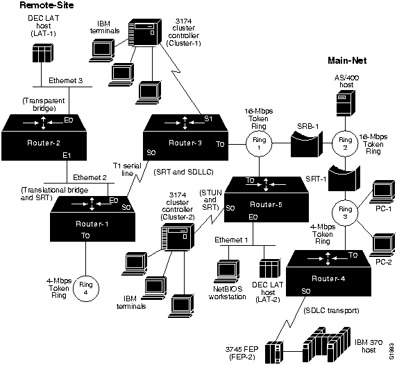
The large-scale corporate network illustrated in Figure 8-7 is composed of multiple Ethernet and Token Ring segments partitioned with SRBs, SRT bridges, a transparent bridge, and a translational bridge.
Connectivity problems on this network are as follows:
- Nonsource-route-capable end system (PC-2) on Ring 3 cannot communicate with either of the DEC Local Area Transport (LAT) Servers LAT-1 and LAT-2 on Ethernet 3 and Ethernet 1, respectively.
- Source-route-capable end system (PC-1) on Ring 3 cannot reach LAT-2 on Ethernet 1.
- IBM 3174 cluster controller (Cluster-2) attached to Router-5 cannot communicate with IBM 3745 front-end processor (FEP-2) attached to Router-4.
- IBM 3174 cluster controller (Cluster-1) cannot communicate with the IBM AS/400 attached to Ring 2.
Environment Description
Figure 8-7 illustrates a map of the environment discussed in this scenario. The following summarizes the relevant elements of this internetworking environment:
- The corporate network (Main-Net) consists of an Ethernet and three Token Rings separated by both Cisco and non-Cisco internetworking devices.
- Remote-Site is interconnected via a T1 serial link between Router-1 and Router-3. Remote-Site includes two Ethernets (Ethernet 2 and Ethernet 3) and a single Token Ring.
- Cisco devices are configured as follows: Router-5 is configured for SRT bridging and STUN; Router-4 is configured for SDLC Transport; Router-3 is configured for SRT bridging and SDLLC; Router-1 is configured for translational bridging and SRT bridging; and Router-2 is configured for transparent bridging only.
- Non-Cisco internetworking devices at Main-Net are as follows: a source-route bridge (SRB-1) connects Ring 1 and Ring 2 and an SRT bridge (SRT-1) connects Ring 2 and Ring 3.
- Token Ring LANs are 4-Mbps and 16-Mbps, IEEE 802.5 compliant; Ethernets are IEEE 802.3 compliant.
- All the serial links from FEPs and cluster controllers to Cisco routers are 56-Kbps SDLC lines.
- The network applications running over the WAN include file transfer, mail, Novell, and both DEC LAT and IBM 3270 terminal connections.
- Other protocols can be routed within this environment, but the focus in this scenario is on mixed-technology bridging issues.
Figure 8-7 : Initial IBM Internetwork Problem Environment
Diagnosing and Isolating Problem Causes
Before attempting to define a specific problem, it is important to identify the most likely causes and to then systematically eliminate each one. Given the situation, the following problems are the best candidates for interconnection failures:
- Incompatibilities between end systems and intermediate systems in mixed-media, multiprotocol environment.
- Packets with RIF being dropped by SRT bridges attached to Ethernets.
- Missing ethernet-transit-oui command.
- Missing multiring commands. Multiring is not needed in Router-[1|2].
- Missing sdllc partner or sdllc xid commands in SDLC-to-LLC translation configuration.
The next step is to eliminate each potential cause as the problem source and then test the network to determine whether it is operational. The following discussion works through the process of problem isolation.
Detecting Incompatibilities between End Systems and Intermediate Systems
In the first symptom, PC-2 is unable to access either of the target DEC LAT servers (LAT-1 and LAT-2). With an SRB in the path to both, PC-2 itself becomes a suspect. In particular, its ability to support SRB is in question. The following steps suggest ways to determine whether the system is source-route capable:
Step 1 Place a network analyzer on Ring 3 (the same ring to which end system PC-2 is connected).
Step 2 Look for any frames sent by the end system (PC-2) with the high-order bit of the source address set to 1. Figure 8-8 illustrates output from the network analyzer, with the high-order bit of the source address set to 1.
Figure 8-8 : Output from a Network Analyzer Showing SRB-Capable End System Source Address
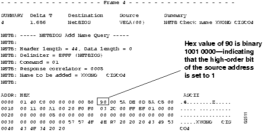
Step 3 If you cannot find a frame with the high-order bit of the source address set to 1, the end system does not support RIF and is not able to participate in source routing.
Step 4 If the end system supports source routing, replace SRB-1 with an SRT bridge to get its traffic through to LAT-1 and LAT-2. This network change is addressed later as part of a comprehensive solution; see Figure 8-10 for a revised map and a description of the network changes involved.
Note Make sure the end system (PC-2) is configured to point to the hardware addresses for servers on Ethernet (LAT-1 or LAT-2).
Detecting SRT Bridging/SRB Incompatibilities
In symptom number 2, PC-1 (which is SRB-capable) on Ring 3 can talk to DEC LAT server LAT-1, but cannot talk to DEC LAT server LAT-2. As with the preceding problem, the key here rests with technology differences between the internetworking devices in the path to the servers and the end system trying to make a connection.
The likely stopping point for traffic in this case is Router-5, which is configured as an SRT bridge. Because Router-5 is attached to both a Token Ring and an Ethernet segment (and is configured for SRT bridging), it discards packets that include RIF data. Determine whether the end system (PC-1) is source-route capable. The steps to remedy this problem are analogous to the prior procedure, with some slight differences:
Step 1 Place a network analyzer on Ring 3 (the same ring to which end system PC-1 is connected).
Step 2 Look for frames sent by the end system (PC-1) with the RIF present. Figure 8-9 illustrates output from the network analyzer with RIF present.
Figure 8-9 : Output from the Network Analyzer Showing an End System Packet with RIF
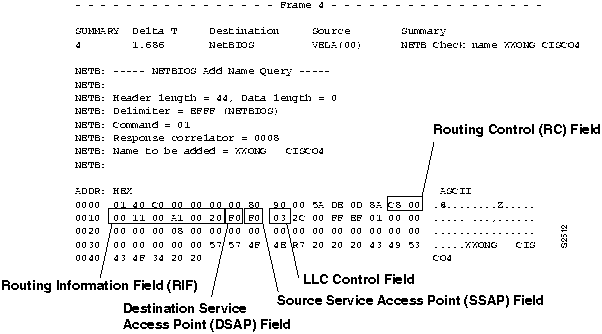
Step 3 If you find a frame with the high-order bit of the source address set to 1 (see Figure 8-8), PC-1 is source-route capable. The RIF illustrated in Figure 8-9 specifies that the frame came from Ring 001 (hexadecimal) over bridge 1 (hexadecimal), through Ring 00A (hexadecimal) over bridge 1 (hexadecimal) to Ring 002 (hexadecimal). Note that Bridge 0 is valid though not often seen.
Step 4 In this case, an end system with a RIF is a problem. When Router-5 sees the RIF in packets sent from PC-1, it will drop those packets rather than put them on the Ethernet interface.
Step 5 To get traffic from PC-1 through to LAT-2, you can enable translational bridging on Router-5 or replace SRB-1 with an SRT bridge. This network change is part of a comprehensive solution described in the section "Problem Solution Summary," later in this chapter.
Note Make sure the end system (PC-1) is configured to point to the hardware addresses for servers on Ethernet (LAT-1 or LAT-2) in order to be able to listen to their service advertisements.
Resolving Vendor Code Mismatch Problems
Older Token Ring implementations, such as the IBM 8209, expect the vendor code (OUI) field of the SNAP header to be 000000. Cisco routers modify this field to be 0000F8 to specify that the frame was translated from Ethernet Version 2 to Token Ring. Cisco's modification of this field can cause end systems that expect the SNAP header to be 000000 to drop packets. The ethernet-transit-oui interface configuration command forces the router to make the vendor code field 000000.
To determine whether you need to add the ethernet-transit-oui interface configuration command to the configuration of a router, follow these steps:
Step 1 On the router acting as a translational bridge (Router-1), use the write terminal EXEC command and look for the ethernet-transit-oui interface configuration command.
Step 2 If the ethernet-transit-oui interface configuration command is not present and if frames are getting through the translational bridge, but some workstations are dropping packets, specify the ethernet-transit-oui interface configuration command on Router-1. This command forces the router to make the vendor code field 000000.
- For more information, refer to the Router Products Configuration Guide and Router Products Command Reference publications.
Finding Missing multiring Commands
If routed protocols are not making it through an environment consisting of SRBs, look for missing multiring Token Ring interface configuration commands.
Symptom number 3 is a 3174 cluster controller (Cluster-2) that cannot communicate with FEP-2. In this scenario, SDLC Transport (tunneling) is implemented via IP encapsulation. This configuration suggests that Router-4 or Router-5 is missing the multiring interface configuration command, which is required as a result of routing between Router-4 and Router-5.
The following steps outline actions for determining whether you should add the multiring interface configuration command to the configuration of a router:
Step 1 Use the ping EXEC command to determine whether Router-5 can communicate with Router-4.
Step 2 Use the write terminal EXEC command (on Router-4 and Router-5) to look for a multiring interface configuration command that includes the ip keyword option, or the all keyword option, for the Token Ring interfaces.
Step 3 Assuming that the multiring command is not included or does not cover a particular protocol that is being routed (and subsequently bridged over the SRB as in this scenario), you can add the multiring ip command to Router-4 (Token Ring interface T0) and Router-5 (Token Ring interface T0), as illustrated in Figure 8-7.
Step 4 Another option is to reconfigure to eliminate this problem. See Figure 8-10 for a revised map and a description of the network changes involved. Removing SRB-1 and SRT-1 remedies the problem without requiring the addition of the multiring ip command.
Enabling Access to the AS/400 on Ring 2
The last symptom in the scenario is the 3174 cluster controller (Cluster-1) that cannot communicate with the AS/400 host that is directly attached to Ring 2. The following procedure isolates and suggests ways to resolve this problem:
Step 1 Place a network analyzer on Ring 1 (the same ring to which Router-3 is connected), or use the debug sdllc EXEC command on Router-3.
Step 2 Determine whether Router-3 is generating explorer packets for the AS/400.
Step 3 If Router-3 is not generating explorer packets for the AS/400, check its configuration for inclusion of the sdllc partner interface command and sdllc xid interface configuration command.
Step 4 If not present, add the sdllc partner and sdllc xid commands. These commands force the router to generate explorer packets.
Problem Solution Summary
Several of the solutions in this scenario pointed to a redesign of the original network as illustrated in Figure 8-7. Figure 8-10 presents a suggested reconfiguration of the internetwork. The modification includes the replacement of SRB-1 and SRT-1 by an AGS+ Cisco router and the implementation of SRT bridging on all Main-Net Token Ring links.
This scenario addressed a number of common problems encountered in complex IBM internetworks. The solutions included the following:
- Resolving SRB-related and SRB/SRT bridging technology conflicts by replacing SRT-1 and SRB-1 with an AGS+ router (Router-4).
- Using third-party diagnostic tools to isolate problems based on traffic occurring on a network.
- Adding a missing ethernet-transit-oui command to applicable configurations to resolve vendor code mismatch problems (Router-1, global configuration change).
- Adding missing sdllc partner commands in SDLLC configurations (Router-3, interface Serial1).
Figure 8-10 : Reconfigured IBM Internetwork Environment
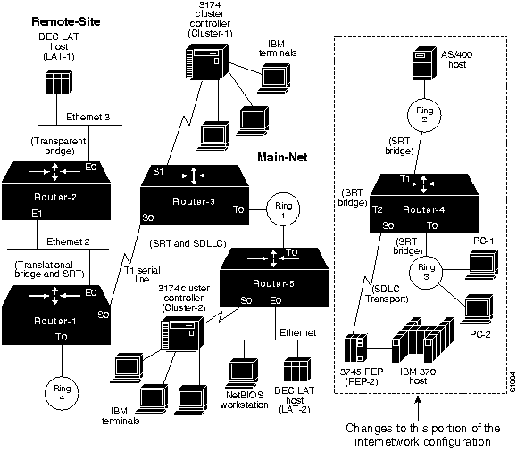
Figure 8-11 through Figure 8-14 provide the complete, final configuration listings for the key routers discussed in this scenario.
Figure 8-11 : Relevant IBM Router-1 Final Configuration Listing
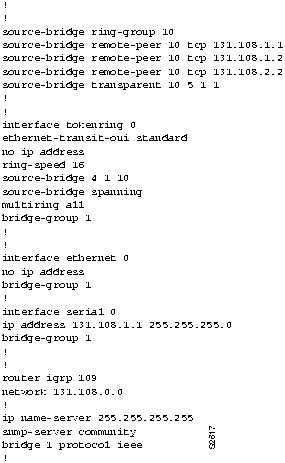
Figure 8-12 : Relevant IBM Router-3 Final Configuration Listing
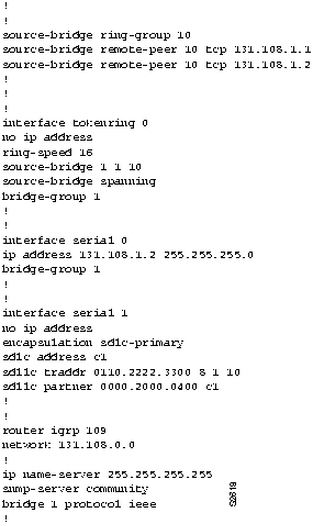
Figure 8-13 : Relevant IBM Router-4 Final Configuration Listing
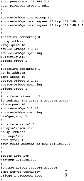
Figure 8-14 : Relevant IBM Router-5 Final Configuration Listing
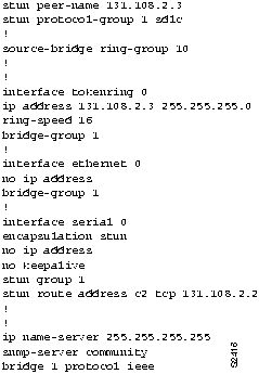
IBM Network and Token Ring Connectivity Symptoms
The symptom modules that follow pertain to IBM internetworking problems. There are modules for the following topics:
Router Is Unable to Connect to Token Ring
Symptom: When installing a new router in a Token Ring environment, you find that the router will not connect to the ring. Table 8-1 outlines possible causes and suggested actions when a router fails to connect to a Token Ring.
Table 8-1 : IBM: Router Is Unable to Connect to Token Ring
Relay open in MAU
|
Step 1 If, at system power-on, an "open lobe fault" message appears on the console (or VTY) connected to the router, check the cable connection to the Multistation Access Unit (MAU).
Step 2 Use the clear interface privileged EXEC command to reset the Token Ring interface and reinsert the router into the ring.
- For all Token Ring cards except the CTR and low-end routers, you must use the clear interface command to reinitialize the Token Ring interface if the interface is down.
Step 3 Use the show interfaces token EXEC command to verify that the interface and line protocol are up.
Step 4 If the interface is operational, but the "open lobe fault" message persists, and the router continues to be unable to connect to its ring, connect the router to a different MAU port.
Step 5 If the "open lobe fault" message continues to appear, disconnect all devices from the MAU and reset the MAUs relay with the tool provided by the MAU vendor.
Step 6 Reattach the router and determine whether it can connect to the ring. If resetting the relay does not remedy the problem, try replacing the MAU with one that is known to be operational.
Step 7 If the router is still unable to connect to the ring, check internal cable connections of the router Token Ring cards. Ensure that cables associated with the respective port numbers and applique numbers are correctly wired and that they are not swapped.
Step 8 If the router still cannot connect to the ring, replace the cables that connect the router to the MAU with working cables.
Step 9 Use the clear interface command to reset the interface and reinsert the router into the ring. Use the show interfaces token command to verify that the interface and line protocol are up.
Step 10 Alternatively, you can connect the router to a spare MAU to which no stations are connected. If the router is able to attach to the ring, the original MAU should be replaced. |
| Duplicate Media Access Control (MAC) address |
Step 1 Use a network analyzer to check all MAC addresses of stations on the ring.
Step 2 Change a MAC address by reinitializing one of the nodes that has a duplicate address.
- (This problem arises when routers attempt to generate a MAC address.)
|
| LAN Network Manager (LNM) is blocking insertion |
Step 1 Disable LNM on the ring.
Step 2 Retry inserting the router into ring.
Step 3 If you are able to insert the router into the ring after disabling LNM, reconfigure your LNM table to include the address of the router as needed. |
| Congested ring |
Step 1 Insert the router during an off-peak period.
Step 2 If insertion is successful during off-peak periods, but unsuccessful during peak load, segment your internetwork to distribute traffic. |
| Ring Parameter Server (RPS) conflict |
Step 1 Use the no lnm rps interface configuration command to disable the RPS function on the router that you are attempting to insert into the ring.
Step 2 Retry inserting the router into the ring.
Step 3 If you can insert the router with RPS disabled, a conflict exists between RPS implementations. Contact your router technical support representative for more information. |
| Bad ring speed specification |
Step 1 Use the show interfaces token EXEC command to determine the status of the interface.
Step 2 If status line indicates that the interface and line protocol are not up, check the cable from router to the MAU. Make sure that the cable is good; replace if necessary.
Step 3 If the show interfaces token EXEC command indicates that the interface and line protocol are up, use the ping command between routers to test connectivity.
Step 4 If the remote router does not respond, check the ring speed specification on all of the nodes that are attached to the Token Ring backbone. The ring speed for all of the nodes must be the same. (Ring speed conflicts cause the ring to beacon.)
Step 5 Modify ring speed specifications for clients, servers, and routers as necessary. For routers that support setting the ring speed in software, use the ring-speed interface configuration command. Change jumpers as needed for modular router platforms. For more information about ring speed specification, refer to the hardware installation and maintenance manual for your system. |
Routing Does Not Function in SRB Environment
Symptom: SRBs are bridging traffic as they should, but routed protocols are not getting through a router. If this symptom occurs, you must route certain protocols (for example, Novell IPX) through an internetwork that is dominated by SRB links. Table 8-2 outlines a possible cause and suggested actions when routing does not function in an SRB environment.
Table 8-2 : IBM: Routing Does Not Function in SRB Environment
| Misconfigured router; routing a protocol and attempting to communicate with host on another ring across an SRB bridge |
Step 1 Check the configuration for inclusion or absence of a multiring protocol-name interface configuration command.
Step 2 Add a multiring protocol-name interface configuration command to the router configuration if it is missing.
Step 3 For IP networks, make sure that the end system is pointing to the Token Ring address of the router as the default gateway. If a UNIX host is running routed, check its default routes.
Step 4 Determine whether a host can respond using the ping command. If it does not respond, use the show arp EXEC command to determine whether an entry for the host exists in the ARP table. If an entry exists, use the show rif EXEC command to match the RIF with the hardware address of the host.
Step 5 Try the steps outlined in the next symptom module, "Routing in SRB Network Fails Unexpectedly."
Step 6 Contact your router technical support representative if you still cannot get traffic intended to be routed to transit the router. |
Note For illustrations and additional context-related information, refer to the section "Concurrent Routing and SRB Connectivity Scenario" earlier in this chapter.
Routing in SRB Network Fails Unexpectedly
Symptom: Routing is working in an environment dominated by SRB links, then halts without any known administrative changes in the network. Table 8-3 outlines a possible cause and suggested actions when routing in an SRB network fails unexpectedly.
Table 8-3 : IBM: Routing in SRB Network Fails Unexpectedly
| Software bug in the end system software |
Step 1 Use the show interfaces EXEC command to determine whether the protocol is up. If the protocol is up, and the 5-minute input/output rate has not dropped to zero, and there are no input or output errors, check the ring status.
Step 2 If the last ring status line shows a soft error, use the show controllers token EXEC command to determine whether there have been any line or burst errors on the ring. If no errors appear, skip the next step.
Step 3 Place a network analyzer on the ring to determine which node is injecting errors into the ring. Contact your router technical support representative for additional assistance.
Step 4 Use the show rif EXEC command to determine whether the MAC address for an end system is missing from the RIF table.
Step 5 If a MAC address for an end system is missing, issue the clear rif-cache and clear arp-cache privileged EXEC commands. Then ping the end system to determine whether it can respond.
Step 6 If the end system does not respond, use a network analyzer to look for XID-to-NULL SAP packets (LSAP value of 00) sent by the router to the end system. The XID-to-NULL SAP packets are generated when the router's RIF entry for a workstation ages out, and the RIF table is being updated.
- If you see the XID packet and the end system does not reply, there is probably a bug in the end system software.
Step 7 Upgrade your host software or contact your end system technical support representative for more assistance.
Step 8 If you do not see the XID packet, or if the station replies but you still cannot establish communication, contact your router technical support representative.
Step 9 If the MAC address of the end system is present in the RIF table, use the show arp EXEC command to examine the ARP cache. If the IP address of the end system is not in the ARP cache, there probably is a problem with IP rather than with the SRB path to the router.
Step 10 As a last resort, enable the debug token ring privileged EXEC command. This command can provide useful information, but generates traffic that can break poorly performing networks. Use this command with great care. |
No Communication over SRB
Symptom: A router configured to operate as an SRB that connects two or more Token Rings is not forwarding SRB traffic. Table 8-4 outlines possible causes and suggested actions when no communication is occurring over an SRB.
Table 8-4 : IBM: No Communication over SRB
| Misconfigured router; ring number mismatch |
Step 1 Get the ring number (specified in hexadecimal) from IBM SRBs.
Step 2 Use the write terminal privileged EXEC command to look for the source-bridge local-ring bridge-number remote-ring interface configuration command that assigns ring numbers (displayed in decimal) to the rings that are connected to the router's interfaces.
- (Although you can enter the ring number in hexadecimal or decimal, it always appears in the configuration as a decimal number. Also note that parallel bridges situated between the same two rings must have different bridge numbers.)
Step 3 Convert IBM SRB ring numbers to decimal and verify that the ring numbers for all internetworking nodes agree.
Step 4 If the ring numbers do not agree, reconfigure the router's interface so that its ring number matches the IBM SRB.
Step 5 If you still cannot communicate over the SRB, contact your technical support representative. |
| End system does not support RIF |
Step 1 Place a network analyzer on the same ring to which the end system is connected.
Step 2 Look for any frames sent from the end system with the first bit of the source MAC address set to 1. Refer to the section entitled "Translational Bridging, SRT Bridging, STUN, SDLC, and SDLLC Connectivity Scenario" earlier in this chapter for illustrations and additional context-related information.
Step 3 If no such frames are found, the end system does not support RIF and is not able to participate in source routing.
Step 4 If the protocol is routable, you can configure the router to act as an SRT bridge and route the protocol.
Step 5 If your environment requires SRB, contact your workstation or server vendor for SRB drivers or for information about setting up SRB on your workstation or server. |
End system configured to send spanning explorers, but router not configured to forward them
(A spanning explorer is equivalent to a single-route broadcast.) |
Step 1 Place a network analyzer on the same ring to which the end system is connected.
Step 2 Look for any frames sent from the end system with the first bit of the source address set to 1.
Step 3 If such frames are found, determine whether the frames are spanning all-ring frames (that is, the first two bits are set to 1).
Step 4 If you find spanning all-ring frames, determine whether the router is configured to forward spanning explorers (using the source-bridge spanning interface configuration command).
Step 5 If necessary, add the source-bridge spanning interface configuration command to any router that is required to pass spanning explorers.
Step 6 Use the show source-bridge EXEC command to determine whether the explorer count is incrementing.
Step 7 If sessions still cannot be successfully established over the SRB, contact your technical support representative for more assistance. |
Blocked Communication over Remote SRB
Symptom: Users are unable to communicate over a remote SRB. As a remote SRB, a router uses encapsulated Token Ring packets to allow interconnection of Token Ring networks over any non-Token Ring media type (such as a Fiber Distributed Data Interface [FDDI] backbone, point-to-point serial lines, or a packet-switched network). Table 8-5 outlines possible causes and suggested actions when communication over a remote SRB is blocked.
Table 8-5 : IBM: Blocked Communication over Remote SRB
| Misconfigured source-bridge remote-peer global configuration commands on the router |
Step 1 Use the write terminal privileged EXEC command to verify that the source-bridge remote-peer command is pointing to the correct IP address on each router.
Step 2 Modify configuration as required.
Step 3 Use the show source-bridge EXEC command to check for the existence of remote peers. |
| End system does not support RIF |
Step 1 See Table 8-4 for suggested actions. |
| Hop count exceeded |
Step 1 Use the show protocol route command to check the hop count values on the routers and other bridges in the path.
Step 2 Alternatively, you can enable the debug source event privileged EXEC command to see whether packets are being dropped because the hop count has been exceeded. |
| No route to the remote peer (TCP/IP encapsulation) |
Step 1 Check the result of the show ip route EXEC command. If a route to the intended remote peer is not included in the list, create a route or check the state of devices and cabling in the path to the remote peer.
Step 2 Verify IP connectivity; try to ping from the router to the remote peer IP address. If the remote peer does not reply, the SRB frames cannot get through. If it does reply, IP routing is operational. |
| Serial link problem |
Step 1 Use the show interfaces EXEC command to verify that the interface and line protocol are up. Refer to Chapter 3, "Troubleshooting Serial Line Problems," if the status line indicates any other condition.
Step 2 Verify that the selected encapsulation type matches the requirements of the network to which the serial interface is attached. |
| Peer problems |
Step 1 Use the show source-bridge EXEC command to determine whether the peer is "open" between routers. If the peer is not open, routers cannot communicate.
Step 2 Use the show source-bridge command to determine whether the remote router can see the ring.
- If devices are not present on both rings, peers may not open, or peers may not appear in the show source-bridge display.
Step 3 If devices are present on both rings and peers are open, but communication is still blocked over the remote SRB connection, contact your router technical support representative for more assistance. |
Intermittent Communication Failures over Remote SRB
Symptom: Sessions time out over a router configured for remote SRB. Table 8-6 outlines a possible cause and suggested actions when intermittent communication failures occur over a router configured as a remote SRB (encapsulated SRB over any non-Token Ring media).
Table 8-6 : IBM: Intermittent Communication Failures over Remote SRB
| Sessions are timing out |
Step 1 Place a network analyzer on the ring local to the source station and look for acknowledgments that appear on the local ring after the transmission timeout period.
Step 2 Perform a ping test to the remote router and note the round trip delay. Compare this value with the timeout value. If the round trip delay is close to or exceeds the timeout value, increase the timeout parameter. If the measured delay is close to or exceeds the timeout value, modify the timeout configuration at the source station.
Step 3 Use the show interfaces EXEC command to check for dropped packets on all interfaces in the path.
Step 4 If you are using TCP encapsulation, use the show tcp EXEC command to check the retransmission count for the peer in question.
Step 5 Use a network analyzer to capture traffic for six or seven stations that have connectivity problems.
Step 6 Adjust protocol parameters as described in the Router Products Configuration Guide and Router Products Command Reference publications. In particular, the various LLC2 timer values may need tuning.
Step 7 On low-end routers, verify that the allocated buffers are adequate. Use the show buffers command, and look for misses in small, middle, or big buffers. Tune the number of buffers if there are many misses. For details, see the section "Adjusting Buffers to Ease Overutilized Serial Links" in the "Troubleshooting Serial Line Problems" chapter. |
NetBIOS Clients Cannot Connect to Servers over Remote SRB
Symptom: Users on NetBIOS clients complain that they cannot establish connections to NetBIOS servers over routers acting as remote SRBs. Table 8-7 outlines possible causes and suggested actions when NetBIOS clients cannot connect to NetBIOS servers over a remote SRB.
Table 8-7 : IBM: NetBIOS Clients Cannot Connect to Servers over Remote SRB
| Incorrect mapping of NetBIOS name cache server-to-client mapping |
Step 1 For each router on which NetBIOS name caching is enabled, use the show rif EXEC command to determine whether the RIF entry shows the correct path from the router to both the client and the server.
Step 2 Use the write terminal privileged EXEC command to ensure that the source-bridge proxy-explorer interface configuration command is included in the Token Ring configuration. Proxy explorers must be enabled on any interface that uses NetBIOS name caching.
Step 3 Use the show netbios EXEC command to see if the NetBIOS cache entry shows the correct mapping from server name and client name to MAC address.
Step 4 Use the write terminal privileged EXEC command at each router to examine the mapping of addresses specified in the netbios name-cache global configuration command. Change any mappings that are not correct. |
| Incorrect specification of remote peer parameters in source-bridge specification |
Step 1 For each router on which NetBIOS name caching is enabled, use the show source-bridge command to obtain the version of the remote connection. The value specified should be 2 or 3. If the value is 1, connections will not get through, and you must modify your configuration.
Step 2 If the router is running a software release prior to Cisco Internetwork Operating System (Cisco IOS) Release 10.0, specify either version 2 or version 3 in the source-bridge remote-peer interface configuration command. If the router is running Cisco IOS Release 10.0 or later, the specification of a version is ignored. |
Note Whenever NetBIOS name caching appears not to be running between a particular client and server, capture traces of packets that apparently are not flowing. In addition, get the output of the show rif, show netbios, and show source EXEC commands for the routers at each end of the remote SRB cloud. The output of these commands can help diagnose a NetBIOS name caching problem by providing information about the state of the router.
Users Cannot Communicate over Cisco Translational Bridge
Symptom: Routers allow for the translation of transparent bridging and source-route bridging between Ethernet and Token Ring, respectively. Under certain circumstances, this translation may not work, which results in an apparent failure of translational bridging.
 Caution In certain situations, replacing existing translational bridges with Cisco translational bridges can cause interoperability problems. Some translational bridge implementations map functional addresses between media (such as LAT functional address 0900.2B00.00FA on Ethernet) to a broadcast address on the Token Ring ring side (such as C000.FFFF.FFFF). Cisco does not support this functionality. Furthermore, you cannot use translational bridging with any protocol that embeds the MAC address of a station inside the information field of the MAC frames (examples include IP ARP and Novell IPX).
Table 8-8 outlines possible causes and suggested actions when users cannot communicate over Cisco routers configured for translational bridging.
Table 8-8 : IBM: Users Cannot Communicate over a Translational Bridge
| Router does not support Ethernet-to-Token Ring address mapping |
Step 1 Use the show bridge EXEC command to verify the existence of the Ethernet station.
- (Ethernet and Token Ring addresses use opposite bit orderings. A Token Ring address of 0110.2222.3333 would be an Ethernet address of 8008.4444.cccc.)
Step 2 Use the show spanning EXEC command to determine whether the Ethernet port is in forwarding mode.
Step 3 Use the show rif EXEC command to determine whether the target Token Ring station is visible on the internetwork.
- (When configured for translational bridging, the router extracts the RIF of a packet received from the Token Ring side and saves it in a table. The router then transmits the packet on the Ethernet side. Later, the router reinserts the RIF when it receives a packet destined for the originating node on the Token Ring side.)
Step 4 If Ethernet and Token Ring end systems are visible, statically configure any relevant server MAC addresses in the client configurations, so the clients can listen to the server advertisements directly.
- (One case in which static mapping is required is when bridging DEC LAT traffic over a translational bridge. LAT services on Ethernet are advertised on a multicast address that is mapped by some translational bridges to a broadcast address on the Token Ring side. Routers do not support this mapping.)
|
| Vendor code mismatch |
Step 1 Specify the ethernet-transit-oui interface configuration command to force the router to make the vendor code field 000000. This change is frequently required when there are IBM 8209s (IBM Token Ring-to-Ethernet translating bridges) in the same network.
- (Older Token Ring implementations expect the vendor code [OUI field] of the SNAP header to be 000000. Cisco routers modify this field to be 0000F8 to specify that the frame was translated from Ethernet Version 2 to Token Ring.)
|
| Adding Cisco translational bridging destabilizes network, blocks all traffic |
Step 1 Check for preexisting translational bridges in parallel with the Cisco translational bridge; any that are left in place will result in loops.
Step 2 Because implementing translational bridging defeats the spanning tree mechanism of both transparent bridging and SRB environments, you must eliminate all loops caused by inserting the translational bridge. |
| Trying to bridge protocols that embed MAC addresses in the Information field of the MAC frame (such as IP ARP and IPX) |
Step 1 Route these protocols.
Step 2 If you still cannot communicate over the router, contact your technical support representative. |
Traffic Cannot Get through Router Implementing SRT Bridging
Symptom: Packets cannot traverse a router configured to support SRT bridging. Table 8-9 outlines possible causes and suggested actions when traffic cannot get through a router configured for SRT bridging.
Note SRT bridging allows you to implement transparent bridging in Token Ring environments. It is not a means of translating between SRB on a Token Ring and transparent bridging on Ethernet (or other) media. This confusion is sometimes the cause of blocked traffic in multimedia environments.
Table 8-9 : IBM: Traffic Cannot Get through a Router Implementing SRT Bridging
| Trying to bridge frames containing RIF from the Token Ring side to the Ethernet side over an SRT bridge |
Step 1 Use translational bridging instead of SRT bridging to allow SRB-to-transparent bridging translation.
- Because SRT bridging only works between Ethernet and Token Ring, any packet containing a RIF is dropped when SRT bridging is used.
|
| Hardware does not support SRT bridging |
Step 1 For each router interface configured to support SRT bridging, examine the output of the show interfaces token number EXEC command to determine whether the Token Ring interface is capable of SRT bridging.
Step 2 Check all other bridges in the network for SRT bridging support.
Step 3 Make sure that the software and microcode are compatible with SRT bridging for all internetworking devices; upgrade as needed. |
| Attempting to transfer large frame sizes (exceeding Ethernet MTU of 1500 bytes) |
Step 1 Configure hosts to generate frame sizes less than or equal to Ethernet MTU (1500 bytes). |
| Trying to bridge protocols that embed the MAC address in the Information field of the MAC frame (such as IP ARP and IPX) |
Step 1 Route these protocols.
Step 2 If you still cannot communicate over the router, contact your technical support representative. |
Intermittent Connectivity over Router Configured for SDLC
Symptom: User connections to hosts time out over a router configured to support SDLC Transport. Table 8-10 outlines a possible cause and suggested actions when connectivity to hosts is intermittent over a router configured for SDLC.
Table 8-10 : IBM: Intermittent Connectivity over Router Configured for SDLC
| SDLC timing problems |
Step 1 Place a serial analyzer on the serial line attached to the source station and monitor packets.
Step 2 If duplicates appear, check the configuration for the local-ack keyword at the end of the stun route address interface configuration command.
Step 3 If the local-ack keyword is missing, add it to both router configurations for SDLC interfaces.
Step 4 Adjust the SDLC protocol parameters described in the Router Products Configuration Guide and Router Products Command Reference publications. These parameters are used to customize SDLC Transport over various network configurations. In particular, you may need to tune various LLC2 timer values. |
Router Is Not Communicating with IBM SDLC Devices over EIA/TIA-232
Symptom: When installing a router, you find that the router is not able to communicate with an IBM SDLC device over an EIA/TIA-232 (formerly RS-232) cable.
Note When debugging serial line physical layer problems, it is important to observe indicator lights on appliques, LEDs on modems and modem eliminators, and line drivers. The indicator lights help you to determine whether the hardware is having any problems and can save debugging time.
Table 8-11 outlines a possible cause and suggested actions when a router is apparently not communicating with IBM SDLC devices over EIA/TIA-232.
Table 8-11 : IBM: Router Is Not Communicating with IBM SDLC Devices over EIA/TIA-232
| Physical layer mismatch |
Step 1 Make sure that both the IBM device and the router implement the correct signal coding (NRZ or NRZI).
Step 2 If the IBM device supports full-duplex NRZ, make sure that it is set for full-duplex NRZ (set Request to Send [RTS] high). For full-duplex configurations, set the signal high by strapping Data Terminal Ready (DTR) from the IBM side to RTS on the router side.
Step 3 For AS/400 multidrop devices, make sure that Carrier Detect (CD) is tied to ground in the serial line that connects the router to the primary link station.
Step 4 Use the show interfaces EXEC command to determine whether the interface and line protocol are up.
Step 5 If the router is set up as a data terminal equipment (DTE) device, make sure that the clocking source configurations match for all devices. Also make sure that the modems and modem eliminators are properly configured.
Step 6 When installing routers in IBM environments, make sure that the IBM devices are properly configured to communicate with each other. For example, make sure that cluster controllers can talk to FEPs before adding a router.
Step 7 Make sure that the clock rate matches the network's externally derived clock.
Step 8 Regardless of whether the router is configured as DTE or data communications equipment (DCE), try reducing the line speed to 9600 baud.
Step 9 Because the EIA/TIA-232 clocking signal is weak, cable length must not exceed 50 feet (15.24 meters); 25 feet (7.62 meters) is the recommended length. |
SDLC Sessions Fail over Router Running STUN
Symptom: SDLC sessions between two nodes are not coming up when they are attempted over a router that is running STUN. An underlying symptom is that the handshaking required to complete SDLC sessions is not occurring. Table 8-12 outlines possible causes and suggested actions when SDLC sessions fail over a router running STUN.
Table 8-12 : IBM: SDLC Sessions Fail over Router Running STUN
| Broken physical connectivity of SDLC secondary stations and the STUN peer |
Step 1 Use the show stun EXEC command to check the STUN state.
Step 2 If the output of the show stun EXEC command indicates that the STUN is "closed," check physical connectivity as described in the "Router Is Not Communicating with IBM SDLC Devices over EIA/TIA-232" symptom module earlier in this chapter. |
| Misconfigured stun route address interface configuration command |
Step 1 Use the show stun EXEC command to check the STUN state.
Step 2 If the output of the show stun EXEC command indicates that the STUN is "open," use the debug stun-packet privileged EXEC command to look for Set Normal Response Mode (SNRM) and matching unnumbered acknowledgment (UA) packets. Ensure that the SNRMs and UAs that have SDLC addresses corresponding to the relevant secondary stations are getting to the correct router.
Step 3 If SNRMs are indicated in the debug stun-packet command output, but UAs are not indicated as returning, use the write terminal privileged EXEC command on the router to which the primary link station is attached.
Step 4 Look for the SDLC address specified in the stun route address interface configuration command. Entries for this command should point to relevant secondary link stations. (Routers do not support the stun route all functionality for SDLC; routers only support the basic STUN transport protocol.) |
| Misconfigured stun peer-name global configuration command |
Step 1 At the router to which the secondary link station is attached, enable the debug stun-packet privileged EXEC command and look for SNRMs for that peer.
Step 2 If no SNRMs appear in the output, check the stun peer-name commands on the router to which the primary link station is attached. Make sure that this command specifies the IP address of the router correctly. |
| Physical connectivity problem from the secondary link station to the router; misconfigured stun route address interface configuration command on router to which the secondary link station is attached; or, broken IBM equipment |
Step 1 At the router to which the secondary link station is attached, enable the debug stun-packet privileged EXEC command and look for SNRMs for that peer.
Step 2 If you do see SNRMs, use the show interfaces serial EXEC command to see if output drops are accumulating. Accumulating output drops suggest that the router is not communicating with the secondary link station.
Step 3 For 3174s, if output drops are not accumulating, check the front panel display for values cycling between 505 and 532. This cycling of values indicates that SNRMs are getting to the 3174, but the receiver ready signal is not initializing.
Step 4 Check the output of the debug stun-packet privileged EXEC command to see if relevant UAs are being detected. If so, physical connectivity and broken IBM equipment can be eliminated as possible causes.
- If the debug stun-packet privileged EXEC command output at the router to which the primary link station is attached displays relevant UAs, the problem is isolated to a physical connectivity problem from that router to the primary link station.
Step 5 Check physical connectivity as described in the "Router Is Not Communicating with IBM SDLC Devices over EIA/TIA-232" symptom module earlier in this chapter. |
Users Cannot Make Connections over Router Configured for SDLLC
Symptom: Users cannot make session connections to hosts on the other side of a router configured to support SDLLC.Table 8-13 outlines possible causes and suggested actions when users are unable to make host connections over a router configured for SDLLC.
Table 8-13 : IBM: Users Cannot Make Connections over Router Configured for SDLLC
| Missing sdllc partner command |
Step 1 Configure the sdllc partner interface configuration command so that it points the router to the hardware address of the FEP on Token Ring. This command forces the transmission of explorer packets. |
| Missing sdllc xid command |
Step 1 Include the sdllc xid interface configuration command. This command defines XID information (IDBLK and IDNUM) that must match host definitions when any 37X5 or 317X device is being used as a gateway.
Step 2 Check with the system administrators of the hosts to ensure that the XID information is properly defined. If the 317X device is a channel-attached gateway, XID must be 0000000 for IDBLK and IDNUM. |
| Microcode incompatibility |
Step 1 Use the show controller mci EXEC command to obtain the SCI microcode version of the serial card.
Step 2 Upgrade to the latest microcode version. |
| Incorrect RTS signal in full-duplex implementation |
Step 1 Insert a breakout box between the router and the IBM device and monitor the LEDs for correct signaling. EIA/TIA-232 signaling requirements are briefly described in the discussion following this table, "IBM EIA/TIA-232 Signaling Requirements Summary."
Step 2 Check RTS for a continuously active signal from the router.
Step 3 If the signal is not continuously active, set the signal high by strapping DTR from the IBM side to RTS on the router side. Open the RTS connection between the router and the IBM device. For more information concerning physical layer mismatches, see the "Router Is Not Communicating with IBM SDLC Devices over EIA/TIA-232" symptom module earlier in this chapter.
Step 4 Configure the 3174 for permanent RTS by replying with a "1" to question number 340. |
| Incorrect V.35 applique jumper setting |
Step 1 When using the V.35 dual-mode applique as a DCE, remove the SCT/SCTE jumper, which selects SCT and specifies that the timing signal come from the server. |
IBM EIA/TIA-232 Signaling Requirements Summary
When connecting a router to an IBM device with a serial connection, you must verify that the signaling configurations are compatible. Figure 8-15 illustrates a typical serial connection between a router (Router-1) and an IBM device. Assume that the connection is full duplex. A breakout box is inserted to examine signal states on the cable.
Figure 8-15 : Checking IBM Serial Link to Router with Breakout Box
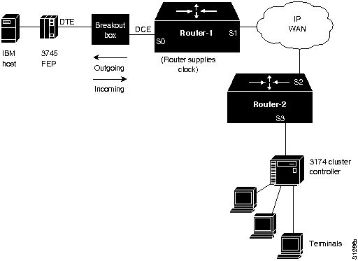
Table 8-14 outlines the key signaling requirements for the full-duplex link between Router-1 and the 3745 FEP. Figure 8-15 illustrates the direction of signals with respect to the router as listed in
Table 8-14. This environment assumes that the router is configured for DCE, while the IBM FEP is configured for DTE.
Table 8-14 : Key Full-Duplex EIA/TIA-232 Signaling Requirements for Router-to-IBM FEP Connection
| 4/RTS |
High |
Incoming |
| 5/CTS |
High |
Outgoing |
| 6/DSR |
High |
Outgoing |
| 8/CD |
High |
Outgoing |
| 20/DTR |
High |
Incoming |
Preventive Actions in SDLLC Environments
When configuring a router for SDLLC operation in IBM internetworking environments, try the following actions for preventing operational problems:
- When configuring SDLLC, the sdllc traddr interface configuration command must point to the virtual ring, not to the physical ring. When using multiple interfaces, the sdllc traddr command specification must be unique for each interface. The virtual ring corresponds to the ring group number specified in the source-bridge ring-group global configuration command. This applies to single router configurations (where the Token Ring and the serial line are both tied to the same router) and multirouter configurations (where the routers are separated by WAN clouds). Also note that the specification of the virtual ring number is the last parameter in the sdllc traddr command.
- SDLLC will not work between an IBM AS/400 and 5394. The AS/400 can only operate as a PU 2 device, while the 5394 can only operate as a PU 1 device. SDLLC only accommodates protocol and frame translation at the DLC level and does not participate in any SNA level exchange. To allow for this kind of translation, you must implement some kind of conversion device for translating PU 1 to PU 2. Routers only support PU 2 devices.
Virtual Token Ring Addresses and SDLLC Implementations
The sdllc traddr command requires the specification of a virtual Token Ring address for an SDLC-attached device (the device that you are spoofing to look like a Token Ring device). The last two hexadecimal digits of the virtual ring address must be 00 because the last byte of the address represents the SDLC address of the station on the serial link.
Assign virtual ring addresses carefully. Any virtual ring address that falls into the range xxxx.xxxx.xx00 to xxxx.xxxx.xxFF belongs to the associated SDLLC serial interface. An IBM locally administered address (LAA) is typically user-defined, and in practice these addresses tend to follow a logical ordering. As a result, there is a real chance that other IBM devices on an internetwork will have an LAA that falls in the same range. If this occurs, problems can arise because routers only examine the first 10 digits of the LAA address of a packet (not the last two, which are considered wildcards). If the router sees a match of the assigned SDLLC LAA address, it automatically forwards that packet to the SDLLC process. In certain cases, this can result in packets being incorrectly forwarded to the SDLLC process and sessions never being established.
Note Before assigning a virtual ring address for any SDLLC implementation, be certain you know the LAA naming convention used in the internetwork to avoid assigning conflicting addresses.
Router Cannot Be Linked from LAN Network Manager
Symptom: A specific router cannot be linked from the LAN Network Manager (LNM) in an SRB environment. Table 8-15 outlines possible causes and suggested actions when a router cannot be linked using LNM.
Table 8-15 : IBM: Router Cannot Be Linked From LNM
| Misconfigured LNM MAC address specifications (universal) |
Step 1 Use the show lnm config EXEC command to determine the Token Ring MAC addresses. They must match the addresses entered on the LNM.
Step 2 If the addresses do not match, enter the Token Ring MAC addresses on the LNM platform. |
| MAC address mismatch when router is connected to a virtual ring (locally administered) |
Step 1 Use the show lnm config command on the router to determine the Token Ring MAC addresses.
Step 2 Make sure that the Token Ring address configured on the LNM matches the address administered on the router. Use the mac-address interface configuration command for each Token Ring interface. This command gives each Token Ring interface a locally administered address (such as 4000.0001.2345). |
Example STUN and SDLLC Diagnostic Sessions
Troubleshooting STUN and SDLLC internetworks can involve a fairly complicated series of diagnostic steps. Even the simplest interconnection requires careful evaluation of each possible problem. This section outlines the basic diagnostic steps for representative STUN and SDLLC internetworking arrangements.
STUN Diagnostic Example
Consider the basic configuration illustrated in Figure 8-16. In this arrangement, an IBM mainframe is channel-attached to an FEP. The FEP is serial-attached to a router (Router-A), which is point-to-point connected over a serial connection to Router-B. Router-B is attached to a cluster controller. Assume that SDLC connections cannot be completed over the routed internetwork illustrated in Figure 8-16.
The following diagnostic tables (Table 8-16 through Table 8-19) outline a process for diagnosing blocked connectivity in this internetwork; the process starts at the FEP and moves to the cluster controller at the other end of the SDLC connection. The diagnostic steps outlined for this example are split into four parts:
- FEP connection diagnostics
- FEP configuration problem diagnostics
- Router STUN problem diagnostics
- Cluster controller problem diagnostics
Figure 8-16 : Typical STUN Interconnection Illustrating Diagnostic Example
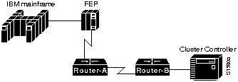
Table 8-16 : FEP Serial Connection Diagnostics (STUN Example)
| Failed serial connection from FEP to router |
Step 1 Use the show interfaces EXEC command at Router-A; look for any indication of a possible problem. For more information about troubleshooting serial connections, refer to the "Troubleshooting Serial Line Problems" chapter. |
| Incorrect IBM cable |
Step 2 Ensure that the correct cable is attached to the FEP. The V.35 cable and the EIA/TIA-232 IBM cable are similar in appearance. The chief difference is that the V.35 cable has three switches while the EIA/TIA-232 cable has only two.
Step 3 Use the show interfaces command to determine whether the interface and line protocol are up, and that the reset counter is not changed. If everything appears normal, proceed to Table 8-17. |
| Incorrect RTS signal in full-duplex implementation |
Step 4 Insert a breakout box between the router and the IBM device and monitor the LEDs for correct signaling.
Step 5 Check RTS for a continuous active signal from the router.
Step 6 If the signal is not continuously active, set the signal high by strapping DTR from the IBM side to RTS on the router side. Open the RTS connection between the router and the IBM device. For more information concerning physical layer mismatches, see the "Router Is Not Communicating with IBM SDLC Devices over EIA/TIA-232" symptom module earlier in this chapter.
Step 7 When using the V.35 dual-mode applique as a DCE, remove the SCT/SCTE jumper, which selects SCT and specifies that the timing signal come from the server. |
| Microcode incompatibility |
Step 8 Use the show controller mci EXEC command to obtain the SCI microcode version of the serial card.
Step 9 Upgrade to the latest microcode version. |
Table 8-17 : FEP Configuration Problem Diagnostics (STUN Example)
| Misconfigured FEP |
Step 1 Check RTS and Clear to Send (CTS) signals; RTS should be active.
Step 2 Check CD and ground; make sure that CD is strapped to ground.
Step 3 Enable the debug stun-packet privileged EXEC command on Router-A.
Step 4 Deactivate and then activate the SDLC lines at the host. Use the following VTAM commands:
- VARY NET,INACT,LINE=xxVARY NET,ACT,LINE=xx
- (where xx is the number of the line being toggled)
Step 5 If SNRMs do not appear in the debug stun-packet output, check the line from the FEP to the serial interface on the router; the NCPGEN on the FEP, and the line number used with the VARY VTAM command as specified at the FEP.
Step 6 If SNRMs appear in the debug stun-packet output, go to Table 8-18; otherwise, go to Table 8-19. |
Table 8-18 : Router STUN Problem Diagnostics (STUN Example)
| Misconfigured stun peer-name global configuration command and stun route address interface configuration command |
Step 1 Enable the debug stun-packet privileged EXEC command at Router-B.
Step 2 If SNRMs appear in the debug stun-packet output at Router-B, misconfigured stun peer-name and stun route address commands might be blocking connectivity. Proceed to Table 8-19.
- (The show stun EXEC command can also provide a clue. It should indicate that the serial link between the routers is in "open" mode.)
|
| Physical serial connection failed |
Step 3 Use the show interfaces EXEC command at Router-A and Router-B to determine whether they are operational. Make sure that the output indicates that both the interface and the line protocol are up.
Step 4 If either the interface or the line protocol is not up, you may have a hardware problem. Check all your physical connections and refer to Chapter 2, "Troubleshooting Router Startup Problems," for hardware diagnostic information. |
| Mismatched SDLC (PU) address |
Step 5 If this serial connection uses direct HDLC encapsulation, verify that the SDLC address is correctly matched with the appropriate interface number. If not, modify as necessary. |
| IP connection is incorrectly defined |
Step 6 If this serial connection uses TCP/IP encapsulation, verify that the IP addresses of the stun route address interface configuration commands at both ends are matched with the IP addresses of the complementary stun peer-name global configuration commands. |
Table 8-19 : Cluster Controller Problem Diagnostics (STUN Example)
| Failed connection at cluster controller |
Step 1 Use the show interfaces EXEC command at Router-B to look for a possible problem. For more information about troubleshooting serial connections, refer to the "Troubleshooting Serial Line Problems" chapter. |
| Incorrect IBM cable |
Step 2 Ensure that the correct cable is attached to the FEP.
Step 3 Use the show interfaces command to determine the status of the interface. If the output indicates that the interface and line protocol are up, and you still cannot establish connectivity, contact your router technical support representative. |
| Incorrect RTS signal in full-duplex implementation |
Step 4 Insert a breakout box between the router and the IBM device, and monitor the LEDs for correct signaling. |
| Incorrect V.35 applique jumper setting |
Step 5 Check RTS for a continuously active signal from the router.
- If the signal is not continuously active, set the signal high by strapping DTR from the IBM side to RTS on the router side. Open the RTS connection between the router and the IBM device. For more information concerning physical layer mismatches, see the "Router Is Not Communicating with IBM SDLC Devices over EIA/TIA-232" symptom module earlier in this chapter.
Step 6 Configure the 3174 for permanent RTS by replying with a "1" to question number 340.
Step 7 When using the V.35 dual-mode applique as a DCE, remove the SCT/SCTE jumper, which selects SCT and specifies that the timing signal come from the server. |
| Cluster controller configuration problem |
Step 8 Determine whether the cluster controller is operational.
Step 9 If the cluster controller is not up, or if UAs are not returning from the controller, check the configuration of the controller and make sure that it is properly set; look for PU address, NRZI, and NRZ specification errors. |
| Microcode incompatibility |
Step 10 Use the show controller mci EXEC command to obtain the SCI microcode version of the serial card.
Step 11 Upgrade to the latest microcode version. |
SDLLC Diagnostic Example
Figure 8-17 illustrates an example SDLLC environment. An IBM mainframe is channel-attached to an FEP. The FEP and Router-A are both attached to a Token Ring. Router-A is point-to-point connected to Router-B, and Router-B is SDLC-attached to a cluster controller. For SDLLC troubleshooting, start with the SDLLC router---in this case Router-B. Assume that SDLLC connections cannot be completed over the routed internetwork illustrated in Figure 8-17.
The following diagnostic tables (Table 8-20 through Table 8-24) outline a process of diagnosing blocked connectivity starting from Router-B. The diagnostic steps outlined for this example are split into four parts:
- Router-to-router connectivity diagnostics
- FEP problem diagnostics
- SDLLC XID configuration problem diagnostics
- Router-to-cluster controller problem diagnostics
Figure 8-17 : Typical SDLLC Interconnection Illustrating Diagnostic Example

Table 8-20 : Router-to-Router Connectivity Diagnostics (SDLLC Example)
| SDLLC configuration problems (general) |
Step 1 If the routers are running Cisco IOS Release 10.0, go to Table 8-21. |
| Incorrectly specified TIC address in the sdllc partner interface configuration command |
Step 2 Verify that the sdllc partner interface configuration command correctly specifies the TIC address in the configuration of the router. Make sure that the TIC address is the same as the LOCADDR defined on the FEP.
Step 3 Enable the debug sdllc privileged EXEC command on Router-B.
Step 4 To cause Router-B to display debug output on the console, turn the cluster controller off and on or apply the shutdown and no shutdown interface configuration commands to the SDLC serial interface that is connected to the cluster controller.
- If debug output does not appear, go to Step 7.
Step 5 If a network analyzer is available, insert it into the FEP ring.
- (As a last resort, if a network analyzer is not available, use the debug token ring privileged EXEC command. However, use this command with extreme caution. This command generates a large number of messages. Unless you can capture this output using a UNIX script or some similar facility, it will scroll too quickly to be useful. In addition, this command uses substantial CPU bandwidth; just enabling it can disrupt traffic significantly.)
Step 6 Check the output of the analyzer (or the output of the debug token ring privileged EXEC command) for a response from the FEP to a test message sent from Router-B.
Step 7 If you do not get a response from the FEP, use a network analyzer to determine whether test frames are being placed on the ring. |
| Failed serial connection between routers |
Step 8 Check all physical connections between the routers (cables, connectors, interface cards, and appliques). Use the show source-bridge and show interfaces serial EXEC commands to identify any other serial connection problems.
Step 9 Use the show source-bridge EXEC command to determine whether all peers are "open" and whether the relevant remote SRB peers appear in the listings for local SRB ports.
Step 10 Use the show interfaces EXEC command to determine whether the interface and line protocol are up and whether the reset counter is unchanged; if so, go to Table 8-23.
Step 11 If test frames appear in the output of the debug token ring privileged EXEC command, go to Table 8-22; otherwise, go to Table 8-23. |
Table 8-21 : Router-to-Router Connectivity Diagnostics for Cisco IOS Release 10.0 (SDLLC Example)
| Missing sdllc partner interface configuration command |
Step 1 Verify that the configuration of the router includes the sdllc partner interface configuration command, which points the router to the hardware address of the FEP on Token Ring. This command is required to initialize the SDLLC process. |
| Incorrectly specified TIC address in the sdllc partner interface configuration command |
Step 2 Verify that the TIC address is specified correctly in the configuration of the router. Make sure that this address is the same as the LOCADDR defined on the FEP.
Step 3 Enable the debug sdllc privileged EXEC command on Router-B.
Step 4 To cause Router-B to display debug output on the console, turn the cluster controller off and on or apply the shutdown and no shutdown interface configuration commands to the SDLC serial interface that is connected to the cluster controller.
- If debug output does not appear, go to Step 7.
Step 5 Send a test message from Router-B. Check the output of the debug sdllc privileged EXEC command for a response from the FEP.
Step 6 If you do not get a response from the FEP, use a network analyzer to determine whether a test frame was placed on the ring. |
| Failed serial connection between routers |
Step 7 Check all physical connections between the routers (cables, connectors, interface cards, and appliques). Use the show source-bridge and show interfaces serial EXEC commands to identify any other serial connection problems.
Step 8 Use the show source-bridge command to determine whether all peers are "open" and whether the relevant remote SRB peers appear in the listings for local SRB ports.
Step 9 Use the show interfaces EXEC command to determine whether the interface and line protocol are up and whether the reset counter is unchanged; if so, go to Table 8-23.
Step 10 If test frames appear in the output of the debug token ring privileged EXEC command, go to Table 8-22; otherwise, go to Table 8-23. |
Table 8-22 : FEP Problem Diagnostics (SDLLC Example)
| Failed FEP Token Ring adapter |
Step 1 Check the network analyzer output (or debug token ring privileged EXEC command output) for a response to the null XID packet sent by the router.
Step 2 If you do not see a response, check the Token Ring adapter of the FEP.
- If you see a response, go to Table 8-24.
|
Table 8-23 : XID Configuration Problem Diagnostics (SDLLC Example)
| Missing sdllc xid interface configuration command |
Step 1 Check the network analyzer output (or debug token ring output) for an XID response for XID type 2.
Step 2 If not already configured, include the sdllc xid interface configuration command. This command defines XID information (IDBLK and IDNUM) that must match host definitions when any 37X5 or 317X device is used as a gateway.
- (If the 317X device is a channel-attached gateway, use the value 00000000 for IDNUM and IDBLK.)
Step 3 If you do not see an XID response for XID type 2, check the IDNUM and IDBLK found in the trace.
Step 4 Check with the system administrators of the hosts to ensure that XID information is properly defined.
Step 5 Check the network analyzer output (or debug token ring privileged EXEC command output) for a SABME message from the FEP and a UA from Router-B.
Step 6 Enable the debug sdlc command on Router-B. You should see SNRMs from Router-B arriving at the cluster controller.
- (If you do not see any UA responses to the SNRM messages in the debug sdlc command output, go to Table 8-24 or contact your technical support representative.)
|
Table 8-24 : Router-to-Cluster Controller Problem Diagnostics (SDLLC Example)
| Failed serial connection from cluster controller to router |
Step 1 Check the physical connections from Router-B to the cluster controller. |
| Misconfigured cluster controller address or address configuration in router |
Step 2 Determine whether the cluster controller is operational.
Step 3 If the cluster controller is not up, or if UAs are not returning from the controller, check the configuration of the controller and make sure that it is properly set; look for PU address, NRZI, or NRZ specification errors. |
Copyright 1988-1996 © Cisco Systems Inc.


![]()


![]()
![]()
![]()
![]()
![]()
![]()
![]()
![]()