This chapter presents protocol-related troubleshooting information for the International Organization for Standardization (ISO) Connectionless Network Services (CLNS) protocol connectivity problems. ISO CLNS is a standard for the network layer of the Open Systems Interconnection (OSI) model.
ISO CLNS networks are becoming increasingly complex as they gain wider use. Connectivity problems at the network layer, route redistribution problems in integrated networks, ISO CLNS links over WANs, and conversions between DECnet hosts are all sources of connectivity problems.
The connectivity-related scenarios in this section show environments that feature end systems (ESs) communicating through various ISO CLNS links. The scenarios include the following:
Note If your end system supports autoconfiguration, you can use it to prevent many of the most common problems that result from typing errors when entering Network Service Access Point (NSAP) addresses.
ISO CLNS End System Connectivity
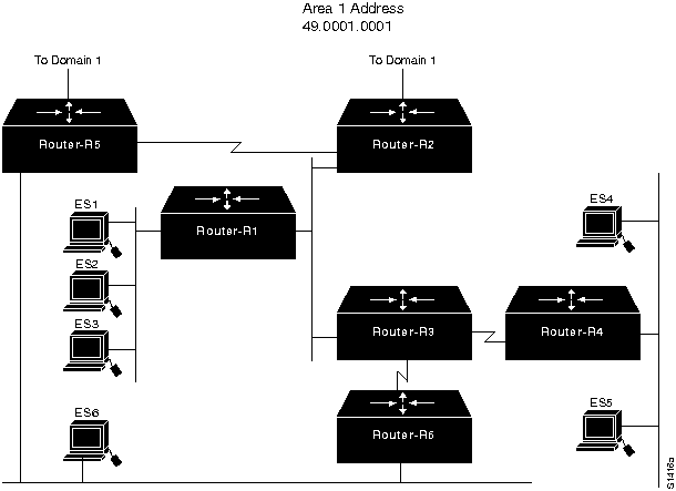
Figure 9-1 illustrates Area 1 of Domain 1 in an ISO CLNS network segment that contains three domains. In Area 1, some end systems cannot communicate with other end systems. The following facts summarize the situation:
- ES1 cannot communicate with ES2, an end system that is on the same network segment.
- ES1 cannot communicate with ES4, an end system that is on a different network segment from ES1 but is in the same area as ES1.
- ES1 cannot communicate with an end system that is outside of area 1 but is in domain 1.
Many times, these symptoms are caused by simple configuration errors, such as inadvertently assigning duplicate addresses. By using debug and management tools, problems can be quickly isolated.
Figure 9-1 : Initial ISO CLNS Connectivity Scenario Map
Environment Description
The relevant elements of the internetworking environment shown in Figure 9-1 can be summarized as follows:
- Area 1 consists of six routers (Router-R1 through Router-R6) and six end systems (ES1 through ES6). End systems ES1 through ES3 are on the same Ethernet segment, ES4 and ES5 share another Ethernet segment, and ES6 is on the same Ethernet segment as Router-R5 and Router-R6.
- Router-R2 and Router-R5 are connected by a point-to-point link. Both routers connect to the domain 1 backbone and are considered Level 2 routers, although in this discussion they participate in both Level 1 and Level 2 routing.
- Router-R3 has a point-to-point connection to Router-R4 and another point-to-point connection to Router-R6.
- The addressing scheme for domain 1, the areas within domain 1, and the systems within area 1 are based on the topology shown in Figure 9-2 and summarized in Table 9-1.
Figure 9-2 : ISO CLNS Scenario Area and Domain Topology Map
.
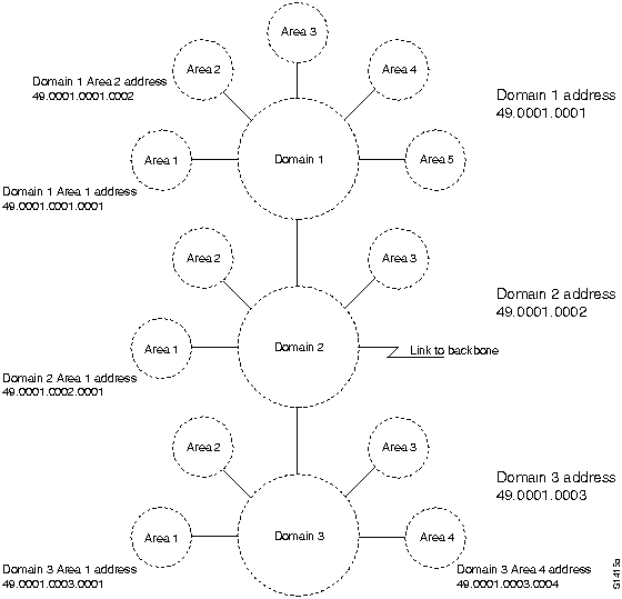
Table 9-1 : Domain 1 Area 1 System IDs
| ES1
|
0000.0000.0001
|
| ES2
|
0000.0000.0002
|
| ES3
|
0000.0000.0003
|
| ES4
|
0000.0000.0004
|
| ES5
|
0000.0000.0005
|
| ES6
|
0000.0000.0006
|
| Router-R1
|
0000.0000.1001
|
| Router-R2
|
0000.0000.1002
|
| Router-R3
|
0000.0000.1003
|
| Router-R4
|
0000.0000.1004
|
| Router-R5
|
0000.0000.1005
|
| Router-R6
|
0000.0000.1006
|
Table 9-1 shows a simplified way of maintaining address consistency within an area. Given the domain 1 and area 1 addresses shown in Figure 9-2, the complete (NSAP) address for ES1 would be the following:
- 49.0001.0001.0001.0000.0000.0001.00
Note that the six-byte system ID and the one-byte n-selector are appended to the domain and area address. Similarly, the NSAP address for Router-R1 would be the following:
- 49.0001.0001.0001.0000.0000.1001.00
Diagnosing and Isolating Problem Causes between ES1 and ES2
The following problems are likely candidates for the first symptom. (ES1 cannot communicate with ES2, a host on the same network segment.)
- ES2 or ES1 does not support an implementation of the End System-to-Intermediate System (ES-IS) protocol that allows the two systems to dynamically discover one another and place the routing entries into the adjacency database.
- Static entries are missing or misconfigured in the end systems.
This list is ordered according to a combination of two criteria: ease of problem determination and the likelihood of being the actual problem. In general, it is useful to eliminate most likely problems first, and then to tackle more complex problems as necessary. The problem-solving process that follows illustrates this strategy.
Once you develop a list of possible problems, analyze each potential cause. The following discussion considers the problems for this scenario.
Checking Adjacency Databases in the End Systems
A number of mechanisms place system entries in adjacency databases. For a description of the various messages that end systems (ESs) and intermediate systems (ISs) use to advertise their presence on the network, see the Internetworking Technology Overview publication. These messages include the following:
- IS hello (ISH) packets
- ES hello (ESH) packets
- Redirect (RD) messages
- Link state packets (LSPs)
Common causes for a missing entry in the adjacency database are end systems that require manual installation of a static entry and end systems that do not fully support the ES-IS protocol, which means that they cannot dynamically discover other systems in the network.
To correct a missing entry in the adjacency database, follow these steps:
Step 1 Look in the adjacency database on each system and verify that addresses exist for the other systems that are directly attached. Create static entries in the adjacency database for the missing NSAP to Subnetwork Point of Attachment (SNPA) mappings.
Step 2 Check the ES-IS implementation on ES1 and ES2. Doing so may require contacting the software supplier or researching the system documentation.
Step 3 Depending on the ES-IS implementation on the end system, you might need to create static entries for other ESs that are on the same physical interface or ISs on the same interface.
If ES1 and ES2 have entries for one another in their adjacency databases, they should be able to directly communicate.
Diagnosing and Isolating Problem Causes Between ES1 and ES4
The following problems are likely candidates for the second symptom. (ES1 cannot communicate with ES4, a host on a different network segment in the same area.)
- Either ES1 or ES4 does not support an implementation of the ES-IS protocol that allows the systems to dynamically discover their intermediate systems (Router-R1 and Router-R4). This problem is described in the section "Checking Adjacency Databases in the End Systems" earlier in this section.
- There is a connectivity problem between ES1 and ES4.
Checking Connectivity from the Router to the End System
The steps that follow focus on using the EXEC trace and show EXEC commands to verify connectivity from the router to the end system. Systematically verify each link in the path.
Step 1 At Router-R1, use the trace EXEC command to verify connectivity to ES4. Based on the network installation map, which should resemble Figure 9-1, you can see that the path to ES4 is through Router-R3 and Router-R4. Use the trace command on the NSAP address for ES4. Figure 9-3 shows an example of the trace command output.
Figure 9-3 : Output from the trace Command

- It is most likely that connectivity problems will occur between ES4 and Router-R4, rather than between the routers.
Step 2 Use EXEC show commands to display the routing table and adjacency database information for the router.
- If you get a response from Router-R3 but not from Router-R4, Router-R4 does not have an entry for ES4. Establish a connection to Router-R4 and display the routing table information.
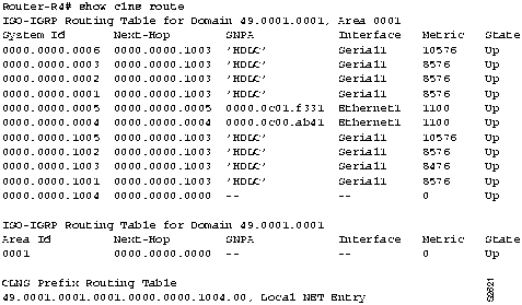
- If you are running ISO-Interior Gateway Routing Protocol (IGRP), use the show clns route EXEC command. (See Figure 9-4.)
Figure 9-4 : Output of the show clns route Command
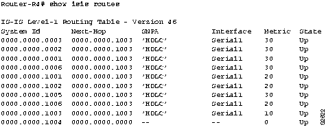
- If you are running IS-IS, use the show isis routes EXEC command. (See Figure 9-5.)
Figure 9-5 : Output of the show isis routes Command
Step 3 Next, use the show clns neighbors command to see whether Router-R4 has adjacency information for ES4. (See Figure 9-6.) If the show clns neighbors EXEC command shows a system ID for ES4 and its SNPA value is valid, there might be a problem with a misconfigured area address as described in the next step.
Figure 9-6 : Output of the show clns neighbors Command

Step 4 Use the show clns neighbors detail EXEC command to show which area address ES4 is advertising in its ESH packets. (See Figure 9-7.) If the area address being advertised is different from that of the area configured for Router-R4, the router has no indication that ES4 is in its area and therefore does not forward packets to it.
Figure 9-7 : Output of the show clns neighbors detail Command

- Correct the area address entry on ES4.
Step 5 If the routing table entry for ES4 shows that it exists, but is on a different network, there are two possibilities: duplicate end system addresses exist within the area, or a routing loop exists. To check on duplicate end system addresses, use the show clns route EXEC command and the show clns neighbors EXEC command at each point in the path to the suspect ES4 until you locate the problem. In the case of a duplicate address that causes another end system to masquerade as ES4, reconfigure the duplicate system to its proper NSAP address.
Step 6 To see if there is a routing loop, you can check the conditions that follow. In general, a routing loop within an area is a transient condition caused by a topology change. However, if a loop persists, use the trace route EXEC command to discover where the loop occurs.
Step 7 If you are running the ISO-IGRP, turn on debugging with the debug clns igrp packet privileged EXEC command. Refer to the Debug Command Reference publication for a description of debug output.
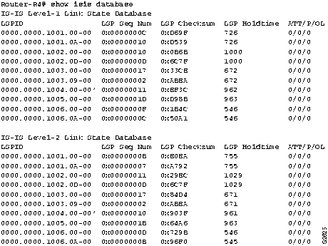
Step 8 If you are running the IS-IS protocol, you can perform a quick check of the LSP databases and verify that they are synchronized, as follows:
- Look at all sequence numbers of all LSPs and see whether they are the same. LSPs are sorted, so it is fairly easy to perform a visual check on the LSP display for each router. Figure 9-8 shows a sample display emphasizing the LSP sequence numbers. This method is suitable for a small network.
Figure 9-8 : Output of the show isis database Command Showing LSP Sequence Numbers
- You can use the debug isis update packets privileged EXEC command and look at the debug output to pinpoint the problem. Refer to the Debug Command Reference publication for a description of debug output.
In IS-IS, use the following procedure to verify that connections exist between the routers and end systems:
Step 1 If the show isis routes EXEC command does not show ES4, yet it appears in the adjacency database displayed by show clns neighbors, there is no connectivity between Router-R4 and the pseudo node. The pseudo node is a fictitious node that reports all the end system and intermediate system nodes on a subnetwork. The node information is present in a pseudo node IS-IS LSP. Router-R4 will have a connection to the pseudo node, which provides a connection to all other reported end systems.
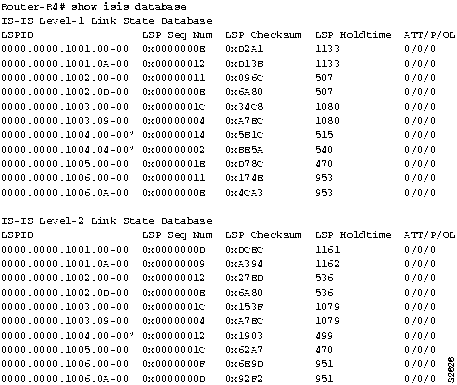
- Use the show isis database EXEC command to verify that Router-R4 is generating both an LSP and a pseudo node LSP, as shown in Figure 9-9.
Figure 9-9 : Output of the show isis database Command Showing LSP and Pseudo Node LSP
Step 2 Next, use the show isis database detail 000.000.0004.01-00 level-1 command to display the contents of the pseudo node for ES4 Level 1 LSP. You are looking for the end system (ES4) to be listed in the LSP of the pseudo node. If the end system does not appear, there is probably a bug in the designated router.
- If you use the clns host global configuration command to map the name ES4 to its associated NSAP address, you can use the name rather than the system ID in the show isis database detail EXEC command. Figure 9-10 shows how the clns host command is used.
Figure 9-10 : Example of the clns host Command

Step 3 If ES4 appears in the pseudo node LSP, verify that Router-R4 appears in the pseudo node LSP, as shown in Figure 9-11.
Figure 9-11 : Output Showing Pseudo Nodes for ES and IS

- The pseudo node advertises all ESs and ISs on the subnetwork. By looking at the command output, you should see that the pseudo node has a link to ES4 and to Router-R4, and that Router-R4 has a connection back to the pseudo node. If all these pieces of the connection exist, there is connectivity between Router-R4 and ES4.
- A pseudo node may exist, but Router-R4 is not yet in the pseudo node LSP because IS-IS was not configured on its Ethernet interface. The reason a pseudo node would exist for Router-R4 is because it may have been flooded through that path through another router.
- Another problem not to be overlooked in this instance is that IS-IS routing was not enabled on RouterR4's Ethernet interface.
Step 4 Continue to work backward from Router-R4. Verify in an LSP from Router-R3 that a connection exists to Router-R4. Verify that Router-R3 has a connection to the pseudo node on the Ethernet shared with Router-R1 (and Router-R2) and that the pseudo node has a connection back to Router-R3, Router-R2, and Router-R1.
Step 5 Verify in the LSP for Router-R1 that it has a connection to the pseudo node in Router-R3. If there is no connection to the pseudo node, verify that the LSP sequence numbers are the same for Router-R1 as they are for Router-R3.
Step 6 After verifying that all the connections exist in the various LSP databases as shown by the show isis database detail level1 EXEC command, connectivity should exist between ES1 and ES4. If there is a topology change---for example, a router is moved or wiring connections are changed---some time can pass before the change is detected, the new LSP is flooded throughout the network, and all the routers and end systems generate new routing tables with the updated information.
Verifying ISO-IGRP Connections
In ISO-IGRP, use the following steps to verify that connections exist between the routers and end systems along the path from ES1 to ES4:
Step 1 Turn on debugging in Router-R3 using the debug clns igrp packet privileged EXEC command and look at the update packets that are coming in from Router-R4. If you see that Router-R4 is advertising ES4, determine why Router-R3 is not putting ES4 in its routing table.
Step 2 At Router-R3, use the trace EXEC command to verify the path back to Router-R1.
Step 3 For each router in the path from Router-R1 to Router-R4, use the show clns routes EXEC command to verify the router is learning the path.
Step 4 After using the debug command, use the no debug clns igrp packets command to turn it off.
Diagnosing Problem Causes between ES1 and an End System outside Its Area
For the third connectivity symptom (ES1 cannot communicate with an end system outside its own area, such as ES8), the problem-solving steps are the same as those in the section "Diagnosing and Isolating Problem Causes Between ES1 and ES4" earlier in this chapter.
- Use the trace EXEC command to address the end system SNPA.
- Verify each link along the path and display the routing table contents by using the show clns route EXEC command (or the show isis routes EXEC command) and the show clns neighbors EXEC command.
End System Problem Solution Summary
This scenario focused on diagnosing end system connectivity problems.
- Misconfigured addresses were corrected.
- Connectivity was verified by displaying adjacency tables (IS-IS) and routing tables (ISO-IGRP).
- Routing for IS-IS or ISO-IGRP was enabled as required.
Figure 9-12, Figure 9-13, and Figure 9-14 provide representative configuration listings for routers discussed in this scenario.
Figure 9-12 : Partial Configuration Listing for Router-R1

Figure 9-13 : Partial Configuration Listing for Router-R3
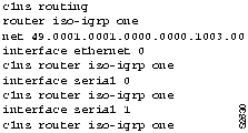
Figure 9-14 : Partial Configuration Listing for Router-R4

ISO CLNS Connectivity over WANs
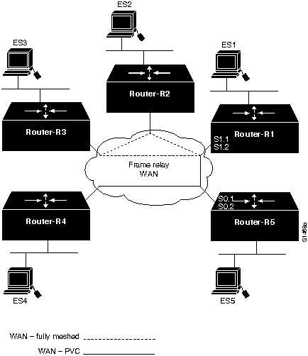
Figure 9-15 illustrates various subnetworks that communicate through a Frame Relay cloud. The following facts summarize the situation:
- End system ES1 cannot communicate with ES2, an end system that is reached through the WAN, but is part of a fully meshed, logical network.
- ES4 cannot communicate with ES5, an end system that is reached through a permanent virtual circuit (PVC) on a subinterface.
- ES4 cannot communicate with ES1, an end system that is reached through ES5 and relies on subinterfaces and PVCs on both Router-R5 and Router-R1.
Figure 9-15 : ISO CLNS Communication through a WAN Using Subinterfaces and PVCs
Environment Description
The relevant elements of the internetworking environment shown in Figure 9-15 can be summarized as follows:
- Router-R1, Router-R2, and Router-R3 are fully meshed and participate in multiaccess, broadcast communication.
- Router-R1 uses subinterfaces on its physical port S1 to communicate with the meshed network (S1.1) and to provide a PVC to Router-R5 (S1.2). A subinterface is occasionally referred to as a "virtual interface" or a "virtual port."
- Router-R5 uses subinterfaces on its physical port S0 to provide two PVCs: one to Router-R1 (S0.1) and one to Router-R4 (S0.2).
- Router-R1 and Router-R4 cannot communicate directly, but must have their packets forwarded by Router-R5.
Diagnosing and Isolating Problem Causes between ES1 and ES2 over a WAN
Given the situation, a number of problems might explain connectivity symptoms.
The following problems are likely candidates for the first symptom. (ES1 cannot communicate with ES2, a host reached through the WAN.)
- One of the routers (Router-R1 or Router-R2) does not have an entry in the adjacency database because the routers have missing or incorrect frame-relay map interface configuration commands.
- ES1 or ES2 does not support an implementation of the ES-IS protocol that allows the two systems to dynamically discover one another and place the entries into the adjacency database.
- Static entries are missing or misconfigured in the end systems.
IS-IS and ISO-IGRP protocols treat WANs as if they are multiaccess broadcast networks. In this situation, where a meshed network exists between the end systems, the routing protocol looks at the WAN as if it was a "solid wire" network like Ethernet. Other than the addition of frame-relay map commands in the routers, verifying ES-to-ES connectivity is the same as described in the section "Diagnosing and Isolating Problem Causes between ES1 and ES2," earlier in this chapter.
The information that follows explores the router as the cause of the connectivity problem.
Checking for Missing or Incorrect map Commands
A common cause for a missing entry in an adjacency database on the router is a missing or incorrect frame-relay map command. Assume the Data Link Connection Identifier (DLCI) values for routers are as shown in the following list:
- Router-R1: DLCI 16 to R2
- Router-R1: DLCI 17 to R3
- Router-R1: DLCI 18 to R4
- Router-R2: DLCI 21to R1
- Router-R2: DLCI 23 to R3
- Router-R3: DLCI 31 to R1
- Router-R3: DLCI 32 to R2
Step 1 If you are running ISO-IGRP, look in the adjacency database on each router and verify that entries exist for the other router that is accessed through the Frame Relay WAN. Use the show clns neighbors EXEC command to display the adjacency information, as shown in Figure 9-16.
Figure 9-16 : Output of the show clns neighbors Command

Step 2 If the adjacency information is missing, check the router configuration and look for missing or incorrect frame-relay map commands. The frame-relay map commands are required whether you are running ISO-IGRP or IS-IS over the router interface.
- At Router-R1 you must have interface configuration commands on the port that provide the connection to the WAN. For the DLCI values in this scenario, the commands would be the following.
interface serial 1
encapsulation frame-relay
interface serial 1.1 multipoint
frame-relay map clns 16 broadcast
frame-relay map clns 17 broadcast
interface serial 1.2
frame-relay interface-dlci 19
- Similarly, Router-R2 must have interface configuration commands that point to Router-R1 and Router-R3.
frame-relay map clns 21 broadcast
frame-relay map clns 23 broadcast
- And Router-R3 must have interface configuration commands that point to RouterR1 and Router-R2.
frame-relay map clns 31 broadcast
frame-relay map clns 32 broadcast
Step 3 Verify that ISO-IGRP or IS-IS routing is enabled for the router interface with the clns router iso-igrp or clns router isis interface configuration command on each router.
Note The IS-IS implementation differs slightly from the OSI specification in that in a multiaccess network, the Frame Relay WAN is treated as though it were a "solid wire" network like Ethernet. Designated router election is run over a Frame Relay network, and the designated router will have a pseudo node entry for the Frame Relay network. The same concepts of pseudo nodes and pseudo node links over an Ethernet described in the section "Checking Connectivity from the Router to the End System," earlier in this chapter, applies to problem diagnosis over a Frame Relay network.
- If Router-R1 and Router-R2 have entries for one another in their adjacency databases, they should be able to communicate.
Diagnosing Problem Causes between ES4 and ES1 over a WAN
Several problems can cause connectivity symptoms between ES4 and ES1:
- The subinterfaces on Router-R5 that provide PVCs to Router-R4 and Router-R1 might be misconfigured.
- The subinterfaces on Router-R1 that provide connections to Router-R5 and to the meshed logical network that includes Router-R2 and Router-R3 might be misconfigured.
- There is a connectivity problem between Router-R1 and Router-R4.
Checking the Subinterface Configuration on Router-R5
A single physical interface can provide more than one connection by means of virtual interfaces, commonly called "subinterfaces." Subinterfaces are configured the same as interfaces and use the same set of interface configuration commands.
Assume that the DLCI values for Router-R4 and Router-R5 for routers are as follows:
- Router-R4: DLCI 45 to R5
- Router-R5: DLCI 51 to R1
- Router-R5: DLCI 54 to R4
Step 1 For Router-R5, verify that the configuration commands for interface serial 0, its physical interface to the WAN, include the commands that follow:
interface serial 0.1
clns router isis
! Or clns router iso-igrp
frame-relay map clns 51
interface serial 0.2
clns router isis
!Or clns router iso-igrp
frame-relay map clns 54
!PVC commands for R5 subinterfaces serial 0.1 and serial 0.2 follow.
interface serial 0
encapsulation frame-relay
interface serial 0.1 point-to-point
frame-relay interface-dlci 51
interface serial 0.2 point-to-point
frame-relay interface-dlci 54
Checking the Subinterface Configuration on Router-R1
On Router-R1, interface serial 0 provides two subinterfaces: an interface to the multiaccess network and an interface to the point-to-point PVC from Router-R5. To check the subinterface configuration, verify that the configuration commands for interface serial 1 of Router-R1 (its physical interface to the WAN), include the following commands:
interface serial 1.1 multipoint
clns router isis
!(OR clns router iso-igrp)
frame-relay map clns 12
frame-relay map clns 13
interface serial 1.2 point-to-point
clns router isis
!(OR clns router iso-igrp)
frame relay interface-dlci 1
- The multipoint subinterface running IS-IS is treated as a multiaccess broadcast router. The point-to-point subinterface is treated as a "real" serial link, and the point-to-point IS-IS protocol is run on that link.
Checking Connectivity between Router-R1 and Router-R4
The following procedure for checking connectivity between Router-R1 and Router-R4 over a WAN is similar to the procedure for checking connectivity in which no WAN is involved:
Step 1 Use the ping EXEC command between Router-R1 and Router-R4 to verify that traffic is going through the WAN. Figure 9-17 illustrates output from the ping command.
Figure 9-17 : Output from the ping Command

Step 2 Use the trace EXEC command to verify connectivity from Router-R4 to Router-R5 and from Router-R5 to Router-R1, as shown in Figure 9-18.
Figure 9-18 : Output from the trace Command

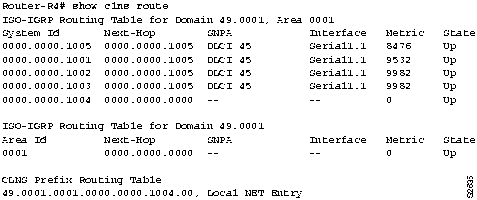
Step 3 Use EXEC show commands to display the routing table and adjacency database information for the routers. Figure 9-19 and Figure 9-20 illustrate the show command output for ISOIGRP and IS-IS.
- If you are running ISO-IGRP, use the show clns route EXEC command.
Figure 9-19 : Output of the show clns route Command
- If you are running IS-IS, use the show isis routes EXEC command.
Figure 9-20 : Output of the show isis routes Command

Step 4 Check the adjacency database entries by using the show clns neighbors and show clns neighbors detail EXEC commands to verify that the correct area address information is being advertised and that the routers contain entries in their adjacency databases.
Step 5 If there are no adjacency database entries, verify that the frame relay map interface configuration commands are correct for each interface or subinterface.
Step 6 If the show isis routes command does not show Router-R5, yet it appears in the adjacency database, there may be a problem in the IS-IS LSP. Use the show isis database EXEC command to verify that the LSPs between the routers point to one another and that they are synchronized.
Step 7 For ISO-IGRP, use the debug clns igrp privileged EXEC command to verify that the routers are receiving advertised routes.
After you correct the problems with the adjacencies and routes, you should have connectivity.
ISO CLNS Route Redistribution Loops
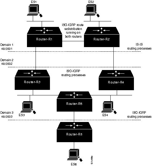
Figure 9-21 shows three domains, two of which are running ISO-IGRP and one that is running ISIS. Domain 1 runs IS-IS routing processes internally, while routers R1 and R2 redistribute IS-IS and ISOIGRP routes. Domain 2 and domain 3 run ISO-IGRP routing processes. To summarize the situation, a routing loop exists between Router-R1 and Router-R2 that blocks traffic between domain 1 and domain 3.
Environment Description
The relevant elements of the internetworking environment shown in Figure 9-21 can be summarized as follows:
- Domain 1 has two Level 1 and Level 2 border routers that perform route redistribution between ISIS and ISO-IGRP.
- Domain 2 and domain 3 are running ISO-IGRP.
Figure 9-21 : Route Redistribution Loops
Diagnosing and Isolating Route Redistribution Loops
This section describes how routing loops can occur in the topology shown in Figure 9-21, and gives specific recommendations for eliminating routing loops.
Initially, the redistributing routers (Router-R1 and Router-R2) have 49.0001 in their routing tables as an IS-IS route. This route is redistributed into ISO-IGRP, which causes 49.0001 to be advertised into domain 49.0002 at two points. The 49.0001 advertisement propagates throughout domain 49.0002 and returns to the redistributing routers. By default, the redistributing routers place the ISO-IGRP route in their routing tables with a next-hop pointing outside of the domain toward 49.0002. This pointer is erroneous because 49.0001 cannot be reached directly through domain 49.0002.
When an ES in domain 49.0002 originates a packet to an ES in 49.0001, the packet reaches one of the redistributing routers, which attempts to forward the packet back to domain 49.0002. A packet-forwarding loop occurs, and the packet is never delivered.
The manner in which the routing algorithms are run gives preference to ISO-IGRP routes over ISIS routes when default route metrics are used. Because RouterR1 and RouterR2 both advertise an ISO-IGRP route to 49.0003, packets from 49.0001 (domain 1) to 49.0003 get caught in a loop because RouterR1 and RouterR2 use the preferred ISO-IGRP route to 49.0003 rather than the IS-IS route. That is, RouterR1 has a choice of sending a packet to 49.0003 through the ISOIGRP route from RouterR3, or through the ISIS route that has been redistributed by RouterR2. It chooses the ISO-IGRP route. RouterR2, upon receiving the packet faces the same choice of routes: ISO-IGRP to RouterR1 or IS-IS to Router4. The packet never escapes this loop.
To prevent a route redistribution loop, you must make the IS-IS route win at RouterR2 and lose at RouterR1 by setting the administrative distance so that the IS-IS route is preferred. The steps that follow describe how to verify that a routing loop exists and how to correct it by modifying the router configuration:
Step 1 Use the trace route EXEC command to discover where the loop occurs.
Step 2 Use the show isis database EXEC command to display the LSP database and look at the routes in the suspect loop.
Step 3 Use the debug isis update packets privileged EXEC command and look at the debug output to pinpoint the problem. Refer to the Debug Command Reference publication for a description of debug output.
Step 4 After you find and verify the route redistribution loop, change the configuration of RouterR2 so that its IS-IS route to 49.0003 is preferred over the ISO-IGRP route back to RouterR1. Figure 9-22 shows the commands that resolve the routing loop.
Figure 9-22 : Router Configuration That Resolves Routing Loop
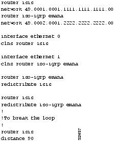
- Add the distance metric as shown. The administrative distance of 90 for the IS-IS process in RouterR2 assures its precedence over the ISO-IGRP route back to RouterR1. Packets received by RouterR1 for 49.0003 are sent to Router-R2, where they are sent on to their destination, eliminating the routing loop.
DECnet Phase IV and Phase V Connectivity
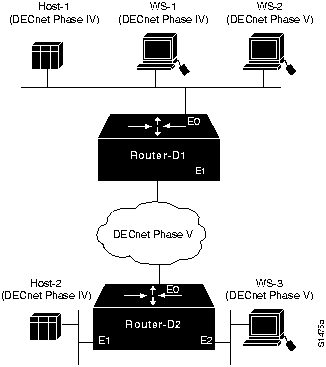
Figure 9-23 illustrates a network that consists of both DECnet Phase IV and DECnet Phase V nodes. Some Phase IV nodes communicate through a DECnet Phase V cloud; others rely on DECnet Phase IV-to-Phase V conversion performed in the router. The following facts summarize the situation:
- The DECnet Phase IV node Host-1 cannot communicate with the DECnet Phase IV node Host2 through the DECnet Phase V cloud.
- The DECnet Phase IV node WS-1 cannot communicate with the DECnet Phase V node WS3.
Figure 9-23 : DECnet Phase IV and Phase V Network
Environment Description
The relevant elements of the internetworking environment shown in Figure 9-23 can be summarized as follows:
- Router-D1 and Router-D2 perform DECnet Phase IV-to-Phase V conversion on all interfaces.
- All routers and nodes are in the same area.
- Other systems that make up the DECnet Phase V cloud are not relevant to the communication problems described in the scenario.
Diagnosing and Isolating Problem Causes for DECnet Phase IV Connectivity through a Phase V Cloud
The following problems are potential causes for the first symptom. (Two DECnet Phase IV nodes cannot communicate through a DECnet Phase V cloud.)
- DECnet conversion has not been enabled on the interfaces.
- The conversion prefix, which is required for packet conversion, is specified incorrectly.
- The DECnet Phase IV nodes are not configured to be in the same area.
- There is a connectivity problem.
In general, it is useful to eliminate most likely problems first and then to tackle more complex problems as necessary. The problem-solving process that follows illustrates this strategy.
Checking DECnet Conversion Processes and Prefixes on the Interface
In order for a DECnet Phase IV packet to pass through a DECnet Phase V cloud, DECnet conversion must be enabled on all router interfaces in the path, and the conversion prefixes must be specified correctly.
Use the following procedure to check the configuration of DECnet conversion prefixes:
Step 1 Use the write terminal EXEC command to list the configuration of the router. Verify that both ISO CLNS routing and DECnet routing are enabled on the router.
Step 2 Check that the network command correctly specifies the DECnet routing process node ID. You must enter, in hexadecimal, the byte-swapped address for the Phase IV-to-Phase V conversion address.
- For example, the decimal Phase IV-to-Phase V conversion address 20.401 is converted as follows: (20 * 1024) + 401 = 20,881. The hexadecimal value of 20,881 is 5191. When the bytes are swapped, it becomes 9151. Figure 9-24 includes an example of the network command.
Figure 9-24 : DECnet Conversion Commands
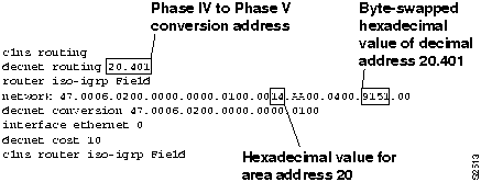
Step 3 Verify that the DECnet area ID is correctly converted to its hexadecimal value; in this case DECnet area 20 (decimal) equals 14 (hexadecimal).
Step 4 Use the debugging commands debug decnet routing and debug clns packet at Router-D1 to observe the Phase IV packet getting converted to Phase V (at Router-D1), going through the Phase V cloud, and reaching Router-D2, where it is converted back to Phase IV.
Checking Area Addresses
One of the requirements for DECnet Phase IV-to-Phase V conversion is that the DECnet node, which is an ES, and the converting router, which is an IS, must be in the same area. If the ES and IS are in different areas, no conversion takes place.
Use the following procedure to check area addresses:
Step 1 Use the show decnet route EXEC command to display the DECnet routing tables. The area ID for the DECnet node and for the router must be the same, as shown in Figure 9-25.
Figure 9-25 : Output of the show decnet route Command

Step 2 If the area IDs do not match, verify that the DECnet-to-CLNS address conversion was done correctly, or reconfigure the router with an area address that matches the DECnet host.
Step 3 Use the show clns neighbors EXEC command to display the CLNS adjacency database. This command shows the addresses of all CLNS neighbors and can indicate area address problems with adjacent systems.
Step 4 Use the show clns route EXEC command to display the CLNS routes. This command is useful when the routers are not adjacent. You should see an address entry for the Phase IV router. If not, proceed to the next section, "Checking Connectivity."
Checking Connectivity
After checking the most common problems (incorrect DECnet-to-CLNS address conversion and different area IDs for the DECnet host and the router), verify the connectivity between the routers and the hosts.
Use the following procedure to check connectivity:
Step 1 Use the ping EXEC command to see whether connectivity can be established between RouterD1 and Host2 through the DECnet Phase V cloud, as shown in Figure 9-26.
Figure 9-26 : Output of the ping Command for DECnet Phase IV
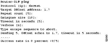
Step 2 By using a combination of the show clns route, show clns neighbors, and show decnet route EXEC commands to display routing information and the ping command to check connectivity, you can quickly locate and diagnose connectivity problems.
Step 3 Correct any addressing errors or router configuration errors that you find.
Diagnosing and Isolating Problem Causes for DECnet Phase IV-to-Phase V End Systems
The following problems are potential causes for the second symptom. (A DECnet Phase IV node cannot communicate with a DECnet Phase V node.)
- The DECnet Phase V system ID is not compatible with DECnet Phase IV.
- DECnet conversion must be enabled on the interfaces.
Checking System IDs
DECnet Phase IV allows a maximum of 63 system IDs, numbered 1 through 63. When a DECnet Phase IV node communicates with a DECnet Phase V node, no problem exists for the system ID conversion. However, DECnet Phase V allows more than 63 system IDs, which causes problems if the node tries to communicate with a DECnet Phase IV node.
Use the following procedure to check system IDs:
Step 1 At the DECnet Phase V node, check the system ID entry in the CLNS address of the node. If it is larger than 3F hexadecimal (63 decimal), it cannot communicate with a DECnet Phase IV node.
Step 2 If necessary, reconfigure the system ID of the DECnet Phase V node to a value of 63 or less.
Checking DECnet Conversion
The conversion problems that you might encounter when a Phase IV system communicates with a Phase V system are nearly identical to those you might encounter when a Phase IV system communicates through a Phase V cloud.
Use the following procedure to verify that DECnet conversion is configured correctly:
Step 1 Check the router configuration and verify that both DECnet and CLNS routing processes are enabled.
Step 2 Verify that the host (ES) and the router (IS) that are performing the conversion are in the same area.
Step 3 Check that the DECnet Phase IV decimal addresses are correctly converted and entered in the byte-swapped hexadecimal conversion format.
Step 4 Use the show clns route, show clns neighbors, and show decnet route EXEC commands to display routing information and verify that the routes are being propagated.
Step 5 Use the ping EXEC command to verify connectivity throughout the path.
Problem Solution Summary
This scenario focused on diagnosing DECnet Phase IV-to-Phase V conversion problems. The solutions included the following:
- Conversion prefixes were verified for proper Phase IV decimal notation to Phase V byte-swapped hexadecimal notation.
- Router commands that enable the conversion processes were verified.
- Area addresses for ES to IS conversion were checked to make certain both systems were in the same area.
- System IDs were verified for DECnet Phase IV-to-Phase V compatibility, where a Phase V host communicates with a Phase IV host.
Figure 9-27 and Figure 9-28 provide representative configuration listings for routers discussed in this scenario.
Figure 9-27 : Relevant DECnet Phase IV-to-Phase V Conversion Configuration for Router-D1
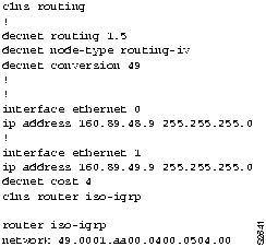
Figure 9-28 : Relevant DECnet Phase IV-to-Phase V Conversion Configuration for Router-D2
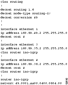
NCR/AT&T StarGroup Considerations
This section provides a configuration example that illustrates issues that are specific to the NCR/AT&T StarGroup implementation of ISO CLNS. In this example, three routers connect two areas via serial interfaces. Figure 9-29 represents the topology of the network.
Figure 9-29 : StarGroup Topology Example

Note Putting each router in its own area (for a total of three) would reduce the number of routing updates sent across the serial lines.
Figure 9-30 shows the configuration for Router LeftCoast.
Figure 9-30 : Configuration for Router LeftCoast
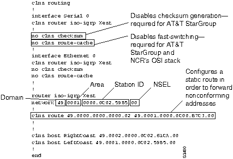
Because of a problem in the AT&T StarGroup checksum calculation, checksum generation must be disabled on the router. Use the no clns checksum interface configuration command to disable checksum generation on the router.
Fast switching must be disabled as well, because the Cisco router will pad odd-length packets when fast switching. Both the AT&T StarGroup and the NCR ISO CLNS protocol stacks will discard packets in which the value of the 802.3 length field no longer matches the length calculated from the header information. Padding packets while fast switching causes this value to change, resulting in packet drops. Use the no clns route-cache interface configuration command to disable fast switching.
Note The AT&T StarGroup implementation requires that the station ID portion of the NSAP (see Figure 9-30) match the MAC address of that station. In order to interoperate, the Cisco router must make the same requirement. However, this is generally neither a Cisco nor an ISO requirement.
Another consideration when using the AT&T StarGroup implementation is the necessity of using the clns route global configuration command. StarGroup uses a 16-octet NSAP, which does not follow the ISO 8348/AD2 specification, in order to preserve backward compatibility with earlier versions of StarGroup. The clns route command, by configuring a static route, ensures that the router passes packets using the older StarGroup NSAP address prefix to the next neighbor in the path (in this case, NoCoast).
Figure 9-31 shows the output of the show clns route EXEC command for Router LeftCoast. This command displays all of the destinations to which the router knows how to route packets. Note that the static route entry shows the nonconforming NSAP (that is, the 16-octet NSAP) used by older StarGroup software. The show clns route command is useful in determining the next-hop router and whether static routes have been configured. (For more information on the various fields in the show clns route command, see the Router Products Command Reference publication.)
Figure 9-31 : show clns route Command Output for Router LeftCoast
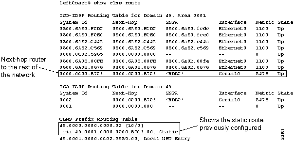
Figure 9-32 shows the output of the show clns es-neighbors detail EXEC command for Router LeftCoast. This command shows the table constructed by the router from Hellos sent by its end system neighbors. The detail keyword must be included if you want to see NSAP information for nonconforming neighbors.
Note The station ID and the system ID noted in Figure 9-32 actually match, but are parsed differently because they are StarGroup nonconforming NSAPs.
The show clns es-neighbors detail command also shows the statically defined NetBIOS Directory User Agent (NDUA) station ID. The NDUA is a special station ID and function as a sort of name-server for StarGroup. There must be at least one primary NDUA configured for each area.
Figure 9-32 : show clns es-neighbors detail Command Output for Router LeftCoast

The configuration for Router NoCoast is shown in Figure 9-33. As was done with Router LeftCoast, static routes are configured to ensure that nonconforming StarGroup addresses are forwarded properly.
Figure 9-33 : Configuration for Router NoCoast
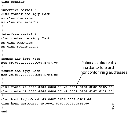
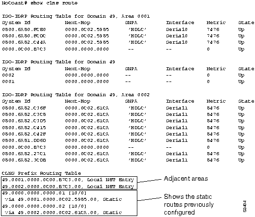
Figure 9-34 shows the output from the show clns route EXEC command. Note that adjacent areas and the static routes configured on the router appear in the routing table.
Figure 9-34 : show clns route Command Output for Router NoCoast
The configuration for Router RightCoast is basically the reverse of Router LeftCoast.
NCR/AT&T StarGroup X.25 Encapsulation
When you choose X.25 encapsulation, you must manually enter the NSAP-to-X.121 address mapping. Assume that two routers, Router-A and Router-B, are communicating over an X.25 link through their serial interfaces. Configuration commands for interface serial 0 on Router-A are as follows:
interface serial 0
encapsulation x25
x25 address 777777022
clns router static area0099
no clns checksum
Replace the X.25 address in this example with your address.
Note When multiple switched virtual circuits are established between two routers, the packets can arrive out of sequence. Out-of-sequence packets will cause excessive delay. Use the x25 nvc 1 interface configuration command to limit the number of virtual circuits that can be established between hosts.
Because no routing updates are sent over an X.25 link, the remainder of the interface configuration commands for Router-A define the address of Router-B and establish a static route:
clns is-neighbor 49.0001.0000.0c00.1b87.00 7777770020
clns route 49.0001 49.0001.0000.0c00.1b87.00
clns route 49.0000.0000.0000.01 49.0001.0000.0c00.1b87.00
Interface configuration commands for Router-B are as follows:
interface serial 0
encapsulation x25-dce
x25 address 777777020
clns router static area01
no clns checksum
clns is-neighbor 49.0099.0000.0c00.029e.00 7777770022
clns route 49.0099 49.0099.0000.0c00.029e.00
clns route 49.0000.0000.0000.99 49.0099.0000.0c00.029e.00
Note When you are configuring X.25 encapsulation on a serial interface, the interfaces must maintain a Data Communications Equipment (DCE)/Data Terminal Equipment (DTE) relationship. You must specify one router interface, such as interface serial 0 on Router-B, as DCE. Alternatively, if you use a switch to connect two routers, the switch presents a DCE interface to each router, and Router-A and Router-B are configured with DTE interfaces.
ISO CLNS Connectivity Symptoms
ISO CLNS connectivity symptoms are discussed in the following sections:
Note The symptoms that follow are generic in nature; however, discussions of host configuration problems assume that the host is a UNIX system. Equivalent kinds of actions may also be applicable to non-UNIX hosts, but the discussions do not address non-UNIX end station problems.
Host Cannot Communicate with Offnet Hosts
Symptom: Host cannot communicate with a host on another network. Attempts to make a connection to an intervening router might not be successful. Table 9-2 outlines possible causes and suggested actions when a host cannot communicate with offnet hosts.
Table 9-2 : ISO CLNS: Host Cannot Communicate with Offnet Hosts
| No default gateway
|
Step 1 Determine whether a default gateway is included in the adjacency table of the host attempting to make a connection (Host-A). Use the following UNIX command:
- netstat -rn
Step 2 Inspect the output of this command for a default gateway specification.
Step 3 If the specified default gateway is incorrect, or if it is not present at all, you can change or add a default gateway using the following UNIX command at the local host:
- route add default address 1
- (The value of address is the ISO CLNS address of the default gateway; a value of 1 indicates that the specified node is one hop away.)
Step 4 To automate the addition of a default gateway as part of the boot process, specify the ISO CLNS address of the default gateway in the following file on the UNIX host:
- /etc/defaultrouter
|
| End system has no Level 1 router
|
Step 1 Use the show clns neighbors detail EXEC command to show all end systems (ESs) and intermediate systems (ISs) to which the router is directly connected.
Step 2 Make sure that there is at least one Level 1 router on the same network as the end system.
|
| Level 1 router or ES has bad address
|
Step 1 At the Level 1 router, verify that it has the same address as the end system.
Step 2 Verify that all bytes of the NSAP address, up to but not including the system ID, are the same on both the router and the ES. The domain and area addresses must match, and the station IDs must be unique. The value of the n-selector byte has no impact.
|
| End system host is not running ES-IS protocol
|
Step 1 Use appropriate host commands to verify that an ES-IS process is running. If necessary, initiate the ES-IS process.
Step 2 Check the adjacency database on the host and verify that it has an entry for its directly connected router.
Step 3 Use the debug clns packet privileged EXEC command to verify that the router sees and forwards the packet.
Step 4 If necessary, statically configure the router to recognize the ES by using the clns es-neighbor interface configuration command.
|
| Router between hosts is down
|
Step 1 Use the trace EXEC command to check connectivity between a router and an end system.
Step 2 If the trace fails at a router, use the show clns neighbors EXEC command to see which neighboring routers and ESs are recognized.
Step 3 If neighboring routers and end systems are up, perform one of the following procedures:
- For ISO-IGRP, check the routing table and see whether the routes are being learned. Use the show clns route EXEC command to display the routing tables.
- For IS-IS, check the LSP database to see whether the links are being reported in link state advertisements, then check the IS-IS routing table to see whether the routes are being installed in the routing table. Use the show isis database detail EXEC command to display the routing tables.
|
Host Cannot Access Certain Hosts in Same Area
Symptom: A host cannot access other hosts in the same area. The host is either on the same network or on a different network in the same area, but is unable to establish connectivity. Some networks might be accessible. Table 9-3 outlines possible causes and suggested actions when a host cannot access certain hosts in the same area.
Table 9-3 : ISO CLNS: Host Cannot Access Hosts in Same Area
| Area address is configured incorrectly on the host
|
Step 1 Check all Level 1 routing tables and link state databases.
Step 2 Verify that the hosts are in the same area.
Step 3 Check that the NSAP address is entered correctly on the hosts.
|
| Different area addresses are merged into a single area, but the router is configured incorrectly
|
Step 1 See whether your configuration includes multiple area addresses.
Step 2 Verify that the router is configured to support a multihomed area, which is a single area that has more than one area address.
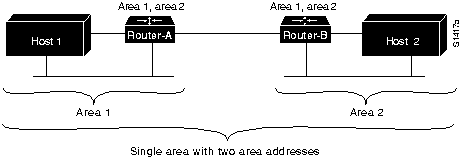
Step 3 Figure 9-35 shows an example of a multihomed area.
- In order to communicate, two routers must establish Level 1 adjacency.
- For area 1 and area 2 to be considered a single area, Router-A must be configured to be in area 1 and area 2. Router-B can be configured in both areas as well.
Step 4 Alternatively, one router can be configured in both areas, while the other router remains configured for a single area. For example, Router-A is in both area 1 and area 2, while Router-B is in area 2 only. Area addresses must overlap to create Level 1 adjacency and establish connectivity.
|
| End system host is not running ES-IS protocol
|
Step 1 See Table 9-2 for suggested actions.
|
| Router between hosts is down
|
Step 1 See Table 9-2 for suggested actions.
|
Figure 9-35 : Multiple Area Addresses in a Multihomed Area
Host Cannot Access Certain Hosts in Different Area
Symptom: A host cannot access a host in a different area. The host tries to access another host that is not in its adjacency database or link state database by going through a Level 2 router. Table 9-4 outlines possible causes and suggested actions when a host cannot access hosts in a different area.
Table 9-4 : ISO CLNS: Host Cannot Access Hosts in Different Area
| Host is not really in a different area
|
Step 1 Verify that the hosts are in different areas.
Step 2 Verify that the host is not part of a multihomed area.
Step 3 Reenter the host address and specify the correct area.
|
| Level 2 routers are not routing packets to the correct area
|
Step 1 Verify connectivity to the border of the area. Use the trace command to verify that Level 1 routers are routing packets to the nearest Level 2 router.
Step 2 Verify that the Level 2 routers are routing packets to the correct area. Use the trace EXEC command to check Level 2 routing.
Step 3 Check the Level 2 topology by inspecting the Level 2 routing tables (ISO-IGRP) or the Level 2 link state databases (IS-IS) to see that the routing is to the correct area.
Step 4 If necessary, reconfigure the router(s) with the correct area addresses and Level 2 (IS-IS) routing information.
|
| End system host is not running ES-IS protocol
|
Step 1 See Table 9-2 for suggested actions.
|
| Router between hosts is down
|
Step 1 See Table 9-2 for suggested actions.
|
Users Can Access Some Hosts but Not Others
Symptom: Users cannot access certain hosts that should be available. This type of problem results from router or host configuration errors or from a router that is down. For troubleshooting guidelines, refer to the sections "Host Cannot Communicate with Offnet Hosts," "Host Cannot Access Certain Hosts in Same Area," and "Host Cannot Access Certain Hosts in Different Area," earlier in this chapter.
Some Services Are Available While Others Are Not
Symptom: In some cases, you might be able to get through to hosts using some protocols, but cannot get through using others. Table 9-5 outlines possible causes and suggested actions when some services are available while others are not.
Table 9-5 : ISO CLNS: Some Services Are Available While Others Are Not
| Host is not configured to support the service
|
Step 1 Verify that the needed services are running on the host system.
|
| Misconfigured access list
|
Step 1 Use the trace EXEC command to determine the path taken to reach remote hosts.
Step 2 (Optional) On each router in the path, enable the debug clns routing privileged EXEC command.
- Any router that returns "unreachables" is suspect.
Step 3 If you can verify the router that is stopping traffic, use the write terminal privileged EXEC command to see whether an access list is being used. You also can use the show access-lists and show clns interface EXEC commands in combination to determine whether access lists are being used.
Step 4 Disable the access list.
Step 5 See whether traffic can get through the router.
Step 6 If traffic can get through, carefully review the access list and its associated commands for proper authorization. In particular, look for an ISO port configured in the access lists.
Step 7 If ports are specified, be sure that all needed ports are explicitly permitted by access lists.
Step 8 Enable the access list and verify reachability of service.
|
Users Cannot Make Any Connections when One Parallel Path Is Down
Symptom: In configurations featuring multiple paths between networks, when one of the parallel links breaks, there is no communication through the alternative routes.
Note IS-IS has equal-cost load balancing for both Level 1 and Level 2 routes. If there are parallel paths in an IS-IS network and one goes down, the other is available as a "hot backup"; that is, it is ready to be used immediately.
Table 9-6 outlines possible causes and suggested actions when users cannot make connections over a parallel path.
Table 9-6 : ISO CLNS: Users Cannot Make Connections over Parallel Path
| Discontinuous network due to failure
|
Step 1 Restore the link.
|
| Routing has not yet converged
|
Step 1 Examine the routing tables for routes listed as "possibly down." This entry indicates that the routing protocol has not converged.
Step 2 Wait for the routing protocol to converge. Examine the routing table later.
- ISO-IGRP only does load balancing for domain prefix routes. If you are doing Level 1 or Level 2 routing in ISO-IGRP, only a single path is maintained. If that path goes down, you must wait for convergence before the alternative path is available.
|
| Misconfigured access lists or other routing filters
|
Step 1 Check for access lists in the path.
Step 2 If present, disable and determine whether traffic is getting through.
- If traffic is getting through, access lists and accompanying commands are probably causing traffic stoppage.
Step 3 Evaluate and modify access lists as necessary.
|
| Errors on serial link
|
Step 1 If the link is a serial link, look for input on the interface by using the show interfaces serial EXEC command.
Step 2 Refer to the discussions regarding serial line debugging in Chapter 3, "Troubleshooting Serial Line Problems," and
Chapter 1, "Troubleshooting Overview," for more information.
|
| Errors on Ethernet link
|
Step 1 Use a time domain reflectometer (TDR) to find any unterminated Ethernet cables.
Step 2 Check host cables and transceivers to determine whether any are incorrectly terminated, overly long, or damaged.
Step 3 Look for a jabbering transceiver attached to a host; this might require a host-by-host inspection.
|
| Nonfunctional FDDI ring
|
Step 1 Use the show interfaces fddi EXEC command to determine status of the interface.
Step 2 If show interfaces fddi EXEC indicates that the interface and line protocol are up, use the ping clns EXEC command between routers to test connectivity to routers.
Step 3 If the interface and line protocol are up, make sure that the addresses of upstream and downstream neighbors are as expected.
- If all zeros appear in either of the address fields for these neighbors, a physical connection problem is likely.
Step 4 In this case (or if status line does not indicate that interface and line protocol are up), check patch-panel connections. Use an optical TDR or light meter to check connectivity between routers; ensure that signal strength is within specification.
|
| Nonfunctional Token Ring backbone
|
Step 1 Use the show interfaces token EXEC command to determine status of the interface.
Step 2 If the status line indicates that the interface and line protocol are not up, check the cable from router to the Multistation Access Unit (MAU). Make sure that the cable is good; replace if necessary.
Step 3 If show interfaces token indicates that the interface and line protocol are up, use the ping clns EXEC command between routers to test connectivity to them.
Step 4 If the remote router does not respond, check the ring speed specification on all systems attached to the Token Ring backbone. Ring speed must be the same for all.
Step 5 If necessary, modify ring speed specifications for the ES and routers.
Step 6 Use the ring-speed interface configuration command to modify ring speed configuration for Token Ring cards that support software speed configuration. Change jumpers as needed for modular router platforms. For more information about ring speed specifications, refer to the hardware installation and maintenance documentation for your system. For additional hints on solving Token Ring problems, refer to the "Troubleshooting Router Startup Problems" chapter.
|
Router Sees Duplicate Routing Updates and Packets
Symptom: When the router sees duplicate routing updates, network users might experience sudden loss of connections and poor performance. Here, the router sees other routers and end systems on multiple interfaces. Table 9-7 outlines possible causes and suggested actions when routers see duplicate updates and packets.
Table 9-7 : ISO CLNS: Router Sees Duplicate Routing Updates and Packets
| Bridge or repeater in parallel with router, causing updates and traffic to be seen from both sides of an interface
|
Step 1 Use the show clns is-neighbors detail and the show clns neighbors detail EXEC commands to see through which routers and protocols the adjacencies were learned.
Step 2 Look for routers that are known to be remote to the network connected to the router.
- A router that is listed but is not attached to any directly connected network is a likely problem.
Step 3 Look for paths to the same networks (or areas) on multiple interfaces.
Step 4 If you determine that there is a parallel bridge, remove the bridge or configure access filters that block routing updates on the bridge.
|
| Multiple ISO-IGRP processes are configured on a single interface
|
Step 1 Use the show clns interface EXEC command to inspect the interface configuration.
Step 2 If multiple ISO-IGRP processes are configured on a single interface, different Level 2 updates are being sent out through the same interface.
- Multiple Level 2 updates on the same interface can cause congestion problems, especially if the network is large and links are flapping outside of the damping intervals.
Step 3 To remove the multiple ISO-IGRP processes, configure the suspect interface using the no clns router iso-igrp tag interface configuration command. The variable tag is the tag associated with the ISO-IGRP routing process that you want to remove.
|
Routing Not Working when Redistribution Is Used
Symptom: Traffic is not getting through a router that is redistributing routes between two different routing areas or domains---typically IS-IS and ISO-IGRP. Observed symptoms range from poor performance to no communication at all. Table 9-8 outlines possible causes and suggested actions when route redistribution causes routing problems.
Table 9-8 : ISO CLNS: Routing Not Working when Redistribution Is Used
| Feedback loop exists
|
Step 1 Be sure to perform redistribution between an IS-IS cloud and an ISO-IGRP cloud at a single point; otherwise, routing information is injected back into one of the clouds and causes routing feedback loops.
Step 2 If you must redistribute at another point, use metrics to perform the redistribution in one direction only.
- Refer to the Router Products Command Reference publication for information about adjusting ISO CLNS default metrics.
|
| Incorrect metric is configured, or distance router configuration command is missing
|
Step 1 Check the router configuration using the write terminal EXEC command.
Step 2 If the default-metric router configuration command or the distance router configuration command is missing, add the appropriate version of the missing command.
- Refer to the Router Products Command Reference publication for information about adjusting ISO CLNS default metrics.
|
Redistribution route-map Commands Behave Unexpectedly
Symptom: A series of redistribute and route-map router configuration commands allow some routes to be redistributed, but deny others. Also, some routes that are configured to deny redistribution are being redistributed. Table 9-9 lists possible causes and suggested actions when route redistribution problems occur with the redistribute and route-map router configuration commands.
Table 9-9 : ISO CLNS: Redistribution route-map Commands Behave Unexpectedly
| Sequence numbers cause some conditions to be tested before others
|
Step 1 Use the write terminal privileged EXEC command to display the router configuration.
Step 2 Look at the sequence numbers assigned to the redistribute router configuration commands. Lower sequence numbers are tested before higher sequence numbers, regardless of the order in which they are listed.
Step 3 Modify the sequence numbers so the conditions are tested in the desired order.
|
| Missing condition in the series of router redistribution commands
|
Step 1 Use the write terminal privileged EXEC command to display the router configuration.
Step 2 Verify that the conditions that permit or deny certain redistributions are included.
Step 3 Add or modify conditions that determine when a route is redistributed.
|
| Current network is included in a deny condition
|
Step 1 Use the write terminal privileged EXEC command to display the router configuration.
Step 2 Verify that the conditions that permit or deny certain redistributions are included.
Step 3 Add or modify conditions that determine when a route is redistributed.
|
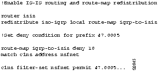
Consider the example shown in Figure 9-36. The route map conditions are initially set to deny redistribution for all addresses with the prefix 47.005.
Figure 9-36 : Configuration Example for Redistribution Using Route Maps
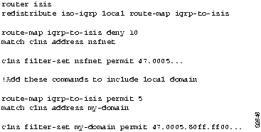
However, you realize that your own domain is 47.0005.80ff.ff00, and you have mistakenly excluded yourself from local route redistribution. In Figure 9-37, the commands with sequence number 5 ensure that the local domain will be redistributed before the larger class of 47.0005 is denied. The redistribute commands with their sequence numbers can be entered in any order, which makes it easy to modify a router configuration; you can add new permit and deny access lists at the end of the configuration file instead of having to reenter all access lists in their desired order.
Figure 9-37 : Modified Configuration Example for Redistribution Using Route Maps
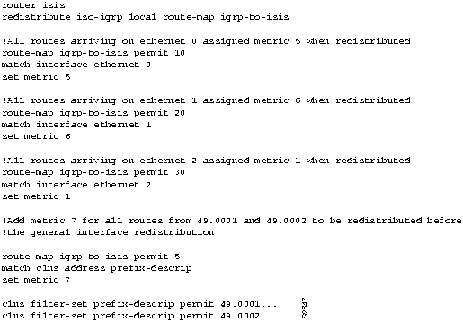
The configuration in Figure 9-38 shows how route redistribution metrics can be set so that certain addresses are treated as special cases before general rules are applied.
Figure 9-38 : Configuration Example for Setting Route Metrics
Copyright 1988-1996 © Cisco Systems Inc.


![]()
![]()
![]()
![]()
![]()
![]()
![]()
![]()