Table of Contents
Performance Problem Scenarios
Performance Problem Scenarios
This chapter presents problem-solving scenarios for identifying, isolating, and solving problems that impede throughput performance in internetworks.
These problem-solving scenarios address specific situations and illustrate the process of problem isolation and resolution. The scenarios span different protocols, media, and problem types. The objective is to illustrate a problem-solving method based on the model defined in the section "General Problem-Solving Model" in the "Troubleshooting Overview" chapter. The scenarios focus on situations in which traffic is getting to its intended destination, but network users complain about slow host response, connections dropping, or sporadic resource availability.
Each scenario includes the following components:
- Symptom statement
- Description of the internetworking environment
- Discussion of the problem isolation process
- Summary of the solution
The "Troubleshooting Internetwork Performance" chapter presents a series of symptom modules that provide snapshots of common symptoms, possible causes, and suggested actions for the protocols and technologies addressed in this publication.
For an overview of scenarios and symptom modules, see the section "Using This Publication" in the "Troubleshooting Overview" chapter.
Performance Scenario Overview
In general, performance slowdowns are considered lower-priority problems than reachability issues. However, poorly performing internetworks can degrade organizational productivity and can effectively halt operation of network applications. Performance problems manifest themselves in many ways. Slow host response, dropped connections, and high error counts all suggest that network performance is not optimal. Unfortunately, the actual sources of performance problems are often difficult to detect.
This chapter presents a series of situational discussions, including the application of various diagnostic tools. Every possible scenario cannot be covered. Indeed, the scenarios included here only scratch the surface of possible situations. However, certain common themes typically tie all connectivity problems together. This chapter illustrates the use of troubleshooting tools and techniques to identify those common themes.
The following problem-solving scenarios are presented in this chapter:
- Novell Performance Scenarios---Several performance-related scenarios illustrate typical configuration and network design problems that lead to poor performance in Novell IPX internetworks.
- Poor Performance over TCP/IP Serial Network---This scenario focuses on performance in a TCP/IP internetwork in which Cisco routers and parallel serial links join two geographically separated locations.
- Serial Link Performance Scenario---This scenario illustrates the resolution of problems associated with poor host response over a 56-kbps High-Level Data Link Control (HDLC) link.
- XNS Performance Scenarios---Several short performance-related case examples illustrate typical configuration and network design problems that can lead to poor performance in XNS internetworks.
Performance Problems in Novell IPX Internetwork after Bandwidth Upgrade
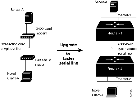
The following case illustrates a situation in which performance degrades significantly after a Novell IPX internetwork is upgraded from a 2400-baud link over a telephone line to a 9600-baud synchronous serial line.
Symptoms
Server responsiveness noticeably slows following an upgrade from a 2400-baud, direct dial-up interconnection between a client and a server to a router-based link over a 9600-baud synchronous serial line.
Environment Description
Figure 14-1 shows a map of the environment for this scenario. The following characteristics represent the relevant elements of this internetwork:
- Initial communication between Client-A and Server-A is acceptable when provided over a direct dial-up link.
- In order to share resources, Client-A is attached to an Ethernet, and the dial-up access is replaced by a 9600-baud synchronous serial line separated by two routers.
- LANs are IEEE 802.3 Ethernets.
- Novell IPX is the only protocol being routed over the point-to-point link.
Figure 14-1 : Upgrade from Dial-Up Link to 9600-Baud Connection
Diagnosing and Isolating Problem Causes
Insufficient bandwidth is the best candidate for poor server responsiveness.
In the original configuration, Server-A communicates with Client-A without any encapsulation. Although the modems attach a header to each transmission, information exchanged between ServerA and Client-A is essentially all data and varies in size depending on the kind of communication that is occurring.
In the upgraded configuration, the Ethernet segments to which Server-A and Client-A are attached require a minimum packet size of 60 bytes (which includes a 6-byte destination address, a 6-byte source address, a 2-byte type or length field, and data). The overhead associated with Ethernet encapsulation (for packets smaller than 60 bytes) can easily overwhelm the 9600-baud line, resulting in communication that is actually slower than the original direct, dial-up interconnection.
Problem Solution Summary
One solution is to disable fast switching, which uses the link-layer packet size. When fast switching is disabled, the router uses the network layer packet size. In addition, when fast switching is disabled, more buffers are available for handling peak loads.
However, with such a narrow serial pipe, the best solution is to add bandwidth. The amount of additional bandwidth required will vary depending on the situation. Certainly, if multiple clients are trying to access multiple servers, converting the 9600-baud line to a 56-kbps line would be reasonable.
Performance Problems in Novell IPX Internetwork after Switching to Routing
The following scenario illustrates a situation in which performance degrades significantly after a bridged Novell IPX internetwork is converted to routing.
Symptoms
Server responsiveness slows by an approximate factor of four after Novell IPX routing is implemented in place of bridging.
Environment Description
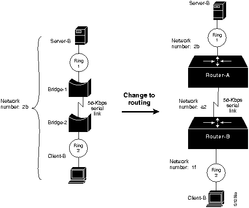
Figure 14-2 shows a map of the internetwork before and after the conversion.
Figure 14-2 : Novell IPX Interconnection Converted from Bridging to Routing
The following characteristics represent the relevant elements of this internetwork:
- Previously, communication between Client-B and Server-B was provided via two remote bridges over a 56-kbps link.
- In order to ensure a more manageable interconnection, Bridge-1 and Bridge-2 are replaced with routers (Router-1 and Router-2) over the same 56-kbps link.
- LANs are IEEE 802.5 Token Rings.
- Novell IPX is the only protocol being routed over the point-to-point link.
Diagnosing and Isolating Problem Causes
The maximum packet size limitation associated with standard NetWare in a routed environment is the best candidate for poor server responsiveness.
In a bridged environment, Server-B allows transmission of the maximum packet size associated with the media in the internetwork (1130 bytes for Ethernet, and 4202 bytes for 4-Mbps Token Ring and 16-Mbps Token Ring).
However, in a router-based internetwork, standard NetWare 3.11 and earlier Novell servers only allow for a maximum packet size of 576 bytes, regardless of media. Packet routing defaults to this smallest common size whenever multiple network numbers are detected. In addition, prior to Software Release 8.3(3), Cisco routers did not support the Novell Large Internet Packet Exchange (LIPX) NetWare-loadable module (PBURST.NLM) for Token Ring. (This module was previously known as BIGPACK.) Novell 3.12 and 4.x servers automatically find the largest packet size.
Problem Solution Summary
Two actions can help improve performance between Server-B and Client-B in this router-based internetwork:
- Implement the Novell PBURST.NLM NetWare-loadable module on the server to accommodate the transmission of packets of any size requested by clients, or upgrade Novell servers to 3.12 or 4.x.

Caution Be sure that all media and transport protocols are accounted for when implementing PBURST.NLM. If any segment does not support the larger packets, connectivity can be disrupted throughout the internetwork.
- Implement BNETX.COM at clients to support burst mode. This software implements a windowing capability that allows for larger individual units of data transfer. Alternatively, you can upgrade to NetWare 3.12 or 4.x.
Slow Novell IPX Performance over Router Connecting 16-Mbps Rings
The following scenario illustrates a situation in which performance over a router interconnecting two 16-Mbps Token Rings is slower than a comparable interconnection of two Ethernet segments.
Symptoms
Server responsiveness is slow over a router that separates two 16-Mbps rings.
Environment Description
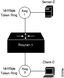
Figure 14-3 shows a map of the environment for this scenario. The following characteristics represent the relevant elements of this internetwork:
- Router-1 separates two Token Ring segments.
- Client-C (on Ring 2) accesses services on Server-C (on Ring 1).
- LANs are 16-Mbps Token Rings.
- Novell IPX is the only protocol being routed.
Figure 14-3 : Novell IPX Interconnection over Router Joining 16-Mbps Rings
Diagnosing and Isolating Problem Causes
A likely candidate for poor server response is that PBURST.NLM is not implemented on the server. PBURST.NLM allows the server to transmit packets of any size.
Problem Solution Summary
Implement the PBURST.NLM NetWare-loadable module on the server.
 Caution Be sure that all media and transport protocols are accounted for when implementing PBURST.NLM. If any segment does not support the larger packets, connectivity can be disrupted throughout the internetwork.
Implement BNETX.COM at clients to support burst mode. This software implements a windowing capability that allows the transfer of larger individual units of data.
Slow Novell IPX Performance over Ethernet Backbone
The following scenario illustrates a situation in which performance is extremely slow over an Ethernet backbone that separates two routers.
Symptoms
Slow server response among multiple Ethernet segments separated by two routers and an Ethernet backbone.
Environment Description
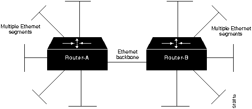
Figure 14-4 shows a map of the environment for this scenario. The following characteristics represent the relevant elements of this internetwork:
- Router-A and Router-B interconnect multiple Ethernets over an Ethernet backbone.
- LANs are IEEE 802.3 Ethernets.
- Novell IPX is the only protocol being routed.
Figure 14-4 : Novell IPX Routers Joining Multiple Ethernets over an Ethernet Backbone
Diagnosing and Isolating Problem Causes
Congestion is the best candidate for poor performance over the backbone.
You can use the following procedure to determine whether there is a congestion problem over the backbone:
Step 1 Examine the output of the show interfaces EXEC command for relative load, high and increasing levels of input errors, and drops.
Step 2 Attach a network analyzer to the backbone. Look for high levels of collisions and for bandwidth utilization in excess of 30 percent.
For information about general troubleshooting of performance problems in a routed internetwork, refer to the section "Slow Host Response over a 56-kbps HDLC Link," later in this chapter. For more information about diagnosing congestion problems, refer to the "Troubleshooting Serial Line Problems" and the "Troubleshooting Internetwork Performance" chapters.
If you determine that congestion over the Ethernet backbone is high, the only real option is to increase bandwidth. You can do this by adding additional Ethernet segments or by replacing the Ethernet backbone with a faster media, such as Fiber Distributed Data Interface (FDDI).
Problem Solution Summary
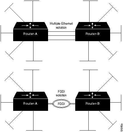
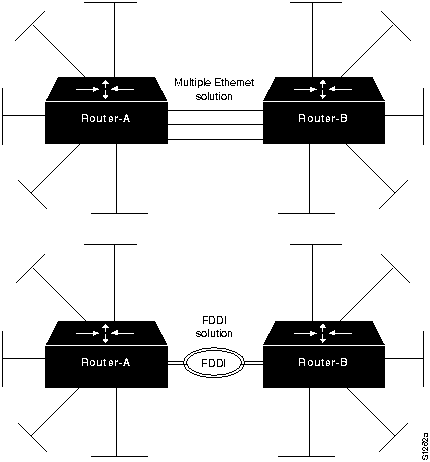
This scenario focused on improving performance over a backbone that segments multiple Ethernets by increasing bandwidth using one of two options:
- Replacing the single Ethernet backbone with multiple Ethernet segments.
- Replacing the single Ethernet backbone with an FDDI backbone.
Figure 14-5 illustrates these options.
Note If you adopt a multiple Ethernet option, remember to implement the ipx maximum-paths global configuration command. For more information about this requirement, refer to the section "Slow Novell IPX Performance over Equal Parallel Links" later in this chapter. Also note that each segment must have its own network address. For more information about duplicate network number problems, refer to the "Troubleshooting Novell IPX Connectivity" chapter.
Figure 14-5 : Alternative Solutions to Ethernet Backbone Bottleneck
Slow Novell IPX Performance over Equal Parallel Links
The following scenario illustrates a situation in which performance is less than optimal over parallel T1 links that join two routers.
Symptoms
One line appears to be heavily loaded, while the other line is either idling or indicates very low load. Users complain of slow response and intermittent connection drops.
Environment Description
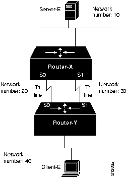
Figure 14-6 shows a map of the environment for this scenario. The following characteristics represent the relevant elements of this internetwork:
- Router-X and Router-Y interconnect two sites over parallel T1 lines running at 1.544 Mbps.
- Client-E needs to access Server-E on the other side of the serial interconnections.
- LANs are IEEE 802.3 Ethernets.
- Novell IPX is the only protocol being routed.
Figure 14-6 : Routers Joining Novell IPX Networks over Parallel T1 Lines
Diagnosing and Isolating Problem Causes
The router probably is keeping only one routing table entry per target network. This is likely to cause poor performance over the parallel serial lines. In the worst case, traffic is routed through only one line, while the second line is idle.
You can use the following procedure to determine whether traffic is being unevenly distributed between the parallel lines:
Step 1 Use the show interfaces EXEC command to examine the load for each interface. Also examine the number of input and output drops and the 5-minute output and input packet counts. Record the observed values.
Step 2 Use the clear counters privileged EXEC command and continue to monitor changes in the counters over time with the show interfaces EXEC command.
Step 3 Look for values that are substantially uneven. (For example, interface serial 0 indicates 300,000 packets total input, while interface serial 1 indicates only 1000.)
Step 4 If you determine that traffic is unevenly distributed over the serial links, use the ipx maximum-paths global configuration command to set the number of multiple paths for the router to use when transmitting traffic to any particular destination. Instead of keeping only one routing table entry, the router will use up to the specified number of paths when it determines how to route traffic. In essence, the ipx maximum-paths global configuration command forces load balancing over two lines when the number of paths is specified as 2.
Note This problem is the same for any parallel media. The suggested solution would be the same for parallel FDDI, Ethernet, or Token Ring links, as well as for parallel serial interconnections.
Problem Solution Summary
This scenario focused on improving performance over parallel links. The recommended solution is to implement the ipx maximum-paths global configuration command with the number of paths specified as 2.
Slow Novell IPX Performance over Unequal Parallel Links
The following scenario illustrates a situation in which performance is slow over parallel links of differing speeds that join two routers.
Symptoms
One line appears to be heavily loaded, while the other is either idling or indicates very low load. Users complain of slow response and intermittent connection drops.
Environment Description
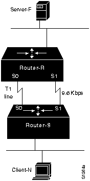
Figure 14-7 shows a map of the environment for this scenario. The following characteristics represent the relevant elements of this internetwork:
- Router-R and Router-S interconnect two sites over parallel lines. One line runs at T1 speed (1.544 Mbps) and the other line runs at 9.6 kbps.
- The ipx maximum-paths global configuration command is enabled on both routers.
- Client-N needs to access Server-F on the other side of the serial interconnections.
- LANs are IEEE 802.3 Ethernets.
- Novell IPX is the only protocol being routed.
Figure 14-7 : Routers Joining Novell IPX Networks over Unequal Parallel Lines
Diagnosing and Isolating Problem Causes
Because the Novell Routing Information Protocol (RIP) does not take line speed into consideration, load cannot be balanced effectively between these two links. For this reason, it is probable that traffic is only being routed through one line, while the second line is idle. And, because RIP does not consider line speed, the 9.6-kbps line could be completely overwhelmed, while the T1 line is relatively unused. A load-balancing problem is probably causing poor performance over the parallel serial lines.
You can use the following procedure to determine whether traffic is being unevenly distributed between the unequal parallel lines:
Step 1 Use the show interfaces EXEC command and examine the load for each interface. Also examine the number of input and output drops and the 5-minute output and input error counts. Record the observed values.
Step 2 Use the clear counters privileged EXEC command and continue to monitor changes in the counters over time with the show interfaces EXEC command.
Step 3 Look for values that are substantially uneven. (For example, interface serial 0 indicates 0 output drops, while interface serial 1 indicates 300 output drops.)
Step 4 If you determine that traffic is being unevenly distributed over the serial links, and the ipx maximum-paths global configuration command is already implemented, one solution is to make the speed on both lines match. Another solution is to use the ipx delay interface configuration command to set the tick value of the slow-speed line to a high value, which causes the slow-speed line to be used only as a backup.
Note This problem is the same for any unequal parallel media. The suggested solution would be the same for unevenly matched FDDI, Ethernet, or Token Ring links, as well as for uneven parallel serial interconnections.
Problem Solution Summary
This scenario focused on improving performance over uneven parallel links. The recommended solution is to force the speed of the parallel links to match or to use the ipx delay interface command to cause the slow-speed line to be used only as a backup.
Poor Performance over TCP/IP Serial Network
This scenario focuses on performance in a TCP/IP internetwork that uses Cisco routers and parallel serial links to join two geographically separated locations.
Symptoms
Users at Remote-Lab complain of poor host response and slow performance when connecting to hosts at the Main-Campus. In addition, during certain times of the day, large files are being transferred over the serial network. At these times, traffic becomes especially slow, but does not stop. Figure 14-8 illustrates this network topology.
Environment Description
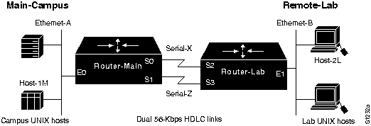
Figure 14-8 shows a map of the environment for this scenario. The following characteristics represent the relevant elements of this internetwork:
- A remote research lab (Remote-Lab) is linked to a campus network (Main-Campus) over two parallel 56-kbps HDLC lines (Serial-X and Serial-Z).
- Two routers (Router-Main and Router-Lab) join the two sites. The routers are attached to channel service units (CSUs) or data service units (DSUs) with V.35 cables.
- LANs are IEEE 802.3 Ethernets.
- UNIX workstations are used at the Remote-Lab; traffic to the Main-Campus consists of File Transfer Protocol (FTP), Telnet, and mail.
- Transmission Control Protocol (TCP/IP) is being routed over the point-to-point links.
Figure 14-8 : Dual 56-kbps Serial Link TCP/IP Internetwork Scenario Map
Diagnosing and Isolating Problem Causes
Given the situation, the following problems are the most likely candidates for poor performance between Main-Campus and Remote-Lab:
- Bad Ethernet or serial line
- Congestion
The following procedure illustrates the process of investigating potential hardware problems:
Step 1 Use the show interfaces serial EXEC command to determine the condition of the serial lines. Figure 14-9 shows output that indicates that the interfaces are minimally operational and the router can communicate with them.
Figure 14-9 : show interfaces serial Command Output
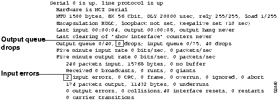
- Look for input errors and high numbers of output drops, which suggest that the serial line is being overutilized.
Step 2 Assume that the serial line is basically functional. That is, the router reports that the interface and line protocol are up. Now, use an extended ping test to isolate the point where traffic is being slowed. Look for drops, failures, and timeouts. Figure 14-10 illustrates an example of an extended ping test that detects failures.
Figure 14-10 : ping Command Output
-
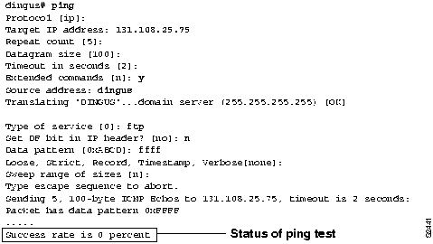
Step 3 Starting with the router closest to the remote hosts, ping various nodes in the path, looking for the point at which drops start to occur. For instance, ping from Router-Lab to Host-2L. If pings are successful, you can eliminate Ethernet-B as the source of congestion problems. Next, ping from Router-Main to Host-1M. If pings are successful, you can eliminate Ethernet-A as the source of congestion problems.
Step 4 If these tests indicate no problems, ping between the routers. First, ping from Router-Main to the IP address associated with interface Ethernet1 on Router-Lab. Next, ping each of the serial interfaces on Router-Lab. If you find any ping failure on the serial lines, refer to serial debugging as discussed in the "Troubleshooting Serial Line Problems" chapter and to the additional information provided in the "Troubleshooting Router Startup Problems" chapter.
Step 5 If you determine that the problem is indeed one of congestion because of bandwidth overutilization, you must decide whether it is more effective to add bandwidth (in the form of another serial circuit) or to adjust the router configuration.
Step 6 If you see load values of about 50 percent and high numbers of input errors and output drops, consider implementing priority queuing to force Telnet to be given higher precedence over other packet types. Priority queuing helps ensure reasonable connection service to users, even during periods when file transfers are taking place. Figure 14-11 illustrates a configuration for Router-Lab that establishes priority queuing and assigns
port 23 (Telnet) a higher priority than other TCP/IP protocols, such as mail (port 25).
Figure 14-11 : Configuration Showing Priority Queuing Specification
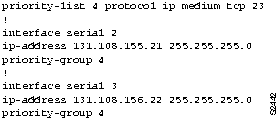
Note One reason why Telnet traffic can be bumped from the buffer queues is the tendency of larger FTP packet types to collect in buffers. When FTP traffic is high, the smaller Telnet packets are squeezed out of the output queues, resulting in retransmissions, session timeouts, and generally slower connection performance. Priority queuing can relieve marginal cases of this kind.
Step 7 If you see a consistent load of close to 90 percent, as well as input errors and output drops, priority queuing is not likely to help. With consistently high congestion, the best solution is additional or faster serial links.
Problem Solution Summary
This scenario focused on the following performance problems in TCP/IP internetworks:
- Isolating problem nodes and eliminating potential problems using extended ping tests
- Determining when to enable priority queuing and when to add bandwidth
- Specifying priority queuing to force the router to give a specific TCP/IP socket a higher priority than other protocols
Slow Host Response over a 56-kbps HDLC Link
When designing and implementing internetworks, it is important to factor in any potential changes and expectations of growth. This is especially important when certain network elements are at risk of becoming bottlenecks---such as point-to-point serial links. Bandwidth that appears to be sufficient today may be inadequate in a year. And the budget may not exist to add another drop or replace the existing service. This scenario explores a situation in which a router can be used to improve performance over a serial link that does not meet user requirements.
Symptoms
Users at a remote site complain of consistently degraded performance when they connect to hosts at the home office. Performance previously was acceptable, but now slows substantially during peak use periods.
Environment Description
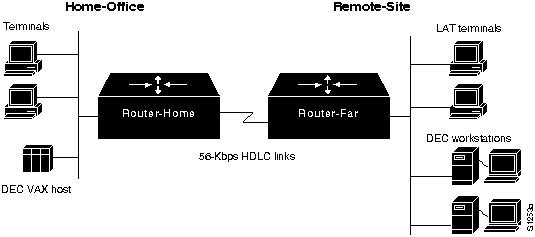
Figure 14-12 shows a map of the environment for this scenario. The following characteristics represent the relevant elements of this internetwork:
- A single remote sales office (Remote-Site) is linked to the corporate network (Home-Office) over a 56-kbps HDLC line.
- Two routers (Router-Home and Router-Far) join the two sites over a 56-kbps link. The local router attachment is to a CSU/DSU using a V.35 cable.
- LANs implemented are IEEE 802.3 Ethernets.
- DEC workstations and various ASCII terminals are used at the Remote-Site. Traffic to the HomeOffice consists of file transfers, virtual terminal connections, and electronic mail.
- Native DECnet is routed over the point-to-point link, while DEC local-area transport (LAT) protocol is the sole protocol being bridged.
- In this situation, the observed level of traffic is very high on the serial link. Spikes of 80 to 90 percent of bandwidth are commonly detected.
Figure 14-12 : Scenario Map for a 56-kbps Point-to-Point Performance Problem
Diagnosing and Isolating Problem Causes
Given the situation, the following problems are the best candidates for poor performance:
- Bad serial line
- Overutilized serial line
- Interface card out of buffers
- Misconfigured hosts
The following procedure illustrates the process of investigating potential hardware problems:
Step 1 Use the show interfaces serial EXEC command to determine the condition of the serial line. Figure 14-13 shows output indicating that the interfaces are minimally operational and the that router can communicate with them.
Figure 14-13 : show interfaces serial Command Output
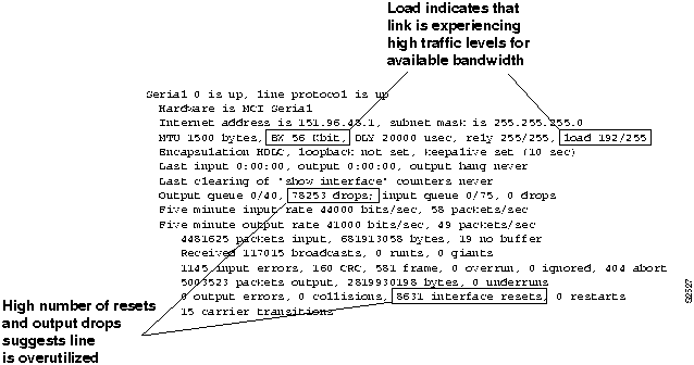
- Of interest in this display is the fact that the value for input errors is relatively low, but the values for interface resets and output drops are both high. Another clue is that the load field indicates that the link is experiencing a load of about 75 percent of available bandwidth (the value is shown as a "percentage" of 255, such that a link seeing one third utilization (33/100) would have a load value of 85/255). This information combines to suggest that the serial line is functional but is being overutilized.
Note The value displayed in the load field is based on a 5-minute weighted average of traffic activity on the interface. This means that all traffic values for the last 5 minutes are taken into account, but the more recent values are weighted more heavily. Large fluctuations in this number over time usually indicate that the interface is experiencing periodic congestion, which is common on low-speed interfaces.
Note that the value shown in the load field is based on the figure shown in the BW (bandwidth) field on the same line. The BW field normally displays a default value (typically 56 or 1544 kbps) that correlates to the type of interface. If you know that the amount of bandwidth actually available differs from the default value, and you want the load to be calculated more accurately, use the bandwidth interface configuration command to change the BW value.
To monitor changes in the number of dropped packets, follow these steps:
Step 1 Obtain the show interfaces serial EXEC command output. (See Figure 14-13.)
Step 2 Write down the number of output drops. (See Figure 14-13.)
Step 3 Use the clear counters privileged EXEC command to reset counters on the target interface.
Step 4 Check the change to the output drops field in an hour; if the value is around 1000 or more, the link is probably overutilized.
Note The DECnet protocol is particularly sensitive to drops. If your internetwork involves handling of DECnet traffic, you must ensure that drops are eliminated.
- To further confirm that the serial link is overutilized, use the show buffers EXEC command. Figure 14-14 illustrates the output from this command. In this example, there are a large number of failures and misses, which suggests a problem with the system-level buffers, and that the router is trying to transmit traffic that exceeds the interface bandwidth.
Note An interface reset on one end of a serial link causes aborts on the other end; these appear as input errors (as well as aborts). This is why it is essential to inspect both ends of the serial link (using the show interfaces EXEC command).
Figure 14-14 : show buffers Command Output
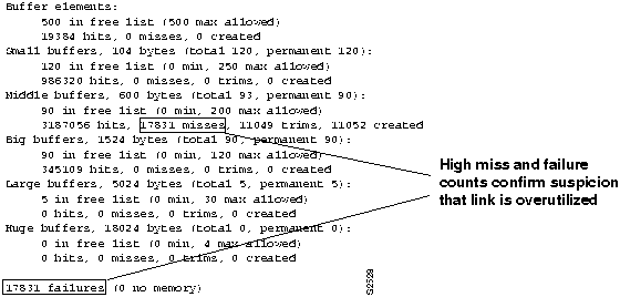
Step 5 Next, look at the router configuration files for clues. If fast switching is not explicitly disabled for all protocols, disable fast switching, which is enabled by default. For DECnet, use the no decnet route-cache interface configuration command to disable fast switching. This change forces the router to use system-level memory buffers (instead of board-level buffers), which, under certain conditions, can improve overall throughput.
Step 6 Although disabling fast switching can improve performance over the serial link, assume that problems still persist during peak demand times. The next step is to prioritize traffic using the priority queuing function. By assigning a high priority to bridged (LAT) packets, the LAT traffic takes precedence over any other traffic. Again, this enhances performance, but might not entirely eliminate peak period sluggishness.
Step 7 Tune system buffers. By setting a minimum number of system buffers as available at all times, you can significantly reduce the bottleneck at the serial link.
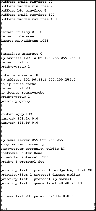
- Figure 14-15 illustrates a complete configuration listing for Router-Home (obtained using the write terminal privileged EXEC command) that includes the changes suggested in Steps 2 through 4.
Note When customizing buffer settings, you must carefully match the buffer specifications with the hold-queue limits. For more information about managing buffers and specifying hold-queue limits, refer to the "Troubleshooting Serial Line Problems" chapter.
Figure 14-15 : Complete Configuration Showing Changes Needed to Improve Performance over a 56-kbps Line
Problem Solution Summary
This scenario revolved around an interface that was overworked. The immediate reaction to this situation might be to add another link in parallel. Ultimately, adding bandwidth is probably required. But that might not be an immediately available option. Perhaps the protocol being used cannot handle load balancing, or you simply cannot afford the added expense of another physical link in your current budget.
The actions offered in this example explore options that use the existing physical configuration, but reconfigure the way traffic is handled. The following modifications can help optimize traffic over an overloaded 56-kbps link:
- Disabling fast switching.
- Enabling priority queuing for bridged (LAT) traffic. Note that the configuration in Figure 14-15 includes an access list that permits bridging of LAT packets, but blocks bridging of any other packets.
- The configuration also shows specific queue depths for high, medium, normal, and low priority packets. If you implement priority queuing, try these as a starting point. Your actual implementation will take some tuning. With LAT, reducing the number of drops will improve performance; however, avoid assigning arbitrarily large queue limits, because there can be performance side effects. Excessively large queues can cause timing problems when packets are buffered for too long a time.
- As you tune the queue-limit values assigned in the priority-list global configuration command, check the interface activity with the show interfaces EXEC command to monitor the number of drops. A typical queue-limit value for the high-priority packets is 50.
- This solution is particularly applicable to situations involving routing of DECnet traffic and bridging of LAT traffic. Set DECnet queues to 100 to help prevent drops if necessary.
Note If an interface is dropping packets at a traffic load near or approaching100 percent (255/255 load), you must add bandwidth in the form of another line or a higher-capacity line.
Slow XNS Performance over Ethernet Backbone
This scenario illustrates a situation in which performance is extremely slow over an Ethernet backbone that separates two routers.
Symptoms
Slow server response among multiple Ethernet segments separated by two routers and an Ethernet backbone.
Environment Description
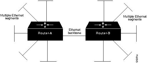
Figure 14-16 shows a map of the environment for this scenario. The following characteristics represent the relevant elements of this internetwork:
- Router-A and Router-B interconnect multiple Ethernets over an Ethernet backbone.
- LANs are IEEE 802.3 Ethernets.
- XNS is the only protocol being routed.
Figure 14-16 : XNS Routers Joining Ethernets over Ethernet Backbone
Diagnosing and Isolating Problem Causes
Congestion is the best candidate for poor performance over the backbone. You can use the following two methods to determine whether the backbone has a congestion problem:
- Issue the show interfaces EXEC command and examine the output for relative load, increasingly high levels of input errors, and drops.
- Attach a network analyzer to the backbone and look for high levels of collisions, and bandwidth utilization in excess of 30 percent.
For information about general troubleshooting of performance problems in a routed internetwork, refer to the section "Slow Host Response over a 56-kbps HDLC Link," earlier in this chapter. For more information about diagnosing congestion problems, refer to the "Troubleshooting WAN Connectivity" and the "Troubleshooting Internetwork Performance" chapters.
If you do determine that congestion over the Ethernet backbone is high, the only option is to increase bandwidth. You can do this by either adding additional Ethernet segments or by replacing the Ethernet backbone with a faster media, such as FDDI.
Problem Solution Summary
This scenario focused on improving performance over a backbone segmenting multiple Ethernets by increasing bandwidth using one of two options:
- Replacing the single Ethernet backbone with multiple Ethernet segments
- Replacing the single Ethernet backbone with an FDDI backbone
Figure 14-17 illustrates these options.
Note If you adopt a multiple Ethernet option, remember to implement the xns maximum-paths global configuration command. For more information about this requirement, refer to the beginning of the section "Slow XNS Performance over Equal Parallel Links," earlier in this chapter. Also note that each segment must have its own network address. For more information about duplicate network number problems, refer to the "Troubleshooting XNS Connectivity" chapter.
Figure 14-17 : Alternative Solutions to Ethernet Backbone Bottleneck in XNS Network
Slow XNS Performance over Equal Parallel Links
This scenario illustrates a situation in which performance is less than optimal over parallel T1 links joining two routers.
Symptoms
One line appears to be heavily loaded, while the other is either idling or indicates very low load. Users complain of slow response and intermittent connection drops.
Environment Description
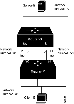
Figure 14-18 shows a map of the environment for this scenario. The following characteristics represent the relevant elements of this internetwork:
- Router-X and Router-Y interconnect two sites over parallel T1 lines running at 1.544 Mbps.
- Client-E needs to access Server-E on the other side of the serial interconnections.
- LANs are IEEE 802.3 Ethernets.
- XNS is the only protocol being routed.
Figure 14-18 : Router Joining XNS Networks over Parallel T1 Lines
Diagnosing and Isolating Problem Causes
A likely cause for poor performance over parallel serial lines is that the router is keeping only one routing table entry per target network. In the worst case, traffic is only routed through one line, while the second line is idle.
Use the following procedure to determine whether traffic is being unevenly distributed between the parallel lines:
Step 1 Issue the show interfaces EXEC command and examine the load for each interface. Also examine the number of input and output drops and the 5-minute output and input packet counts. Record the observed values.
Step 2 Use the clear counters privileged EXEC command and continue to monitor changes in the counters over time with the show interfaces EXEC command.
Step 3 Look for values that are substantially uneven. (For example, interface serial 0 indicates 500 packets total input, while interface serial 1 indicates 10.)
Step 4 If you determine that traffic is unevenly distributed over the serial links, use the xns maximum-paths global configuration command to set the number of multiple paths for the routers to use when transmitting traffic to any particular destination. Instead of keeping only one routing table entry, each router will use up to the specified number of paths when it determines how to route traffic. In essence, the xns maximum-paths global configuration command forces load balancing over two lines when the number of paths is specified as 2.
Note This problem is the same for any parallel media. Therefore, the suggested solution would be the same for parallel FDDI, Ethernet, or Token Ring links, as well as for parallel serial interconnections.
Problem Solution Summary
This scenario focused on improving performance over parallel links. The recommended solution is to implement the xns maximum-paths global configuration command on the routers with the number of paths specified as 2.
Slow XNS Performance over Unequal Parallel Links
This scenario illustrates a situation in which performance is slow over parallel links of differing speeds that join two routers.
Symptoms
One line appears to be heavily loaded, while the other is either idling or indicates very low load. Users complain of slow response and intermittent connection drops.
Environment Description
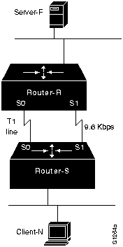
Figure 14-19 shows a map of the environment for this scenario. The following characteristics represent the relevant elements of this internetwork:
- Router-R and Router-S interconnect two sites over parallel lines with one line running at T1 speed (1.544 Mbps) and the other line running at 9.6 kbps.
- xns maximum-paths global configuration command is enabled on both routers.
- Client-N needs to access Server-F on the other side of the serial interconnections.
- LANs are IEEE 802.3 Ethernets.
- XNS is the only protocol being routed.
Figure 14-19 : Router Joining XNS Networks over Unequal Parallel Lines
Diagnosing and Isolating Problem Causes
Because the XNS RIP routing protocol does not take line speed into consideration, the load cannot be balanced effectively between the two links. Lack of load balancing is probably causing poor performance over the parallel serial lines. It is quite possible that traffic is only being routed through one line, while the second line is idle. Because RIP does not consider line speed, the 9.6-kbps line could be completely overwhelmed, while the T1 line is relatively unused.
You can use the following procedure to determine whether traffic is being unevenly distributed between the parallel lines:
Step 1 Issue the show interfaces EXEC command and examine the displayed load for each interface. Also examine the number of input and output drops and the 5-minute output and input packet counts. Record the observed values.
Step 2 Use the clear counters privileged EXEC command and continue to monitor changes in the counters over time with the show interfaces EXEC command.
Step 3 Look for values that are substantially uneven. (For example, interface serial 0 indicates 10 packets total input, while interface serial 1 indicates 500.)
Step 4 If you determine that traffic is being unevenly distributed over the serial links, and the xns maximum-paths paths global configuration command is already implemented, you can make the speed on both lines match, or you can eliminate the slow-speed line altogether.
Note This problem is the same for any differing parallel media. Therefore, the suggested solution would be the same for unevenly matched FDDI, Ethernet, or Token Ring links, as well as for uneven parallel serial interconnections.
Problem Solution Summary
This scenario focused on improving performance over uneven parallel links. The recommended solution is to force the speed of the parallel links to match or to eliminate the slow-speed link.
Copyright 1988-1996 © Cisco Systems Inc.


![]()

![]()


![]()
![]()
![]()
![]()
![]()
![]()
![]()
![]()