|
|
Troubleshooting XNS Connectivity
This chapter presents protocol-related troubleshooting information for Xerox Network Systems (XNS) connectivity problems and consists of the following sections:
The symptom modules consist of the following sections:
XNS Network Server Connectivity Scenario
With the emergence of XNS as an important PC-based network operating environment, network administrators have had increasing requirements to interconnect and segment PC LANs running the XNS networking protocol. This scenario focuses on a variety of problems that can impair server access over a routed internetwork.
Figure 13-1 is a map of the XNS internetwork discussed in this case. It illustrates an interconnection between two sites over an arbitrary serial network. The symptom encountered in this scenario is that Client-A cannot access Server-1 and Server-2 on the other side of the serial link. However, ClientA can access Server-3 on the local wire.
Because no connections can be made over the serial link, it initially appears that there is a problem with traffic getting through the routers.
Figure 13-1 : Initial XNS Connectivity Scenario Map
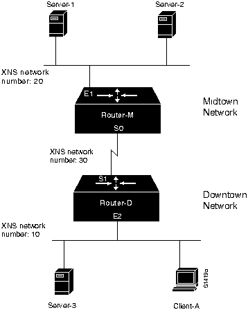
The relevant elements of the internetworking environment shown in Figure 13-1 can be summarized as follows:
Diagnosing and Isolating Problem Causes
Given the situation, several problems could explain connectivity symptoms.
The following problems are likely candidates for the first symptom. (Client-A cannot access services on Server-1 and Server-2.)
This list is loosely ordered according to a combination of two criteria: ease of problem determination and likelihood of being the actual problem.
In general, it is useful to eliminate the most likely problems first and then to tackle the more complex problems as necessary. The problem-solving process that follows illustrates this strategy.
After you determine a possible problem list, you must analyze each potential cause. The following discussion considers the problems listed and illustrates the resolution of discovered problems.
Checking Physical Attachment of Clients to Network
The first step is to determine whether clients are physically attached to the network, as follows:
In this case, assume that connectivity is verified up to Router-D from Client-A.
Checking Physical Attachment of Servers to Network
The next step is to determine whether the remote servers are attached to their Ethernet segments. This process is very similar to determining whether the clients are attached to the Downtown segment.
In this case, assume that connectivity is verified up to Router-M from Server-1.
Use the write terminal privileged EXEC command to determine whether XNS routing is enabled. Use the xns routing global configuration command if it is not. Use the show protocols EXEC command to determine what protocols are running on which interfaces.
Use the write terminal privileged EXEC command to determine whether the network number matches the client or the server network number. Use the xns network interface configuration command to change or assign the proper network number to the interface.
Checking Router Interface Status
In the process of eliminating the preceding problems, it is highly likely that the status of each router interface has been verified. You can further confirm the status of the router interfaces using the following procedure:
Again, for the purposes of this scenario, assume that all of the interfaces are functional.
Checking for Access List Problems
Access list problems are commonly the cause of connectivity problems. For details concerning access list issues, refer to Table 13-1 in the "Clients Cannot Communicate with XNS Servers over Routers" symptom module later in this chapter.
For the purposes of this scenario, assume that the write terminal privileged EXEC command output for both Router-D and RouterM indicates that there are no relevant access list specifications.
Checking for Nonunique MAC Addresses on Routers
MAC addresses for XNS configurations are obtained in one of two ways: either from the router hardware address embedded in the system firmware or by random assignment (when the system software initializes before the interface is initialized). In some rare cases, the randomly generated MAC address for different routers will be the same. If these numbers are not unique, and the routers are on the same internetwork, communication will not occur. If Router-M and Router-D have the same MAC address, no traffic will traverse the serial link.
Use the following procedure to check for nonunique MAC addresses:
In general, this problem occurs more frequently in Token Ring implementations. For the purposes of this scenario, assume that the MAC addresses are different.
Checking for Misconfigured xns forward-protocol Command
Next, look for a missing or misconfigured xns forward-protocol global configuration command, as follows:
Assume for the purposes of this scenario that the xns forward-protocol command is properly configured. Unfortunately, connectivity to the remote hosts from Client-A is still blocked when test connections are attempted.
Checking for Misconfigured Helper Addresses
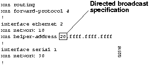
Next, look for a missing or misconfigured XNS helper address specification. On each of the routers, issue the write terminal EXEC command to look for xns helper-address interface configuration command specifications. The xns helper-address command must include either an all nets specification (-1.ffff.ffff.ffff) or directed broadcast specification (20.ffff.ffff.ffff).
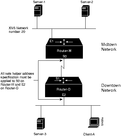
If the all nets specification is used, it must be specified on Router-M (serial interface S0) and Router-D (Ethernet interface E2). Figure 13-2 illustrates the flow of broadcast traffic from clients and the application of the all nets broadcast specification. If a directed broadcast specification is used, it is only required on Router-D (Ethernet interface E2).
Figure 13-2 : All Nets Helper Address Specification Illustration Assume that the helper address is not included in the original configuration and is added as a correction. This restores connectivity between Client-A and the remote hosts.
This scenario focused on diagnosing blocked connectivity in XNS internetworks. The problem that was discovered was that the helper address specification was not present in the configuration. This was resolved with the addition of a directed-broadcast helper address which allowed the routers to forward XNS broadcast packets.
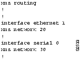
Figure 13-3 and Figure 13-4 provide representative configuration listings for Router-M and RouterD as discussed in this scenario. These configurations illustrate the configuration commands required to interconnect the two Ethernet segments over the T1 line.
Figure 13-3 : Relevant XNS Configuration Commands for Router-D Figure 13-4 : Relevant XNS Configuration Commands for Router-M XNS Internetworking Connectivity Symptoms
The symptom modules in this section pertain to XNS internetwork problems. Specific XNS connectivity symptoms are discussed in the following sections:
Clients Cannot Communicate with XNS Servers over Routers
Symptom: Clients might not be able to connect to servers on their directly connected networks. In either case, no connections can be made to servers on the other side of the router. Table 13-1 outlines possible causes and suggested actions when clients cannot communicate with XNS servers over routers.
Table 13-1 : XNS: Clients Cannot Communicate with XNS Servers over Router
XNS Broadcast Packets Cannot Get through Router
Symptom: Clients are unable to get response from servers using XNS broadcast when they attempt to connect over a router. Table 13-2 outlines possible causes and suggested actions when XNS broadcast packets cannot get through a router.
Table 13-2 : XNS: XNS Broadcast Packets Cannot Get through Router
Helper Address Specification Hints
The following illustrations and accompanying text discuss some of the implications of XNS helper address assignment, some potential pitfalls, and general behavioral characteristics. The Router Products Command Reference and Router Products Configuration Guide publications provide details about configuration commands associated with helper address assignment.
Basic Helper Address Assignment
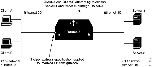
Consider the simple configuration illustrated in Figure 13-5. In this case, Router-A separates two Ethernet segments (Ethernet-20 and Ethernet-10). Clients on Ethernet-20 must be able to access services from Server-1 and Server-2 on Ethernet-10.
Figure 13-5 : Basic Helper Address Network The helper address specification is as follows:
As an alternative, you can specify a network number. In this case, specify XNS network 10 as follows:
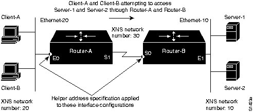
The network configuration illustrated in Figure 13-6 is similar to that illustrated in Figure 13-5, except that Ethernet-20 and Ethernet-10 are separated by a serial network and two routers (Router-A and Router-B). As before, clients on Ethernet-20 must be able to access services from Server-1 and Server-2 on Ethernet-10.
Figure 13-6 : Single Serial Interconnection Helper Address Network Assuming the use of the all nets broadcast address, the helper address specifications for the two routers would be as follows:
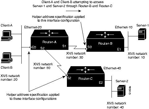
The key difference between the following example and prior examples is that Server-1 and Server2 are now on separate Ethernet segments, and clients access Server-1 and Server-2 via different routers (RouterB and Router-C). Refer to Figure 13-7.
Figure 13-7 : All Nets Multiple Serial-Line Helper Address Specification The all nets broadcast configurations for the routers follow:
Helper Behavior with Parallel Routers
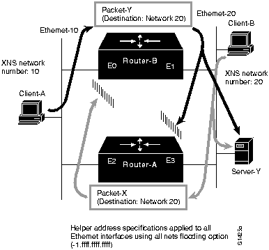
Use care in assigning broadcast-type helper addresses when XNS networks are interconnected over multiple routers and when clients are using XNS broadcast. Although traffic will not permanently loop, local client queries can leak out through a router, resulting in excess traffic. Consider the situation illustrated in Figure 13-8.
Figure 13-8 : XNS Helper Address Handling with Parallel Routers In this example, helper addresses are assigned to the Ethernet interfaces on Router-A and Router-B. The interface configurations might be as follows:
Now consider Packet-X, a client query from Client-B that is also intended for Server-Y. In this case, the broadcast packet finds its server on the same wire to which it is connected. However, Router-A forwards this broadcast because the source address is local---which puts the locally targeted packet onto XNS network 10. This packet will continue to propagate outward through the network until the internetwork terminates (or until the packet has traversed 15 routers), but it will not leak back into XNS network 20 because the routers see that the source network in the packet is 20. In no case is the packet sent back along the path to its source network. In the preceding example, the packet would be dropped when it reaches Ethernet interface E0 on Router-B.
This situation is a type of partial loop. True routing loops are prevented, but some excess traffic is created.
Clients Cannot Connect to Server over Packet-Switched Network
Symptom: Local servers are responding, but servers on the other side of a packet-switched network (PSN) that interconnects routers do not respond. A router appears to block XNS over the PSN. Table 13-3 outlines possible causes and suggested actions when clients cannot connect to a server over a PSN.
Table 13-3 : XNS: Clients Cannot Connect to Server over PSN
Notes about PSN Address Map Specifications
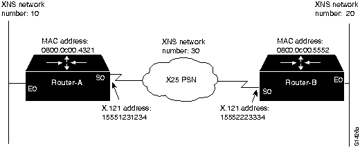
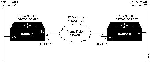
When routing XNS (or any protocol) over a PSN, you must specify mapping between the protocol and the PSN addresses. Consider the two examples illustrated in Figure 13-9 and Figure 13-10. Figure 13-9 illustrates an address map specification when routing XNS over an X.25 PSN, while Figure 13-10 illustrates an address map specification when routing XNS over a Frame Relay network. Relevant configurations and a brief explanation of command variables are provided in the following discussions. For more information about address map specifications, refer to the Router Products Configuration Guide and Router Products Command Reference publications.
Address Mapping for XNS-to-X.25 Interconnection
As illustrated in Figure 13-9, XNS-to-X.25 address map specifications would be required for both Router-A and Router-B.
Figure 13-9 : Network Diagram Illustrating XNS-to-X.25 Mapping The specific interface configurations are as follows:
Figure 13-10 illustrates essentially the same interconnection arrangement as Figure 13-9, except that the PSN used is a Frame Relay network. In an analogous manner, XNS-to-Frame Relay address map specifications would be required for both Router-A and Router-B.
Figure 13-10 : Network Diagram Illustrating XNS-to-Frame Relay Mapping The specific interface configurations would be as follows:
Copyright 1988-1996 © Cisco Systems Inc.
Possible Causes
Suggested Actions
Clients or servers are not attached to network
Router interface is not functioning
Router network number specification is misconfigured for XNS server, causing problems for RIP
Misconfigured access list
Backdoor bridge between segments
Nonfunctional Fiber Distributed Data Interface (FDDI) ring
Nonfunctional serial link
Nonfunctional Ethernet backbone
Nonfunctional Token Ring backbone
Possible Causes
Suggested Actions
Missing xns helper-address interface configuration command
Misconfigured xns helper-address specification
interface ethernet 0
xns helper-address -1.ffff.ffff.ffff
interface ethernet 1
xns helper-address 40.ffff.ffff.ffff
Missing xns forward-protocol router configuration command
Misconfigured access list
interface ethernet 0
xns network 20
xns helper-address -1.ffff.ffff.ffff
Here, -1 is used to specify flooding to all nets.
interface ethernet 0
xns network 20
xns helper-address 10.ffff.ffff.ffff
Helper Address Configuration over a Single Serial Interconnection
!Router-A helper address specification:
!
interface ethernet 0
xns network 20
xns helper-address -1.ffff.ffff.ffff
!Router-B helper address specification:
!
interface serial 0
xns network 30
xns helper-address -1.ffff.ffff.ffff
As in the prior example, -1 is used to specify flooding to all nets. Note that the helper address specification is required on Router-B because of the use of the all nets (-1) network specification (on Router-A). You can specify a specific network number as an alternative. In this case, you would specify XNS network 10 on Router-A only as follows:
!Router-A helper address specification:
!
interface ethernet 0
xns network 20
xns helper-address 10.ffff.ffff.ffff
Helper Address Configuration over Multiple Serial Interconnections
!Router-A helper address specification:
!
interface ethernet 0
xns network 20
xns helper-address -1.ffff.ffff.ffff
!Router-B helper address specification:
!
interface serial 0
xns network 30
xns helper-address -1.ffff.ffff.ffff
!Router-C helper address specification:
!
interface serial 2
xns network 50
xns helper-address -1.ffff.ffff.ffff
Note that the helper address specification is required on both Router-B and Router-C because of the use of the all nets (-1) network specification on Router-A.
!Router-B helper address specifications:
!
interface ethernet 0
xns network 10
xns helper-address -1.ffff.ffff.ffff
!
interface ethernet 1
xns network 20
xns helper-address -1.ffff.ffff.ffff
!Router-A helper address specifications:
!
interface ethernet 2
xns network 10
xns helper-address -1.ffff.ffff.ffff
!
interface ethernet 3
xns network 20
xns helper-address -1.ffff.ffff.ffff
Consider what happens to Packet-Y from Client-A that is destined for Server-Y on XNS network 20. Assume that no access lists are in place and that Router-B is the first to get a query from ClientA. Because the query is intended for an offnet host, Router-B broadcasts the query out of Ethernet interface E1 and onto XNS network 20. The broadcast finds its way to Server-Y (causing a response, assuming that Server-Y is operational) and also lands at Ethernet interface E3 on Router-A. There, the packet is dropped. This is the expected behavior.
Possible Causes
Suggested Actions
X.25 address mapping error
Frame Relay address mapping error
Misconfigured network number specification on servers or routers
Encapsulation mismatch
!Router-A
interface serial 0
x25 map xns 30.0800.0c00.5552 15552223334 broadcast
! Above specifies XNS-to-X.121 address map configuration for Router-A
!Router-B
interface serial 1
x25 map xns 30.0800.0c00.4321 15551231234 broadcast
! Above specifies XNS-to-X.121 address map configuration for Router-B
In the preceding configurations, the MAC address is obtained using the write terminal privileged EXEC command on the target router. Look for the xns routing router configuration command in the configuration listing. It is displayed with the auto-generated MAC address appended to the command. For Router-A in Figure 13-9, you would see the following listing:
xns routing 0800.0c00.4321
Address Mapping for XNS-to-Frame Relay Interconnection
!
interface serial 0
frame-relay map xns 30.0800.0c00.5552 20 broadcast
! Above specifies XNS-to-DLCI address map configuration for Router-A
interface serial 0
frame-relay map xns 30.0800.0c00.4321 30 broadcast
! Above specifies XNS-to-DLCI address map configuration for Router-B
In these example configurations, the MAC address is obtained in the same manner as described in the X.25 example: use the write terminal privileged EXEC command on the target router and look for the xns routing router configuration command in the configuration listing.
![]()
![]()
![]()
![]()
![]()
![]()
![]()
![]()