|
|

Upgrading MEC and C2MEC Type 5.1 Cards to Microcode Version 2.4 or Version 10.3
Product Numbers: MC-MEC5.1-V2.4= and MC-MEC5.1-V10.3=
This publication describes how to upgrade the Type 5.1 multiport Ethernet controller cards to Microcode Version 2.4 or Microcode Version 10.3.
Microcode Version 2.4 is compatible only with the first generation ciscoBus controller card (CSC-CCTL). Microcode Version 10.3 is compatible with, and required for use with, the second-generation ciscoBus controller card (CSC-CCTL2). If you are replacing a CSC-CCTL card with a CSC-CCTL2 card, you must upgrade the microcode on all ciscoBus interface cards to Version 10.0 or later.
Compatibility requirements for the CSC-CCTL2 are described in the section "Verifying CCTL2 Compatibility---Microcode Version 10.0 or Later Only."
In the following sections of this publication, the term MEC is used to indicate the CSC-MEC (used with first-generation ciscoBus) and CSC-C2MEC (used with second-generation ciscoBus) cards, unless otherwise indicated.
Microcode Version 2.4 and Microcode Version 10.3 are used with the Type 5.1 MEC card (Revision E or above). Earlier revisions of the card (Revisions A, C, or D, all of which are MEC card Type 5.0) are not compatible with the microcode versions described in this publication.
If you have a MEC Type 5.0 card, you must upgrade the card to a Type 5.1 card before installing either of these microcode versions. Instructions for determining the revision level of your current card are provided in the section "System Compatibility."
The upgrade procedure is the same for both microcode versions; only the component part numbers are different. References to part number tables are provided in the appropriate steps in the procedure.
Read the requirements and procedures in this section to ensure that your MEC card is compatible with the new microcode and that you have the proper tools and parts to complete this procedure without interruption.
Your current system must meet the following compatibility requirements before you install the new microcode:
The Microcode Release Note publication (Document Number 78-1069-xx---where xx is the latest version) provides the latest information on both the recommended and minimum required microcode versions for using all cards with Software Release 8.2 through Software Release 9.21. If the latest microcode version implements features that you are not using in your system and you already have the minimum required microcode version installed, there is no requirement to update the microcode.
New microcode versions occasionally fix bugs and provide performance enhancements in addition to implementing new features, and you will obtain maximum performance and reliability by upgrading to the latest recommended version.
Determine the card type (5.0 or 5.1) and microcode version (1.6 through 10.1) of all installed MEC cards with the show controller cbus command. You can also view the card type and the card revision level (A, C, D, E, or above) printed on the part number label, which is located on one of the ejector tabs and is visible when the card is installed in the card cage.
To display card type and microcode version, enter the show controller cbus command. The first line of the display for each installed MEC card (MEC 0, MEC 1, and so forth) should indicate a card Type 5.1.
The following example shows an MEC card and a first generation ciscoBus card (CSC-CCTL):
Router# show cont cbus
cBus 1, controller type 3.0, microcode version 2.0
  [text omitted]
MEC 0, controller type 5.1, microcode version 2.3
Verify that the MEC card type is 5.1, and the microcode version is 2.1 or later. If not, you must upgrade your card before proceeding. Contact a customer service representative for upgrade information.
The label showing the version is affixed to one of the ejector tabs on the front edge of the card; it is not necessary to remove the card to see the label. To view the label, you must first remove the chassis front access panel as described in steps 1 and 2 of the section "Microcode Upgrade Procedure."
The CSC-CCTL2 card is required to run ciscoBus network interface cards (with the C2 designator). The C2 indicates that a ciscoBus card is running Microcode Version 10.0 or later and is, therefore, compatible with the CSC-CCTL2 card.
For example, when the microcode on an MEC card is first changed to Version 10.0, the name of the card changes from CSC-MEC to CSC-C2MEC to indicate that it is CCTL2-compatible. If you are installing a new CSC-CCTL2, you must upgrade all ciscoBus interface cards to Microcode Version 10.0 or later. These cards and their compatibilities are listed in Table 1.
Table 1 ciscoBus Interface Card Compatibility Requirements
| CCTL Card | CCTL2 Card | Description |
|---|---|---|
| CSC-CCTL | CSC-CCTL2 | ciscoBus controller card |
| CSC-FCI | CSC-C2FCI | Fiber Distributed Data Interface (FDDI) |
| CSC-C2FCIT | FDDI with translational bridging | |
| CSC-HSCI | CSC-C2HSCI | High-Speed Serial Interface (HSSI) |
| CSC-C2CTR | ciscoBus Token Ring interface, 4/16 megabits per second (Mbps) | |
| CSC-MEC | CSC-C2MEC | Multiport Ethernet controller interface |
Display a description of the current ciscoBus card and ciscoBus interface cards with the show controller cbus command. The name and controller type of each ciscoBus card, the ciscoBus slot in which it is installed, and the microcode version of each card is displayed. (Additional statistical information is also displayed for each interface card, but is omitted from the example that follows.)
When installing Microcode Version 10.3 (or later), the ciscoBus controller card (listed first) must be Type 6.0 or later, and all other ciscoBus interface cards must be running Microcode Version 10.0 or later (or you must upgrade the microcode on those cards to at least 10.0). The following sample display shows a CCTL2 card with all ciscoBus interface cards upgraded to Microcode Version 10.0 or later.
Router# show cont cbus
ciscoBus 1, controller type 6.0, microcode version 11.0
  512 Kbytes of main memory, 128 Kbytes cache memory
    [text omitted]
FDDI-T 0, controller type 7.1, microcode version 10.1
  Interface 0 - Fddi0, station address 0000.0c02.6aa3 (bia
    [text omitted]
CTR 1, controller type 9.0, microcode version 10.2
  Interface 8 - TokenRing0, station address 0000.3040.e004 (bia
    [text omitted]
HSCI 2, controller type 10.0, microcode version 10.0
  Interface 16 - Hssi0, electrical interface is Hssi DTE
    [text omitted]
MEC 3, controller type 5.1, microcode version 10.1
  Interface 24 - Ethernet2, station address 0000.0c02.61b7
    [text omitted]
Display the current software version and the type of processor card installed with the show version command. The current software version is displayed in the first line of the output followed by a list of the installed interface cards. For Microcode Version 2.4 (on the CSC-MEC card), there is no minimum version requirement for software; however, if you are installing Microcode Version 10.3 (on the CSC-C2MEC card), you must be running Software Release 9.1 or later.
In the following example, the system is running Maintenance Release 9.1(9):
Router# show version
GS Software (GS3-BFX), Version 9.1(9)
Copyright (c) 1986-1994 by cisco Systems, Inc.
Before opening the chassis, refer to the section "System Compatibility" on page 2 and ensure that your system meets the minimum requirements for the microcode version you are installing.
To perform this upgrade, you need the following:
Electrostatic discharge damage (ESD) occurs when electronic printed circuit cards are improperly handled and can result in complete or intermittent failures. ESD can impair electronic circuitry and equipment. Always follow ESD prevention procedures when removing and replacing cards. Following are steps for handling printed circuit cards:
![]()
Following are the procedures for upgrading the microcode on the MEC and C2MEC Type 5.1 cards:
![]()
![]()
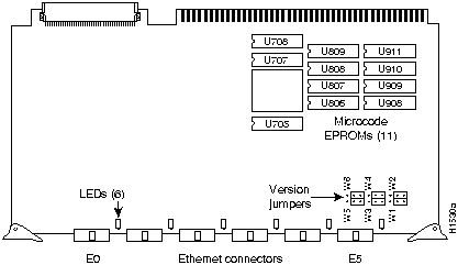
Figure 1 CSC-MEC Card Type 5.1---Component-Side View
Table 2 CSC-MEC Microcode Version 2.4 Component Numbers
| Component Numbers ---Old | New | |||
|---|---|---|---|---|
| Socket | Version 2.1 | Version 2.2 | Version 2.3 | Version. 2.4 |
| U708 | 17-0702 | 17-0702-01 | 17-0702-02 | 17-0702-03 |
| U707 | 17-0704 | 17-0704-01 | 17-0704-02 | 17-0704-03 |
| U705 | 17-0703 | 17-0703-01 | 17-0703-02 | 17-0703-03 |
| U809 | 17-0706 | 17-0706-01 | 17-0706-02 | 17-0706-03 |
| U808 | 17-0707 | 17-0707-01 | 17-0707-02 | 17-0707-03 |
| U807 | 17-0705 | 17-0705-01 | 17-0705-02 | 17-0705-03 |
| U806 | 17-0701 | 17-0701-01 | 17-0701-02 | 17-0701-03 |
| U911 | 17-0700 | 17-0700-01 | 17-0700-02 | 17-0700-03 |
| U910 | 17-0697 | 17-0697-01 | 17-0697-02 | 17-0697-03 |
| U909 | 17-0698 | 17-0698-01 | 17-0698-02 | 17-0698-03 |
| U908 | 17-0699 | 17-0699-01 | 17-0699-02 | 17-0699-03 |
Table 3 CSC-C2MEC Microcode Version 10.3 Component Numbers
| Component Numbers---Old | New | |||||||
|---|---|---|---|---|---|---|---|---|
| Socket | Version 2.1 | Version 2.2 | Version 2.3 | Version 2.4 | Version 10.0 | Version 10.1 | Version 10.2(1) | Version 10.3 |
| U708 | 17-0702 | 17-0702-01 | 17-0702-02 | 17-0702-03 | 17-1329-01 | 17-1329-02 | 17-1329-03 | 17-1329-04 |
| U707 | 17-0704 | 17-0704-01 | 17-0704-02 | 17-0704-03 | 17-1331-01 | 17-1331-02 | 17-1331-03 | 17-1331-04 |
| U705 | 17-0703 | 17-0703-01 | 17-0703-02 | 17-0703-03 | 17-1330-01 | 17-1330-02 | 17-1330-03 | 17-1330-04 |
| U809 | 17-0706 | 17-0706-01 | 17-0706-02 | 17-0706-03 | 17-1333-01 | 17-1333-02 | 17-1333-03 | 17-1333-04 |
| U808 | 17-0707 | 17-0707-01 | 17-0707-02 | 17-0707-03 | 17-1334-01 | 17-1334-02 | 17-1334-03 | 17-1334-04 |
| U807 | 17-0705 | 17-0705-01 | 17-0705-02 | 17-0705-03 | 17-1332-01 | 17-1332-02 | 17-1332-03 | 17-1332-04 |
| U806 | 17-0701 | 17-0701-01 | 17-0701-02 | 17-0701-03 | 17-1328-01 | 17-1328-02 | 17-1328-03 | 17-1328-04 |
| U911 | 17-0700 | 17-0700-01 | 17-0700-02 | 17-0700-03 | 17-1327-01 | 17-1327-02 | 17-1327-03 | 17-1327-04 |
| U910 | 17-0697 | 17-0697-01 | 17-0697-02 | 17-0697-03 | 17-1324-01 | 17-1324-02 | 17-1324-03 | 17-1324-04 |
| U909 | 17-0698 | 17-0698-01 | 17-0698-02 | 17-0698-03 | 17-1325-01 | 17-1325-02 | 17-1325-03 | 17-1325-04 |
| U908 | 17-0699 | 17-0699-01 | 17-0699-02 | 17-0699-03 | 17-1326-01 | 17-1326-02 | 17-1326-03 | 17-1326-04 |
After you reinstall the upgraded MEC card and reconnect the internal ribbon cables, test the installation (before you replace the front panel) by observing the following LED indicators:
The ciscoBus card (CSC-CCTL or CSC-CCTL2) is always installed in the center ciscoBus slot (Multibus slot number 7), as shown in Figure 2. After verifying that the LEDs go on correctly, use the show controller cbus command to display the new microcode version.
The bank of indicators used on the CSC-CCTL is different from that on the CSC-CCTL2. Descriptions of both types of ciscoBus controllers follow. Review them so that you can anticipate how the LED indicators should go on. Before turning on the chassis power to check the installation, note the ciscoBus slot number(s) that contain the MEC card(s) you just reinstalled. (Figure 2 shows the ciscoBus slot numbers and locations.)
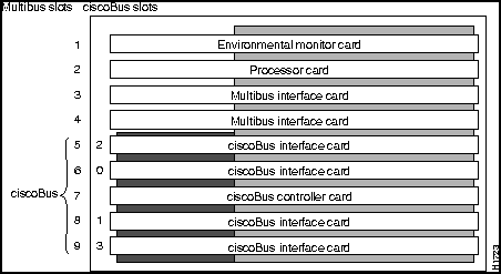
Figure 2 AGS+ Card Cage---Front View
The CSC-CCTL contains a bank of 16 LEDs as shown in Figure 3: four sets of four LEDs, one set for each interface slot in the ciscoBus. Figure 3 shows the LEDs as viewed with the card installed in the card cage---edge on, component-side up. In the illustration, the numbers above each LED indicate the corresponding ciscoBus slot number. (Slot numbers and locations are shown in
Figure 2.) Only the first (far left) LED in each set of four is used as an indicator that goes on when an interface is present in a ciscoBus slot. At power-up, all the LEDs are on, indicating that the CSC-CCTL card is active. When the system boot completes, only those LEDs that indicate the presence of a card in the corresponding ciscoBus slot should be on; the LEDs for empty ciscoBus slots should be off.
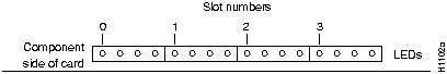
Figure 3 CSC-CCTL Card LED Indicators---Front-Edge View
The CSC-CCTL2 contains a bank of 5 LEDs, one red indicator for each ciscoBus slot and one green OK indicator. Figure 4 shows the indicators as viewed with the card installed in the card cage---edge on, component-side up. In the illustration, the numbers above each LED indicate the corresponding ciscoBus slot number. (Slot numbers and locations are shown in Figure 2.) At power-up, all the LEDs should be on, indicating that the CSC-CCTL2 card is active. When the system boot completes, only those LEDs that indicate the presence of a card in the corresponding ciscoBus slot should remain on; the LEDs for empty ciscoBus slots should be off.
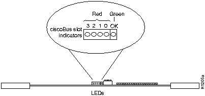
Figure 4 CSC-CCTL2 Card LED Indicators---Front-Edge View
Also observe the LEDs on the MEC card you just reinstalled. An LED is located next to each port, as shown in Figure 5. After the system boots, the LED for each connected port should be on.
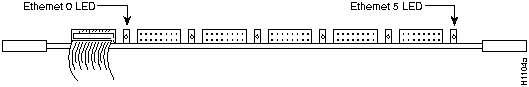
Figure 5 CSC-MEC Card LED Indicators---Front-Edge View
Verify correct installation of the new microcode components with the following steps.
To display the new microcode version, enter the show controller cbus command. The first line of the display for each installed MEC card should indicate the new microcode version, as follows:
cBus 1, controller type 3.0, microcode version 2.0
  [text omitted]
MEC 0, controller type 5.1, microcode version 2.4
ciscoBus 1, controller type 6.0, microcode version 11.0
  [text omitted]
MEC 0, controller type 5.1, microcode version 10.3
After the installation checks out successfully, replace the front access cover and finger-tighten the two thumb fasteners.
This completes the Microcode Version 2.4 or 10.3 upgrade procedure.
tac@cisco.com
. For upgrade or product information, contact the Customer Response Center at 800 553-6387, 415 903-7208, or
cs-rep@cisco.com
.
Cisco Systems' Customer Information Online (CCO) system provides online information and electronic services to Cisco direct customers and business partners. Basic CCO services include general Cisco information, product announcements, descriptions of service offerings, and download access to public and authorized files, including release notes, and software. Maintenance customers receive a much broader offering, including technical notes, the bug database, and electronic mail access to the TAC. (Maintenance customers must have authorization from their Cisco contract administrators to receive these privileges.)
For dialup or Internet users, CCO supports Zmodem, Kermit, Xmodem, FTP PUT, Internet e-mail, Telnet, rlogin, and fax download options. Internet users also can retrieve files from CCO using FTP.
Registration for CCO is handled on line. To reach CCO via the Internet, use Telnet or FTP to
cio.cisco.com
(131.108.89.33). To reach CCO by dialup, use 415 9038070 (Mountain View, California) or 33 1 6446 4082 (Paris, France).
|
|
Copyright 1988-1995 © Cisco Systems Inc.