|
|

Route Switch Processor (RSP2) Installation and Configuration
Product Numbers: RSP2=, RSP2-ROMMON=, MEM-RSP-8M=, MEM-RSP-16M, MEM-RSP-24M, MEM-RSP-32M(=), MEM-RSP-64M(=), and MEM-RSP-128M(=)
This document discusses the second generation Route Switch Processor (RSP2), which is the main processor module for the Cisco 7507 and Cisco 7513 routers. The RSP2 combines all of the switched routing and high-speed switching functions required by the Cisco 7507 and Cisco 7513. For more information, refer to the section "What Is the RSP2?" on page 4.
The RSP2 supports high system availability (HSA), which is a new feature in Cisco IOS Release 11.1(4), or later, that allows two RSP2s to be used simultaneously in a Cisco 7513 or Cisco 7507 router. One RSP2 operates as system master and the other RSP2 operates as the system slave, which takes over if the master RSP2 fails.
RSP2 functionality in the Cisco 7507 and Cisco 7513 is similar. For convenience, the Cisco 7507 and Cisco 7513 routers are referred to as the chassis, with differences clearly noted.
Following are the sections in this document:
The Cisco 7507 is a 7-slot router chassis, which uses the RSP2 and CxBus and CyBus interface processors. The Cisco 7507 provides up to five interface processor slots. Although the Cisco 7507 uses two high-speed, 1.067-gigabit-per-second (Gbps) CyBuses, it can accommodate all CxBus-based interface processors.
Any combination of network interface types is supported: Ethernet, Fast Ethernet, Token Ring, Fiber Distributed Data Interface (FDDI), channel attachment, multichannel, serial, and so forth. The RSP2 and interface processors are keyed with guides on the backplane to prevent them from being fully inserted in the wrong slot.
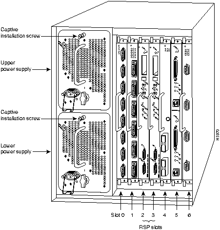
Figure 1 shows the rear of the seven-slot Cisco 7507 router. In the Cisco 7507, up to two slots (2 and 3) are reserved for the Route Switch Processor (RSP2), which contains the system processor and performs packet switching functions. Slots 0 and 1 and 4 through 6 are for interface processors. The five interface processor slots numbered slot 0 (far left) and slot 1 comprise CyBus 0, and slot 4 through slot 6 comprise CyBus 1.
Figure 1 : Cisco 7507, Interface Processor End
The Cisco 7513 is a 13-slot router chassis, which uses the RSP2 and CxBus and CyBus interface processors. The Cisco 7513 provides up to eleven interface processor slots. Although the Cisco 7513 uses two high-speed, 1.067-gigabit-per-second (Gbps) CyBuses, it can accommodate all CxBus-based interface processors.
Any combination of network interface types is supported: Ethernet, Token Ring, Fiber Distributed Data Interface (FDDI), channel attachment, multichannel, serial, and so forth. The RSP2 and interface processors are keyed with guides on the backplane to prevent them from being fully inserted in the wrong slot.
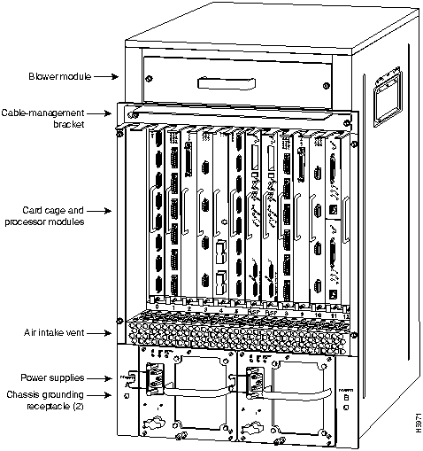
Figure 2 shows the interface processor end of the Cisco 7513, which provides access to the thirteen slots, the system blower, and the power supplies. When facing the interface processor end of the chassis, the RSP2 is installed in RSP slot 6 or 7. The eleven interface processor slots are numbered from slot 0 (far left) through slot 5 (CyBus 0) and slot 8 through slot 12 (CyBus 1).
Figure 2 : Cisco 7513, Interface Processor End
The RSP2 is the main system processor module for the chassis. It combines all of the switched routing and high-speed switching functions of the separate Route Processor (RP) and Switch Processor (SP), which are used in the Cisco 7000 series routers. The RSP2 supports high system availability (HSA), which is a new feature in Cisco IOS Release 11.1(4) or later, that allows two RSP2s to be used in a Cisco 7513 or Cisco 7507 router. By default, the system master is the RSP2 that occupies the first RSP slot in the chassis: slot 2 in the Cisco 7507, and slot 6 in the Cisco 7513.
The RSP2 contains the central processing unit (CPU) and most of the memory components for the chassis. The Cisco Internetwork Operating System (Cisco IOS) software images reside in Flash memory, which is located either on the RSP2, in the form of a single in-line memory module (SIMM), or on up to two Personal Computer Memory Card International Association (PCMCIA) cards (called Flash memory cards) that insert in the two PCMCIA slots (slot 0 and slot 1) on the front of the RSP2. (See Figure 16.)
Storing the Cisco IOS images in Flash memory enables you to download and boot from upgraded Cisco IOS images remotely or from software images resident in the RSP2 Flash memory, without having to remove and replace read-only memory (ROM) devices.
The RSP2 uses a software-controlled configuration register, so you do not have to remove the RSP2 to configure jumpers. There are no user-configurable jumpers on the RSP2.
The RSP2 contains the following components:
In addition to the system software, the RSP2 contains and executes the following management functions that control the system:
The high-speed switching section of the RSP2 communicates with and controls the interface processors on the high-speed CyBus. This switching section decides the destination of a packet and switches it based on that decision. The RSP2 uses a 16-million-instructions-per-second (mips) processor to provide high-speed, autonomous switching and routing.
Figure 3 shows the various types of memory components on the RSP2, and Table 1 lists the functions of each type.
Figure 3 : Route Switch Processor (RSP2), Horizontal Orientation Shown
Table 1 : RSP2 Memory Components
| Type | Size | Quantity | Description | Location |
|---|---|---|---|---|
| DRAM | 16 to 128 MB | 2 to 4 | 8-, 16-, or 32-MB SIMMs (based on maximum DRAM required). | Bank 0: U21 and U33 Bank 1: U12 and U4 |
| NVRAM | 128 KB | 1 | Nonvolatile SRAM for the system configuration file.1 | U18 |
| Flash SIMM
Flash Card |
8 MB
8, 16, and 20 MB2 |
1
Up to 2 |
Contains the Cisco IOS images on the RSP2.
Contains the Cisco IOS images on up to two PCMCIA cards. |
U1
Slot 0 and slot 1 |
| Boot ROM3 | 256 KB | 1 | EPROM for the ROM monitor program. | U30 |
The Cisco 7507 and Cisco 7513 routers support downloadable system software and microcode for most Cisco IOS and microcode upgrades, which enables you to remotely download, store, and boot from a new image. The publication Upgrading Software and Microcode in Cisco 7000 Family Routers (Document Number 78-1144-xx), which accompanies all Cisco IOS upgrade kits, provides instructions for upgrading over the network or from floppy disks. Flash memory contains the default system software. An erasable programmable read-only memory (EPROM) device contains the latest microcode version, in compressed form, for each interface processor. At system startup, an internal system utility scans for compatibility problems between the installed interface processor types and the bundled microcode images, then decompresses the images into running dynamic random-access memory (DRAM). The bundled microcode images then function the same as the EPROM images.
DRAM stores routing tables, protocols, and network accounting applications. The standard RSP2 configuration is 16 megabytes (MB) of DRAM, with up to 128 MB available through SIMM upgrades.
The system configuration, software configuration register settings, and environmental monitoring logs are contained in the 128-KB NVRAM, which is backed up with built-in lithium batteries that retain the contents for a minimum of five years. When replacing an RSP2, be sure to back up your configuration to a remote server so you can retrieve it later.
Both the onboard and PCMCIA card-based Flash memory allow you to remotely load and store multiple Cisco IOS software and microcode images. You can download a new image over the network or from a local server and then add the new image to Flash memory or replace the existing files. You can then boot routers either manually or automatically from any of the stored images. Flash memory also functions as a TFTP server to allow other servers to boot remotely from stored images or to copy them into their own Flash memory.
Before you can use a Flash memory card that was previously used on a Route Processor (RP) in a Cisco 7000 series router, you must reformat the Flash memory card. Flash memory cards formatted on RP-based (Cisco 7000 series) routers will not work properly in RSP-based (Cisco 7500 series) routers.
There are no user-configurable jumpers on the RSP2.
Two LEDs on the RSP2, normal and CPU halt, indicate the system and RSP2 status. The normal LED is on when the system is operational and indicates that the RSP2 is receiving +5V. During normal operation, the CPU halt LED should be off. The CPU halt LED goes on only if the system detects a processor hardware failure. The RSP2 controls both LEDs and turns both on in parallel to indicate that the system is operational. The master/slave LEDs indicate whether an RSP2 is the CyBus master or a slave to the CyBus master.
Two asynchronous serial ports on the RSP2, the console and auxiliary ports, allow you to connect external devices to monitor and manage the system. The console port is an Electronics Industries Association/Telecommunications Industry Association (EIA/TIA)-232 receptacle (female) that provides a data circuit-terminating equipment (DCE) interface for connecting a console terminal.
The auxiliary port is an EIA/TIA-232 plug (male) that provides a data terminal equipment (DTE) interface; the auxiliary port supports flow control and is often used to connect a modem, a channel service unit (CSU), or other optional equipment for Telnet management.
Before beginning any of the procedures in this document, review the following sections to ensure that your equipment configuration meets the minimum requirements for the upgrade or replacement you will perform, and that you have all the parts and tools you will need. Also, review safety and ESD-prevention guidelines to help you to avoid injury or damage to the equipment.
If you are replacing an existing RSP2, back up your current configuration file to a remote server before you remove the RSP2 to avoid having to reenter all your current configuration information manually. To back up the file, you need access to a remote server. Refer to the section "Saving and Retrieving the Configuration File" on page 12, for instructions for uploading the file and retrieving it after the new RSP2 is installed.
This section lists safety guidelines you should follow when working with any equipment that connects to electrical power or telephone wiring.
Follow these basic guidelines when working with any electrical equipment:
Use the following guidelines when working with any equipment that is connected to telephone wiring or to other network cabling:
Preventing Electrostatic Discharge Damage
ESD damage, which can occur when electronic cards or components are improperly handled, can result in complete or intermittent failures. Each processor module contains a printed circuit card that is fixed in a metal carrier. Electromagnetic interference (EMI) shielding, connectors, and a handle are integral components of the carrier. Although the metal carrier helps to protect the board from ESD, use an ESD-preventive wrist or ankle strap whenever you handle any electronic system component.
Following are guidelines for preventing ESD damage:
There are no restrictions on installing an RSP2 in a Cisco 7507 provided that you install the RSP2 in the slot 2 or slot 3. (See the section "What Is the Cisco 7507?" on page 2.) There are no restrictions on installing an RSP2 in a Cisco 7513 provided that you install the RSP2 in the slot 6 or slot 7. (See the section "What Is the Cisco 7513?" on page 3.) You must obtain the replacement SIMMs from an approved vendor. To ensure that you obtain the latest available product and vendor information, obtain the list from one of the following sources:
Although the PCMCIA card and SIMM specifications are defined in the manufacturers' part numbers, they must meet the following requirements:
The RSP2 is compatible with Cisco IOS Release 10.3(571) or later. The HSA feature requires Cisco IOS Release 11.1(4) or later.
The show version and show hardware commands display the current hardware configuration of the router, including the system software version that is currently loaded and running. The show microcode command lists the bundled microcode (target hardware) version for each processor type. The show controller cbus command shows the microcode version you are running. (For complete descriptions of show commands, refer to the Configuration Fundamentals Configuration Guide and Configuration Fundamentals Command Reference publications, which are available on the Cisco Connection Documentation, Enterprise Series CD-ROM or as printed copies.)
You can determine the current version of software or microcode stored in ROM in either of two ways: removing the processor module and checking the ROM labels; configuring the system to boot the system software or microcode from ROM, reloading the system, and using show commands to check the version that is loaded and running. Refer to the appropriate software documentation for complete configuration instructions and examples.
Versatile Interface Processors (VIPs) and second-generation Versatile Interface Processors (VIP2s) can be used in Cisco 7507 and Cisco 7513 routers configured for HSA, if the Cisco 7507 or Cisco 7513 routers are running Cisco IOS Release 11.1(6)CA or later. (For details on the HSA fetaure, refer to the section "Configuring High System Availability Operation" on page 26.)
The minimum required DRAM configuration for the RSP2s in your system is 24 MB. The HSA feature requires that the boot read-only memory (ROM) device (U30, see Figure 3) be updated to Version 11.1(2) or later (RSP2-ROMMON=). New RSP2s are shipping with this new boot ROM version; however, to check the boot ROM (also called the system bootstrap) version currently running on your RSP2, use the show version command and check the boot ROM's version number as follows:
Microcode is a set of processor-specific software instructions that enables and manages the features and functions of a specific processor type. At system startup or reload, the system loads the microcode for each processor type present in the system. The latest available microcode image for each processor type is bundled and distributed with the system software image.
New microcode is released to enable new features, improve performance, or fix bugs in earlier versions. The Cisco routers feature downloadable software and microcode for most upgrades. These features enable you to download new (upgraded) images remotely, store the images in router memory, and load the new images at system startup without having to physically access the router.
You can store multiple versions for a specific processor type in Flash memory, and use configuration commands to specify which version the system should load at startup. All interfaces of the same type (for example, all CIPs) use the same microcode image. Although most upgrades can be downloaded, some exceptions require ROM replacement to ensure proper startup and operation.
Microcode images that are bundled with the system image load automatically along with the new software image, except for the Channel Interface Processor (CIP) microcode image, which is bundled separately.
You need some or all of the following tools and parts to remove and replace an RSP2. If you need additional equipment, contact a customer service representative for ordering information.
Saving and Retrieving the Configuration File
This section describes the procedures for saving (copying) and retrieving the system configuration using a Trivial File Transfer Protocol (TFTP) server.
Configuration information resides in two places when the router is operating: the default startup (permanent) configuration in NVRAM, and the running (temporary) configuration in DRAM. The startup configuration always remains available; NVRAM retains the information even when the power is shut down. The running configuration is lost if the system power is shut down. The startup configuration (in NVRAM) contains all nondefault configuration information that you added with the configure command, the setup command facility, or by editing the configuration file.
The copy running-config startup-config command adds the current configuration to the default configuration in NVRAM, so that it will also be saved when power is shut down. Whenever you make changes to the system configuration, issue the copy running-config startup-config command to ensure that the new configuration is saved.
If you replace the RSP2, in a system with only one RSP2, you also replace the entire configuration (NVRAM resides in socket U18 on the RSP2). If you copy the configuration file to a remote server before removing the RSP2, you can retrieve it later and write it into NVRAM on the new RSP2.
If you do not copy the configuration file, you will have to use the configure command or the setup command facility to reenter the configuration information after you install the new RSP2. For complete descriptions of these commands and instructions for using them, refer to the appropriate software documentation.
The preceding procedure is not necessary if you are temporarily removing an RSP2; the lithium batteries will retain the configuration in memory until you replace the RSP2 in the system. This procedure requires privileged-level access to the EXEC command interpreter, which usually requires a password. Refer to the description that follows and contact your system administrator to obtain access, if necessary.
Using the EXEC Command Interpreter
Before you use the configure command, you must enter the privileged level of the EXEC command interpreter using the enable command. The system prompts you for a password if one has been set.
The system prompt for the privileged level ends with a pound sign (#) instead of an angle bracket (>). At the console terminal, enter the privileged level as follows:
The pound sign (#) at the system prompt indicates that you are at the privileged level of the EXEC command interpreter; you can now execute the EXEC-level commands that are described in the following sections.
Before you attempt to copy or retrieve a file from a remote host, ensure that the connection is good between the router and the remote server, by using the packet internet groper (ping) program. The ping program sends a series of echo request packets to the remote device and waits for a reply. If the connection is good, the remote device echoes them back to the local device.
The console terminal displays the results of each message sent: an exclamation point (!) indicates that the local device received an echo, and a period (.) indicates that the server timed out while awaiting the reply. If the connection between the two devices is good, the system displays a series of exclamation points (! ! !) or [ok]. If the connection fails, the system displays a series of periods (. . .) or [timed out] or [failed].
To verify the connection between the router and a remote host, issue the ping command followed by the name or Internet Protocol (IP) address of the remote server; then press Return. Although the ping command supports configurable options, the defaults, including IP as the protocol, are enabled when you enter a host name or address on the same line as the ping command. For a description of the configurable options, refer to the appropriate software documentation.
The following example shows a successful ping operation:
The following example shows the results of a failed ping operation:
If the connection fails, check the physical connection to the remote file server and verify that you are using the correct address or name, then ping the server again. If you are unable to establish a good connection, contact your network administrator or refer to the end of this document for instructions on contacting technical assistance.
Copying the Configuration File
Before you copy the running configuration to the TFTP file server, ensure the following:
To store information on a remote host, enter the copy startup-config tftp privileged EXEC command. The command prompts you for the destination host's address and a filename, then displays the instructions for confirmation. When you confirm the instructions, the router sends a copy of the currently running configuration to the remote host. The system default is to store the configuration in a file called by the name of the router with -confg appended. You can either accept the default filename by pressing Return at the prompt, or enter a different name before pressing Return.
Follow these steps to copy the currently running configuration to a remote host:
After you copy the configuration file, proceed to the following section "Retrieving the Configuration File," after you have replaced the boot ROM and reinstalled the RSP2. If you are unable to copy the configuration file to a remote host successfully, contact your network administrator or refer to the end of this document for instructions on contacting technical assistance.
Retrieving the Configuration File
After you reinstall the RSP2, you can retrieve the saved configuration and copy it back to NVRAM. To retrieve the configuration, enter configuration mode and specify that you will configure the router from the network. The system prompts you for a host name and address, the name of the configuration file stored on the host, and confirmation to reboot using the remote file.
Follow these steps to retrieve the currently running configuration from a remote host:
This completes the procedure for retrieving the saved configuration file.
The following sections describe the procedures for installing or replacing an RSP2. Ensure that your system meets the minimum software, hardware, and microcode requirements described in the sections "Software Prerequisites" on page 10, "Hardware Prerequisites" on page 11, and "Microcode Requirements" on page 11. Proceed to the section "Removing the RSP2" for instructions on removing the RSP2, and then to the section "Replacing the RSP2" for the installation instructions. After the new RSP2 is secure, follow the procedures in the section "Troubleshooting the Installation" on page 42 to verify that it is installed and functioning properly.
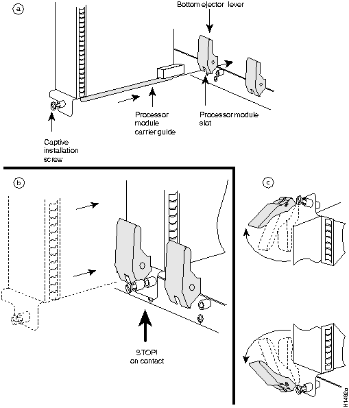
When you remove or install the RSP2, be sure to use the ejector levers, which help to ensure that the RSP2 is fully inserted in the backplane or fully dislodged from it. An RSP2 that is only partially connected to the backplane can halt the system, unless a second RSP2 is installed. Figure 4 on page 20 shows a detail of the ejector lever mechanism in a horizontal position that is appropriate for the chassis. When you simultaneously push the ejector levers inward (toward the carrier handle), the levers push the RSP2 into the slot and ensure that the board connectors are fully seated in the backplane. Follow these steps to remove the RSP2:
This completes the removal procedure. If you removed the RSP2 to replace SIMMs, proceed to the appropriate section. If you are replacing the RSP2, proceed to the next section to install the new RSP2.
The RSP2 is keyed for installation only in an RSP2 slot. (See Figures 1 and 2.) By default, the system master is the RSP2 that occupies the first RSP slot in the chassis: slot 2 in the Cisco 7507, and slot 6 in the Cisco 7513. Follow these steps to install an RSP2:
Figure 4 : Ejector Levers and Captive Installation Screw
Connecting the Console Terminal
The system console port on the RSP2 is a DCE DB-25 receptacle for connecting a data terminal, which you will need to configure and communicate with your system. The console port is located on the RSP2 to the right of the auxiliary port and is labeled Console, as shown in Figure 5.
Before connecting the console port, check your terminal's documentation to determine the baud rate of the terminal you will be using. The baud rate of the terminal must match the default baud rate (9600 baud). Set up the terminal as follows: 9600 baud, 8 data bits, no parity, and 2 stop bits (9600,8N2)
Use the console cable provided to connect the terminal to the console port on the RSP2, then follow the steps in the section "Restarting the System" on page 23.
Figure 5 : Console and Auxiliary Port Connections
Connecting to the Auxiliary Port
The auxiliary port on the RSP2 is a DB-25 plug DTE port for connecting a modem or other DCE device (such as a CSU/DSU or other router) to the router. The port is located above the console port on the RSP2 and is labeled Auxiliary. An example of a modem connection is shown in Figure 5.
Using the Y-Cables for Console and Auxiliary Connections
For systems with two RSP2s installed (one as master and one as slave in RSP slots 6 and 7, using the HSA feature), you can simultaneously connect to both console or auxiliary ports using a special Y-cable. RSP2 defaults as the system masters if only one is installed. Figure 6 shows the console Y-cable and Figure 7 shows the auxiliary Y-cable.
When you turn the system power back on, verify that the system boots and resumes normal operation. If you are restarting the system after upgrading the DRAM, expect that it will take the system longer to complete the memory initialization portion of the boot sequence with more DRAM. (See the section "System Startup Sequence" on page 44.)
Follow these steps to verify that the RSP2 is installed and functioning properly:
When you have verified all the conditions in Steps 2 through 6 (or Step 7 if you have a second RSP2 installed and want to use the HSA feature), the installation is complete. If you replaced the RSP2 and saved your configuration file to a remote server before doing so, proceed to the section "Retrieving the Configuration File" on page 16. If you replaced the RSP2 and did not save the configuration, use the configure command or the setup command facility to reenter the configuration information.
An error condition exists if no LEDs go on at power up or after initialization, or if the boot error or CPU halt LEDs go on and remain on. If this happens, proceed to the following section "Troubleshooting the Installation" to try to isolate the problem. For more complete configuration information, refer to the Configuration Fundamentals Configuration Guide and the Configuration Fundamentals Command Reference publications, which are available on the Cisco Connection Documentation, Enterprise Series CD-ROM or as printed copies.
If you have a second RSP2 installed, you must configure the HSA feature for your Cisco 7507 or Cisco 7513 router. Read the following caution, then proceed to the following section "Configuring High System Availability Operation."
Configuring High System Availability Operation
High system availability (HSA) (available with Cisco IOS Release 11.1[4] or later) refers to how quickly your router returns to an operational status after a failure occurs.
On the Cisco 7507 and Cisco 7513, you can install two RSP2 cards in a single router to improve system availability. For more complete HSA configuration information, refer to the Configuration Fundamentals Configuration Guide and the Configuration Fundamentals Command Reference publications, which are available on the Cisco Connection Documentation, Enterprise Series CD-ROM or as printed copies.
Two RSP2 cards in a router provide the most basic level of increased system availability through a "cold restart" feature. A "cold restart" means that when one RSP2 card fails, the other RSP2 card reboots the router. In this way, your router is never in a failed state for very long, thereby increasing system availability.
When one RSP2 card takes over operation from another, system operation is interrupted. Such a change is similar to issuing the reload command. The following events occur when one RSP2 card fails and the other takes over:
A router configured for HSA operation has one RSP2 card that is the master and one that is the slave. The master RSP2 card functions as if it were a single processor, controlling all functions of the router. The slave RSP2 card does nothing but actively monitor the master for failure. A system crash can cause the master RSP2 to fail or go into a nonfunctional state. When the slave RSP2 detects a nonfunctional master, the slave resets itself and takes part in master-slave arbitration. Master-slave arbitration is a ROM monitor process that determines which RSP2 card is the master and which is the slave upon startup (or reboot).
If a system crash causes the master RSP2 to fail, the slave RSP2 becomes the new master RSP2 and uses its own system image and configuration file to reboot the router. The failed RSP2 card (now the slave) remains inactive until you perform diagnostics, correct the problem, and then issue the slave reload command.
With HSA operation, the following items are important to note:
There are two common ways to use HSA as follows:
You can also use HSA for advanced implementations. For example, you can configure the RSP2 cards with the following:
For the high system availability (HSA) feature to operate properly, the following prerequisites must be observed:
Configure HSA Operation Task List
When configuring HSA operation, complete the tasks in the following sections. The first is required. Depending on the outcome of the first, the second or third is also required. The fourth and fifth are optional.
Determining the HSA Implementation Method to Use
Before you can configure HSA operation, you must first decide how you want to use HSA in your internetwork. Do you want to use HSA for simple hardware backup or for software error protection? If you are using new or experimental Cisco IOS software, consider using the software error protection method; otherwise, use the simple hardware backup method.
Once you have decided which method to use, proceed to either the "Configuring HSA for Simple Hardware Backup" section or the "Configuring HSA for Software Error Protection" section.
Configuring HSA for Simple Hardware Backup
With the simple hardware backup method, you configure both RSP2 cards with the same software image and configuration information. To configure HSA for simple hardware backup, perform the tasks in the following sections. The first is optional.
Specifying the Default Slave RSP2
Because your view of the environment is always from the master RSP2's perspective, you define a default slave RSP2. The router uses the default slave information when booting:
To define the default slave RSP2, perform the following task, beginning in global configuration mode:
Upon the next system reboot, the above changes take effect (if both RSP2 cards are operational). Thus, the specified default slave becomes the slave RSP2 card. The other RSP2 card takes over mastership of the system and controls all functions of the router.
If you do not specifically define the default slave RSP2, the RSP2 card located in the higher number processor slot is the default slave. On the Cisco 7507, processor slot 3 contains the default slave RSP2. On the Cisco 7513, processor slot 7 contains the default slave RSP2.
The following example sets the default slave RSP2 to processor slot 2 on a Cisco 7507:
Ensuring That Both RSP2 Cards Contain the Same Images
To ensure that both RSP2 cards have the same system image, perform the following tasks in EXEC mode:
The following example ensures that both RSP2 cards have the same system image. Note that because no environment variables are set, the default environment variables are in effect for both the master and slave RSP2.
To ensure that both RSP2 cards have the same microcode images, perform the following tasks beginning in privileged EXEC mode:
The following example ensures that both RSP2 cards have the same microcode image. Notice that slots 0, 1, 4, 9, and 10 load microcode from the bundled software, as noted by the statement software loaded from system. Slot 11, the FSIP processor, does not use the microcode bundled with the system. Instead, it loads the microcode from slot0:pond/bath/rsp_fsip20-1 Ensuring That Both RSP2 Cards Contain the Same Configuration File
With the simple hardware backup and software error protection implementation methods, you always want your master and slave configuration files to match. To ensure that they match, turn on automatic synchronization. In automatic synchronization mode, the master copies its startup configuration to the slave's startup configuration when you issue a copy command that specifies the master's startup configuration (startup-config) as the target.
Automatic synchronization mode is on by default; however, to turn it on manually, perform the following tasks, beginning in global configuration mode:
The following example turns on automatic configuration file synchronization:
Configuring HSA for Software Error Protection
With the software error protection method, you configure the RSP2 cards with different software images, but with the same configuration information. To configure HSA for software error protection, perform the tasks in the following sections. The first is optional.
Specifying Different Startup Images for the Master and Slave RSP2
When the factory sends you a new Cisco 7507 or Cisco 7513 with two RSPs, you receive the same system image on both RSP2 cards. For the software error protection method, you need two different software images on the RSP2 cards. Thus, you copy a desired image to the master RSP2 card and modify the boot system commands to reflect booting two different system images. Each RSP2 card uses its own image to boot the router when it becomes the master.
To specify different startup images for the master and slave RSP2, perform the following tasks, beginning in EXEC mode:
In the following example scenario, assume the following:
Figure 8 illustrates the software error protection configuration for this example scenario. The configuration commands for this configuration follow the figure.
Figure 8 : Software Error Protection: Upgrading to a New Software Version
Because you always view the environment from the master RSP2's perspective, in the following command you view the master's slot 0 to verify the location and version of the master's software image:
Now view the slave's software image location and version:
Because you want to run the Release 11.2 system image on one RSP2 card and the Release 11.1 system image on the other RSP2 card, copy the Release 11.2 system image to the master's slot 0:
Enter global configuration mode and configure the system to boot first from a Release 11.2 system image and then from a Release 11.1 system image.
With this configuration, when the slot 6 RSP2 card is master, it looks first in its PCMCIA slot 0 for the system image file rsp-jv-mz11.2 to boot. Finding this file, the router boots from that system image. When the slot 7 RSP2 card is master, it also looks first in its slot 0 for the system image file rsp-jv-mz11.2 to boot. Because that image does not exist in that location, the slot 7 RSP2 card looks for the system image file rsp-jv-mz11.1 in slot 0 to boot. Finding this file in its PCMCIA slot 0, the router boots from that system image. In this way, each RSP2 card can reboot the system using its own system image when it becomes the master RSP2 card.
Configure the system further with a fault-tolerant booting strategy:
Set the configuration register to enable loading of the system image from a network server or from Flash and save the changes to the master and slave startup configuration file:
Reload the system so that the master RSP2 uses the new Release 11.2 system image:
In the following example scenario, assume the following:
In this scenario, you begin with the configuration shown in Figure 9.
Figure 9 : Software Error Protection: Backing Up with an Older Software Version, Part I
Next, you copy the rsp-jv-mz11.1 image to the master and slave RSP2 card, as shown in Figure 10.
Figure 10 : Software Error Protection: Backing Up with an Older Software Version, Part II
Last, delete the rsp-jv-mz11.2 image from the slave RSP2 card as shown in Figure 11:
Figure 11 : Software Error Protection: Backing Up with an Older Software Version, Part III
The following commands configure software error protection for this example scenario.
View the master and slave slot 0 to verify the location and version of their software images:
Copy the Release 11.1 system image to the master and slave slot 0:
Delete the rsp-jv-mz11.2 image from the slave RSP2 card:
Configure the system to boot first from a Release 11.2 system image and then from a Release 11.1 system image.
Configure the system further with a fault-tolerant booting strategy:
Set the configuration register to enable loading of the system image from a network server or from Flash and save the changes to the master and slave startup configuration file:
Setting Environment Variables on the Master and Slave RSP2
You can optionally set environment variables on both RSP2 cards in a Cisco 7507 and Cisco 7513.
You set environment variables on the master RSP2 just as you would if it were the only RSP2 card in the system. You can set the same environment variables on the slave RSP2 card, manually or automatically.
The following sections describe these two methods:
For more complete configuration information on how to set environment variables, refer to the Configuration Fundamentals Configuration Guide and the Configuration Fundamentals Command Reference publications, which are available on the Cisco Connection Documentation, Enterprise Series CD-ROM or as printed copies.
Manually Setting Environment Variables on the Slave RSP2
Once you set the master's environment variables, you can manually set the same environment variables on the slave RSP2 card using the slave sync config command.
To manually set environment variables on the slave RSP2, perform the following steps beginning in global configuration mode:
Automatically Setting Environment Variables on the Slave RSP2
With automatic synchronization turned on, the system automatically saves the same environment variables to the slave's startup configuration when you set the master's environment variables and save them.
To set environment variables on the slave RSP2 when automatic synchronization is on, perform the following steps beginning in global configuration mode:
Monitoring and Maintaining HSA Operation
To monitor and maintain HSA operation, you can override the slave image that is bundled with the master image. To do so, perform the following task in global configuration mode:
You can manually synchronize configuration files and ROM monitor environment variables on the master and slave RSP2 card. To do so, perform the following task in privileged EXEC mode:
The slave sync config command is also a useful tool for more advanced implementation methods not discussed in this document. Refer to the Configuration Fundamentals Configuration Guide and the Configuration Fundamentals Command Reference publications, which are available on the Cisco Connection Documentation, Enterprise Series CD-ROM or as printed copies.
Troubleshooting the Installation
This section contains procedures to follow if the system does not restart and boot up as expected. Review the descriptions that follow so you can anticipate the expected system startup sequence. Then restart the system and try to isolate the problem by observing the LEDs as the system attempts to boot the software and initialize the RSP2(s) and each interface processor.
Following are functional descriptions of the LEDs on the power supplies and processor modules, and the behavior you should observe at system startup.
On the chassis, the AC (or DC) OK LED is located on each power supply. If this LED does not go on and stay on, there is most likely a problem with the input power or one of the internal DC lines.
The AC (or DC) OK LED will not go on or will go off if the power supply reaches an out-of-tolerance temperature or voltage condition. It is unlikely that the power supply will shut down during startup because of an overtemperature condition; however, it can shut down if it detects an over or undervoltage condition during startup. For descriptions of environmental monitoring functions, refer to the Cisco 7507 Hardware Installation and Maintenance or Cisco 7513 Hardware Installation and Maintenance publications, on the Cisco Connection Documentation, Enterprise Series CD-ROM or in print.
Figure 12 shows the LEDs on the RSP2 faceplate. The LEDs on the RSP2 indicate the system and RSP2 status and which Flash memory card slot is active. The CPU halt LED, which goes on only if the system detects a processor hardware failure, should remain off. A successful boot is indicated when the normal LED goes on; however, this does not necessarily mean that the system has reached normal operation. During normal operation, the CPU halt LED should be off, and the normal LED should be on, indicating that the RSP2 is receiving +5V. The slot 0 and slot 1 LEDs indicate which PCMCIA (Flash memory) card slot is in use, and each LED blinks when the card is accessed by the system.
If you did not install a new boot ROM device correctly, the corresponding RSP2 is placed in a "non-participant" mode and both of its slave and master LEDs will be on. This can be caused by a bent boot ROM pin, a misaligned boot ROM, or a misprogrammed boot ROM. If this condition occurs, power down the system and verify that the boot ROM device is installed. If the boot ROM device was installed backwards, severe damage may have resulted rendering the boot ROM device unusable. You will have to install a new boot ROM device.
Figure 12 : RSP2 LEDs, Master/Slave Switch, and Reset Switch
Each interface processor contains an enabled LED. The enabled LED goes on to indicate that the interface processor is operational and that it is powered up. It does not necessarily mean that the interface ports on the interface processors are functional or enabled. When the boot sequence is complete, all the enabled LEDs should go on.
If any do not, one of the following errors is indicated:
By checking the state of the LEDs, you can determine when and where the system failed in the startup sequence. Because you turn on the system power with the on/off switches on each power supply, it is easiest to observe the startup behavior from the rear of the chassis. Use the following descriptions of the normal startup sequence to isolate the problem, then use the troubleshooting procedures wherever the system fails to operate as expected. If you are able to isolate the problem to a faulty hardware component, or if you are unable to successfully restart the system, refer to the end of this document for instructions on contacting a service representative.
During the boot sequence, the system banner display pauses while it initializes the memory. If your router has more than 16 MB of DRAM, you may notice an increase in the amount of time required to initialize the memory. The pause in the banner display occurs after the copyright line, and before the system displays the list of installed hardware, as shown in the following display:
Use the following startup sequences and troubleshooting procedures to isolate system problems:
If the system still fails to start up or operate properly, or if you isolate the cause of the problem to a failed component, contact a service representative for further assistance.
This completes the RSP2 installation and replacement procedure. For complete command descriptions and examples, refer to the Configuration Fundamentals Command Reference publication.
When a new master RSP2 takes over mastership of the router, it automatically reboots the failed RSP2 as the slave RSP2. You can access the state of the failed RSP2 in the form of a stack trace from the master console using the show stacks command.
You can also manually reload a failed RSP2 from the master console. To do so, perform the following task from global configuration mode:
Displaying Information About the Master and Slave RSP2
You can also display information about both the master and slave RSP2s. To do so, perform any of the following tasks from EXEC mode:
Following is reference information for replacing SIMMs, configuring the software configuration register, recovering a lost password, and using the front-panel PCMCIA slots for additional Flash memory.
The console port on the RSP2 is an EIA/TIA-232, DCE, DB-25 receptacle. Both DSR and DCD are active when the system is running. The RTS signal tracks the state of the CTS input. The console port does not support modem control or hardware flow control. The console port requires a straight-through EIA/TIA-232 cable. Table 2 lists the signals used on this port.
Table 2 : Console Port Signals
The auxiliary port on the RSP2 is an EIA/TIA-232 DTE, DB-25 plug to which you can attach a CSU/DSU or other equipment in order to access the router from the network. The asynchronous auxiliary port supports hardware flow control and modem control. Table 3 lists the EIA/TIA-232 signals used on this port.
Table 3 : Auxiliary Port Signals
Console and Auxiliary Y-Cable Pinouts
The console and auxiliary Y-cables allow you to simultaneously connect the console ports or auxiliary ports on two RSP2s (configured as system master and slave in RSP slots 6 and 7) to one console terminal or external auxiliary device (such as a modem, and so forth).
The two cables (CAB-RSP2CON= and CAB-RSP2AUX=) ship with the chassis and are available as spare parts. The console Y-cable pinouts are listed in Table 4, and the auxiliary Y-cable pinouts are listed in Table 5.
Table 4 : Console Y-Cable Signals (CAB-RSP2CON=)
Table 5 : Auxiliary Y-Cable Signals (CAB-RSP2AUX=)
Replacing and Upgrading DRAM SIMMs
This section describes the steps for increasing the amount of DRAM by replacing up to four SIMMs that you obtain from an approved vendor. The system DRAM resides on up to four SIMMs on the RSP2. The DRAM SIMM sockets are U21 and U33 for bank 0, and U4 and U12 for bank 1. (See Figure 13 and Table 6.) The default DRAM configuration is 16 MB (two 8-MB SIMMs in bank 0).
The SIMM sockets use thumb tabs that are often used in PCs and other computer equipment. Each RSP2 SIMM socket has two metal retaining springs, one at each end. (See Figure 14 on page 52.) When a SIMM is fully seated in the socket, the retaining springs snap over the ends of the SIMM to lock it in the socket.
Before proceeding, ensure that you have the proper tools and ESD-prevention equipment available. To upgrade DRAM, you install SIMMs in one or two banks. Table 6 lists the various configurations of DRAM SIMMs that are available. Note which banks are used given the combinations of available SIMM sizes and the maximum DRAM you require.
Table 6 : DRAM SIMM Configurations
Place removed SIMMs on an antistatic mat and store them in an antistatic bag. You can use the SIMMs that you remove in compatible equipment.
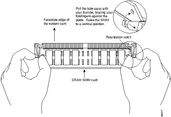
Follow these steps to remove the existing SIMMs:
Figure 14 : Releasing the SIMM Spring Clips
This completes the SIMM removal procedure. Proceed to the next section to install the new SIMMs.
Following is the procedure for installing new SIMMs.
Follow these steps to install the new SIMMs:
If the system fails to boot properly, or if the console terminal displays a checksum or memory error, check the following:
If after several attempts the system fails to restart properly, contact a service representative for assistance. Before you call, make note of any error messages, unusual LED states, or any other indications that might help solve the problem.
This completes the SIMM replacement procedure.
To replace the RSP2 in the chassis, proceed to the section "Replacing the RSP2" on page 19, and then restart the system for an installation check.
Software Configuration Register Settings
Settings for the 16-bit software configuration register are written into the NVRAM. Following are some reasons for changing the software configuration register settings:
Table 7 on page 55 lists the meaning of each of the software configuration memory bits, and Table 8 on page 55 defines the boot field.
Table 7 : Software Configuration Register Bit Meanings
Table 8 : Explanation of Boot Field (Software Configuration Register Bits 00 to 03)
To change the configuration register while running the system software, follow these steps:
The lowest four bits of the software configuration register (bits 3, 2, 1, and 0) form the boot field. (See Table 8.) The boot field specifies a number in binary form. If you set the boot field value to 0, you must boot the operating system manually by entering the b command at the bootstrap prompt, as follows:
Definitions of the various b command options follow:
For more information about the b [tftp] flash [filename] command, refer to the set of configuration fundamentals publications.
If you set the boot field value to 0x2 through 0xF and there is a valid boot system command stored in the configuration file, then the router boots the system software as directed by that value. If you set the boot field to any other bit pattern, the router uses the resulting number to form a default boot filename for booting from a network server. (See Table 9.)
In the following example, the software configuration register is set to boot the router from onboard Flash memory and to ignore Break at the next reboot of the router:
The server creates a default boot filename as part of the automatic configuration processes. To form the boot filename, the server starts with the name cisco and adds the octal equivalent of the boot field number, a hyphen, and the processor-type name. Table 9 lists the default boot filenames or actions for the processor.
Table 9 : Default Boot Filenames
Bit 8 controls the console Break key. Setting bit 8 (the factory default) causes the processor to ignore the console Break key. Clearing bit 8 causes the processor to interpret the Break key as a command to force the system into the bootstrap monitor, thereby halting normal operation. A break can be sent in the first 60 seconds while the system reboots, regardless of the configuration settings.
Bit 9 controls the secondary bootstrap program function. Setting bit 9 causes the system to use the secondary bootstrap; clearing bit 9 causes the system to ignore the secondary bootstrap. The secondary bootstrap program is used for system debugging and diagnostics.
Bit 10 controls the host portion of the IP broadcast address. Setting bit 10 causes the processor to use all zeros; clearing bit 10 (the factory default) causes the processor to use all ones. Bit 10 interacts with bit 14, which controls the network and subnet portions of the broadcast address.
Table 10 : Configuration Register Settings for Broadcast Address Destination
Bits 11 and 12 in the configuration register determine the baud rate of the console terminal. Table 11 shows the bit settings for the four available baud rates. (The factory-set default baud rate is 9600.)
Table 11 : System Console Terminal Baud Rate Settings
Bit 13 determines the server response to a bootload failure. Setting bit 13 causes the server to load operating software from Flash memory after five unsuccessful attempts to load a boot file from the network. Clearing bit 13 causes the server to continue attempting to load a boot file from the network indefinitely. By factory default, bit 13 is cleared to 0.
Enabling Booting from Flash Memory
To enable booting from Flash memory, set configuration register bits 3, 2, 1, and 0 to a value between 2 and 15 in conjunction with the boot system flash device:filename configuration command, where device is bootflash:, slot0:, or slot1:, and filename is the name of the file from which you want to boot the system.
To enter configuration mode while in the system software image and specify a Flash filename from which to boot, enter the configure terminal command at the enable prompt, as follows:
To disable Break and enable the boot system flash device:filename command, enter the config-register command with the value shown in the following example:
Copying a new image to Flash memory might be required whenever a new image or maintenance release becomes available. You cannot copy a new image into Flash memory while the system is running from Flash memory.
Use the command copy tftp:filename [ bootflash: | slot0: | slot1: ]:filename for the copy procedure, where tftp:filename is the source of the file and [ bootflash: | slot0: | slot1: ]:filename is the destination in onboard Flash memory or on either of the Flash memory cards.
An example of the copy tftp:filename command follows:
Additional Commands Associated to Flash Memory
Following are additional commands related to the Flash memory on the RSP2 and the Flash memory cards. You can determine which memory media you are accessing using the pwd command, as follows:
You can move between Flash memory media using the cd [bootflash | slot0 | slot1 ] command, as follows:
You can list the directory of Flash memory media using the dir [bootflash | slot0 | slot1 ] command, as follows:
You can delete a file from any Flash memory media using the delete command, as follows:
Files that are deleted are simply marked as deleted, but still occupy space in Flash memory. The squeeze command removes them permanently and pushes all other undeleted files together to eliminate spaces between them.
Following is the syntax of the squeeze command:
To prevent loss of data due to sudden power loss, the "squeezed" data is temporarily saved to another location of Flash memory, which is specially used by the system.
In the preceding command display output, the character "e" means this special location has been erased (which must be performed before any write operation). The character "b" means that the data that is about to be written to this special location has been temporarily copied. The character "E" signifies that the sector which was temporarily occupied by the data has been erased. The character "S" signifies that the data was written to its permanent location in Flash memory.
The squeeze command operation keeps a log of which of these functions has been performed so upon sudden power failure, it can return to the correct place and continue with the process. The character "Z" means this log was erased after the successful squeeze command operation.
The configuration register setting 0x0101 tells the system to boot the default image (the first image) from onboard Flash memory, but not reset the Break disable or check for a default netboot filename. The configuration register setting 0x0102 tells the system to boot from Flash memory if netboot fails, disable Break, and check for a default netboot filename. For more information on the copy tftp:filename [flash | slot0 | slot1 ]:filename command, and other related commands, refer to the set of configuration fundamentals configuration and reference publications.
An overview of recovering a lost password follows:
To recover a lost password, follow these procedures.
This completes the procedure for recovering from a lost password.
The Flash memory (PCMCIA) card slots on the front panel of the RSP2 are for additional PCMCIA-based Flash memory for your system. You can use this Flash memory to store and run Cisco IOS images, or as a file server for other routers to access as clients. Occasionally, it might be necessary to remove and replace Flash memory cards; however, removing Flash memory cards is not recommended after the cards are installed in the slots.
It might become necessary to replace or install a Flash memory card in your RSP2. The RSP2 has two PCMCIA slots: slot 0 (left) and slot 1 (right). (See Figure 16.) The following procedure is a generic one and can be used for a Flash memory card in either slot position.
Following is the procedure for installing and removing a Flash memory card:
Figure 16 : Installing and Removing a Flash Memory Card
Formatting a Flash Memory Card
The Flash memory card that shipped with your chassis contains the Cisco IOS software image you need to boot your router. In some cases, you might need to insert a new Flash memory card and copy images or backup configuration files onto it. Before you can use a new Flash memory card, you must format it. Before you can use a Flash memory card that was previously used on a Route Processor (RP) in a Cisco 7000 series router, you must reformat the Flash memory card. Flash memory cards formatted on RP-based (Cisco 7000 series) routers will not work properly in RSP-based (Cisco 7500 series) routers.
Use the following procedure to format a new Flash memory card:
The new Flash memory card is now formatted and ready to use.
Making the Flash Memory Card Image Bootable
Use the following series of commands to make the image (the file named new.image) bootable. Note that, since the configuration register must be set to 0x2102, the config-register command is part of the sequence.
When the system reloads it will boot the image new.image from the Flash memory card in slot 0.
Copying a Bootable Image into a Flash Memory Card
With the Flash memory card formatted, you can now copy a bootable image into it. To copy an image, use the following procedure, which assumes the following:
Following is the procedure for copying a bootable file (called new.image) into the Flash memory card:
![]()
![]()
tac@cisco.com
.
to
cs-rep@cisco.com
.
Router# sh version
(display text omitted)
System Bootstrap, Version 11.1(2)
![]()
![]()
Router>
enable
Password:
Router#
Router# ping 1.1.1.1
Type escape sequence to abort.
Sending 5, 100-byte ICMP Echos to 1.1.1.1, timeout is 2 seconds:
!!!!!
Success rate is 100 percent (5/5), round-trip min/avg/max = 12/12/12 ms
Sending 5, 100-byte ICMP Echos to 1.1.1.1, timeout is 2 seconds:
.....
Success rate is 0 percent (0/5)
Router#
Router#
copy startup-config tftp
Remote host []?
Router#
copy startup-config tftp
Remote host []?
servername
Translating "servername"...domain server (1.1.1.1) [OK]
Name of configuration file to write [Router-confg]?
Write file Router-confg on host 1.1.1.1? [confirm]
Writing Router-confg .....
Write file Router-confg on host 1.1.1.1? [confirm]
Writing Router-confg: !!!! [ok]
Writing Router-confg .....
Router#
show startup-config
>> Using 1186 out of 126968 bytes
!
version 11.1
hostname Router
Router#
Router#
copy tftp startup-config
Address of remote host [255.255.255.255]?
1.1.1.1
Name of configuration file [Router-confg]?
Router-confg
Name of configuration file [Router-confg]?
Configure using Router-confg from 1.1.1.1? [confirm]
Loading Router-confg from 1.1.1.1: ! ! [OK - 1186/126927 bytes]
Warning: distilled config is not generated
[OK]
%SYS-5-CONFIG_NV: Non-volatile store configured from Router-confg

by console tftp from 1.1.1.1
Booting Router-confg ..... [timed out]
Router#
show startup-config
Using 1186 out of 126968 bytes
!
version 11.1
hostname Router
!
Router#
Router#
copy startup-config running-config
Router#
%SYS-5-CONFIG_I: Configured from memory by console
Router#
![]()
![]()
System Bootstrap, Version 11.1(2), RELEASED SOFTWARE
Copyright (c) 1986-1996 by cisco Systems, Inc.
SLOT 6 RSP2 is system master
SLOT 7 RSP2 is system slave
RSP2 processor with 16384 Kbytes of main memory
[additional displayed text omitted from this example]
Cisco Internetwork Operating System Software
IOS (tm) GS Software (RSP-JV), Version 11.1(4) [biff 51096]
Copyright (c) 1986-1996 by cisco Systems, Inc.
Compiled Mon 22-Jan-96 21:15 by biff
Image text-base: 0x600108A0, data-base: 0x607B8000
cisco RSP2 (R4600) processor with 16384K bytes of memory.
R4600 processor, Implementation 32, Revision 2.0
[additional displayed text omitted from this example]
8192K bytes of Flash PCMCIA card at slot 0 (Sector size 128K).
8192K bytes of Flash internal SIMM (Sector size 256K).
Slave in slot 7 is halted.
[additional displayed text omitted from this example]
System Bootstrap, Version 11.1(2), RELEASED SOFTWARE
Copyright (c) 1986-1996 by cisco Systems, Inc.
SLOT 2 RSP2 is system master
SLOT 3 RSP2 is system slave
RSP2 processor with 16384 Kbytes of main memory
[additional displayed text omitted from this example]
Cisco Internetwork Operating System Software
IOS (tm) GS Software (RSP-JV), Version 11.1(4) [biff 51096]
Copyright (c) 1986-1996 by cisco Systems, Inc.
Compiled Mon 22-Jan-96 21:15 by biff
Image text-base: 0x600108A0, data-base: 0x607B8000
cisco RSP2 (R4600) processor with 16384K bytes of memory.
R4600 processor, Implementation 32, Revision 2.0
[additional displayed text omitted from this example]
8192K bytes of Flash PCMCIA card at slot 0 (Sector size 128K).
8192K bytes of Flash internal SIMM (Sector size 256K).
Slave in slot 3 is halted.
[additional displayed text omitted from this example]
System Bootstrap, Version 11.1(2) [biff 51096], RELEASED SOFTWARE
Copyright (c) 1994-1996 by cisco Systems, Inc.
SLOT 6 RSP2 is system master
RSP2 processor with 16384 Kbytes of main memory
[additional displayed text omitted from this example]
Cisco Internetwork Operating System Software
IOS (tm) GS Software (RSP-JV), Version 11.1(4) [biff 51096]
Copyright (c) 1986-1996 by cisco Systems, Inc.
Compiled Mon 22-Jan-96 21:15 by biff
Image text-base: 0x600108A0, data-base: 0x607B8000
cisco RSP2 (R4600) processor with 16384K bytes of memory.
R4600 processor, Implementation 32, Revision 2.0
[additional displayed text omitted from this example]
Router>
show version
Cisco Internetwork Operating System Software
IOS (tm) GS Software (RSP-JV), Version 11.1(4) [biff 51096]
Copyright (c) 1986-1996 by cisco Systems, Inc.
Compiled Mon 22-Jan-96 21:15 by biff
Image text-base: 0x600108A0, data-base: 0x607B8000
[additional displayed text omitted from this example]
Slave in slot 7 is running Cisco Internetwork Operating System Software
(Note that this could also be "slot 6" depending on which RSP2 is configured as the slave or the recent crash history of your router.)
IOS (tm) GS Software (RSP-JV), Version 11.1(4) [biff 51096]
Copyright (c) 1986-1996 by cisco Systems, Inc.
Compiled Mon 22-Jan-96 20:59 by biff
Configuration register is 0xF
Router>
![]()
![]()
![]()
Tasks
Command
configure terminal
slave default-slot processor-slot-number
Ctrl-Z
copy running-config startup-config
Router# configure terminal
Router (config)# slave default-slot 2
^Z
Router# copy running-config startup-config
Tasks
Command
show boot
dir [/all | /deleted] [/long] {bootflash | slot0 | slot1} [filename]
dir [/all | /deleted] [/long] {slavebootflash | slaveslot0 | slaveslot1} [filename]
copy file_id {slavebootflash | slaveslot0 | slaveslot1}
Note that you might also have to use the delete and/or squeeze command in conjunction with the copy command to accomplish this step.
Router# show boot
BOOT variable =
CONFIG_FILE variable =
Current CONFIG_FILE variable =
BOOTLDR variable does not exist
Configuration register is 0x0

Slave auto-sync config mode is on

current slave is in slot 7
BOOT variable =
CONFIG_FILE variable =
BOOTLDR variable does not exist

Configuration register is 0x0

Router# dir slot0:
-#- -length- -----date/time------ name
1    3482498  May 4  1993 21:38:04 rsp-jv-mz11.2

7993896 bytes available (1496 bytes used)

Router# dir slaveslot0:
-#- -length- -----date/time------ name
1    3482498  May 4  1993 21:38:04 rsp-jv-mz11.1

7993896 bytes available (1496 bytes used)

Router# delete slaveslot0:rsp-jv-mz11.1
Router# copy slot0:rsp-jv-mz11.2 slaveslot0:rsp-jv-mz11.2
Tasks
Command
show controller cbus
dir [/all | /deleted] [/long] {bootflash | slot0 | slot1} [filename]
dir [/all | /deleted] [/long] {slavebootflash | slaveslot0 | slaveslot1} [filename]
copy file_id {slavebootflash | slaveslot0 | slaveslot1}
Note that you might also have to use the delete and/or squeeze command in conjunction with the copy command to accomplish this step.
.
Thus, you must ensure that the slave RSP2 has a copy of the same FSIP microcode in the same location.
Router# show controller cbus
MEMD at 40000000, 2097152 bytes (unused 416, recarves 3, lost 0)
  RawQ 48000100, ReturnQ 48000108, EventQ 48000110
  BufhdrQ 48000128 (2948 items), LovltrQ 48000140 (5 items, 1632 bytes)
  IpcbufQ 48000148 (16 items, 4096 bytes)
  3571 buffer headers (48002000 - 4800FF20)
  pool0: 28 buffers, 256 bytes, queue 48000130
  pool1: 237 buffers, 1536 bytes, queue 48000138
  pool2: 333 buffers, 4544 bytes, queue 48000150
  pool3: 4 buffers, 4576 bytes, queue 48000158
  slot0: EIP, hw 1.5, sw 20.00, ccb 5800FF30, cmdq 48000080, vps 4096
    software loaded from system
    Ethernet0/0, addr 0000.0ca3.cc00 (bia 0000.0ca3.cc00)
      gfreeq 48000138, lfreeq 48000160 (1536 bytes), throttled 0
      rxlo 4, rxhi 42, rxcurr 0, maxrxcurr 2
      txq 48000168, txacc 48000082 (value 27), txlimit 27
                       .........

  slot1: FIP, hw 2.9, sw 20.02, ccb 5800FF40, cmdq 48000088, vps 4096
    software loaded from system
    Fddi1/0, addr 0000.0ca3.cc20 (bia 0000.0ca3.cc20)
      gfreeq 48000150, lfreeq 480001C0 (4544 bytes), throttled 0
      rxlo 4, rxhi 165, rxcurr 0, maxrxcurr 0
      txq 480001C8, txacc 480000B2 (value 0), txlimit 95
  slot4: AIP, hw 1.3, sw 20.02, ccb 5800FF70, cmdq 480000A0, vps 8192
    software loaded from system
    ATM4/0, applique is SONET (155Mbps)
      gfreeq 48000150, lfreeq 480001D0 (4544 bytes), throttled 0
      rxlo 4, rxhi 165, rxcurr 0, maxrxcurr 0
      txq 480001D8, txacc 480000BA (value 0), txlimit 95
  slot9: MIP, hw 1.0, sw 20.02, ccb 5800FFC0, cmdq 480000C8, vps 8192
    software loaded from system
    T1 9/0, applique is Channelized T1
      gfreeq 48000138, lfreeq 480001E0 (1536 bytes), throttled 0
      rxlo 4, rxhi 42, rxcurr 0, maxrxcurr 0
      txq 480001E8, txacc 480000C2 (value 27), txlimit 27
                    .......

  slot10: TRIP, hw 1.1, sw 20.00, ccb 5800FFD0, cmdq 480000D0, vps 4096
    software loaded from system
    TokenRing10/0, addr 0000.0ca3.cd40 (bia 0000.0ca3.cd40)
      gfreeq 48000150, lfreeq 48000200 (4544 bytes), throttled 0
      rxlo 4, rxhi 165, rxcurr 1, maxrxcurr 1
      txq 48000208, txacc 480000D2 (value 95), txlimit 95
                   .........

  slot11: FSIP, hw 1.1, sw 20.01, ccb 5800FFE0, cmdq 480000D8, vps 8192
    software loaded from flash slot0:pond/bath/rsp_fsip20-1
    Serial11/0, applique is Universal (cable unattached)
      gfreeq 48000138, lfreeq 48000240 (1536 bytes), throttled 0
      rxlo 4, rxhi 42, rxcurr 0, maxrxcurr 0
      txq 48000248, txacc 480000F2 (value 5), txlimit 27
                  ...........


Router# dir slot0:pond/bath/rsp_fsip20-1
-#- -length- -----date/time------ name
3   10242    Jan 01 1995 03:46:31 pond/bath/rsp_fsip20-1

Router# dir slaveslot0:pond/bath/rsp_fsip20-1
No such file

4079832 bytes available (3915560 bytes used)

Router# copy slot0:pond/bath/rsp_fsip20-1 slaveslot0:
4079704 bytes available on device slaveslot0, proceed? [confirm]

Router# dir slaveslot0:pond/bath/rsp_fsip20-1
-#- -length- -----date/time------ name
3   10242    Mar 01 1993 02:35:04 pond/bath/rsp_fsip20-1

4069460 bytes available (3925932 bytes used)
Router#
Tasks
Command
configure terminal
slave auto-sync config
Ctrl-Z
copy running-config startup-config
Router# configure terminal
Router (config)# slave auto-sync config
Router (config)# ^Z
Router# copy running-config startup-config
Tasks
Command
dir [/all | /deleted] [/long] {bootflash | slot0 | slot1} [filename]
dir [/all | /deleted] [/long] {slavebootflash | slaveslot0 | slaveslot1} [filename]
copy file_id {bootflash | slot0 | slot1}
copy flash {bootflash | slot0 | slot1}
copy rcp {bootflash | slot0 | slot1}
copy tftp {bootflash | slot0 | slot1}
configure terminal
boot system flash bootflash:[filename]
boot system flash slot0:[filename]
boot system flash slot1:[filename]
boot system flash bootflash:[filename]
boot system flash slot0:[filename]
boot system flash slot1:[filename]
boot system
[rcp
| tftp]
filename [ip-address]
config-register value 1
Ctrl-Z
copy running-config startup-config
reload
1 Refer to the "Software Configuration Register Settings" section for more information on systems that can use this command to modify the software configuration register.
Router# dir slot0:
-#- -length- -----date/time------ name
1    3482496  May 4  1993 21:38:04 rsp-jv-mz11.1

7993896 bytes available (1496 bytes used)
Router# dir slaveslot0:
-#- -length- -----date/time------ name
1    3482496  May 4  1993 21:38:04 rsp-jv-mz11.1

7993896 bytes available (1496 bytes used)
Router# copy tftp slot0:rsp-jv-mz11.2
Router# configure terminal
Router (config)# boot system flash slot0:rsp-jv-mz11.1.2
Router (config)# boot system flash slot0:rsp-jv-mz11.1
Router (config)# boot system tftp rsp-jv-mz11.1 192.37.1.25
Router (config)# config-register 0x010F
Router (config)# ^Z
Router# copy running-config startup-config
Router# reload
Router# dir slot0:
-#- -length- -----date/time------ name
1    3482498  May 4  1993 21:38:04 rsp-jv-mz11.2

7993896 bytes available (1496 bytes used)

Router# dir slaveslot0:
-#- -length- -----date/time------ name
1    3482498  May 4  1993 21:38:04 rsp-jv-mz11.2

7993896 bytes available (1496 bytes used)
Router# copy tftp slot0:rsp-jv-mz11.1
Router# copy tftp slaveslot0:rsp-jv-mz11.1
Router# delete slaveslot0:rsp-jv-mz11.2
Router# configure terminal
Router (config)# boot system flash slot0:rsp-jv-mz11.2
Router (config)# boot system flash slot0:rsp-jv-mz11.1
Router(config)# boot system tftp rsp-jv-mz11.1 192.37.1.25
Router(config)# config-register 0x010F
Crtl-z
Router# copy running-config startup-config
Tasks
Command
boot system
boot bootldr
boot config
copy running-config startup-config
slave sync config
show boot
Tasks
Command
boot system
boot bootldr
boot config
copy running-config startup-config
show boot
Tasks
Command
Specify which image the slave runs.
slave image {system | device:filename}
Tasks
Command
Manually synchronize master and slave configuration files.
slave sync config
![]()
![]()
%SYS-5-RELOAD: Reload requested
System Bootstrap, Version 11.1(2)
Copyright (c) 1986-1996 by cisco Systems, Inc.

[System initializes memory at this point in the display]
When the system power LED indicates normal operation, proceed to number 2.
Cisco Internetwork Operating System Software
IOS (tm) GS Software (RSP-JV-M), Version 11.1(4) [biff 51096]
Copyright (c) 1986-1996 by cisco Systems, Inc.
Compiled Mon 22-Jan-96 21:15 by biff
Image text-base: 0x600108A0, data-base: 0x607B8000
ROM: System Bootstrap, Version 11.1(2) [biff 2], RELEASE SOFTWARE (fc1)
ROM: GS Bootstrap Software (RSP-BOOT-M), Version 10.3(7), RELEASE SOFTWARE
Warning: monitor nvram area is corrupt ... using default values
SLOT 2 RSP2 is system master
SLOT 3 RSP2 is system slave
RSP2 processor with 81920 Kbytes of main memory
[additional displayed text omitted from this example]
Tasks
Command
Reload the inactive slave RSP card.
slave reload
Tasks
Command
Display the environment variable settings and configuration register settings for both the master and slave RSP cards.
show boot
Show a list of flash devices currently supported on the router.
show flash devices
Display the software version running on the master and slave RSP card.
show version
Display the stack trace and version information of the master and slave RSP cards.
show stacks 1
1 This command is documented in the "System Management Commands" chapter of the Configuration Fundamentals Command Reference publication.
Pin
Signal
Direction
Description
1
GND
--
Ground
2
TxD
<---
Transmit Data
3
RxD
--->
Receive Data
6
DSR
--->
Data Set Ready (always on)
7
GND
--
Ground
8
DCD
--->
Data Carrier Detect (always on)
Pin
Signal
Direction
Description
2
TxD
--->
Transmit Data
3
RxD
<---
Receive Data
4
RTS
--->
Request To Send (used for hardware flow control)
5
CTS
<---
Clear To Send (used for hardware flow control)
6
DSR
<---
Data Set Ready
7
Signal Ground
--
Signal Ground
8
CD
<---
Carrier Detect (used for modem control)
20
DTR
--->
Data Terminal Ready (used for modem control only)
Female DB-25 Pins
Male3 DB-25 Pins
Signal Description
P1-1
J1-1 and J2-1
Ground)
P1-2
J1-2, and J2-2
Receive Data (RxD)
P1-3
J1-3 and J2-3
Transmit Data (TxD)
P1-4
J1-4 and J2-4
Clear To Send (CTS); looped to 5
P1-5
J1-5 and J2-5
Request To Send (RTS); looped to 4
P1-6
J1-6 and J2-6
Data Set Ready (DSR)
P1-7
J1-7 and J2-7
Ground
P1-8
J1-8 and J2-8
Data Carrier Detect (DCD)
P1-13
J1-13 and J2-13
YCBL Detect Ground
P1-19
J1-19 and J2-19
YCBL Detect
P1-20
J1-20 and J2-20
Data Terminal Ready (DTR)
Male DB-25 Pins
Female3 DB-25 Pins
Signal Description
P1-1
J1-1 and J2-1
Ground
P1-2
J1-2 and J2-2
TxD
P1-3
J1-3 and J2-3
RxD
P1-4
J1-4 and J2-4
RTS
P1-5
J1-5 and J2-5
CTS
P1-7
J1-7 and J2-7
Ground
P1-8
J1-8 and J2-8
DCD
P1-13
J1-13 and J2-13
YCBL Detect
P1-19
J1-19 and J2-19
YCBL Detect Ground
P1-20
J1--20 and J2-20
DTR
P1-22
J1-22 and J2-22
Ring

DRAM Bank 0
Quantity
DRAM Bank 1
Quantity
Total DRAM
Product Numbers
U33 and U21
2 8-MB SIMMs
U12 and U4
--
16 MB
MEM-RSP-16M
U33 and U21
2 8-MB SIMMs
U12 and U4
2 4-MB SIMMs
24 MB1
MEM-RSP-24M
U33 and U21
2 16-MB SIMMs
U12 and U4
--
32 MB
MEM-RSP-32M(=)
U33 and U21
2 32-MB SIMMs
U12 and U4
--
64 MB
MEM-RSP-64M(=)
U33 and U21
2 32-MB SIMMs
U12 and U4
2 32-MB SIMMs
128 MB
MEM-RSP-128M(=)
1 The 24-MB DRAM configuration is also the minimum required requirement for the HSA feature, and is available as an 8-MB upgrade to the standard 16-MB configuration by adding DRAM-Product Number MEM-RSP-8M= (consisting of two, 4-MB DRAM SIMMs), for a total of 24 MB.
![]()
![]()
![]()

![]()
![]()
Bit Number1
Hexadecimal
Meaning
00 to 03
0x0000 to 0x000F
Boot field (see Table 8)
06
0x0040
Causes system software to ignore NVRAM contents
07
0x0080
OEM bit enabled2
08
0x0100
Break disabled
09
0x0200
Use secondary bootstrap
10
0x0400
Internet Protocol (IP) broadcast with all zeros
11 to 12
0x0800 to 0x1000
Console line speed (default is 9600 baud)
13
0x2000
Boot default Flash software if network boot fails
14
0x4000
IP broadcasts do not have network numbers
15
0x8000
Enable diagnostic messages and ignore NVRAM contents
1 The factory default value for the configuration register is 0x0101. This value is a combination of the following: bit8= 0x0100 and bits 00 through 03 = 0x0001 (see Table8).
2 OEM = original equipment manufacturer.
Boot Field
Meaning
00
Stays at the system bootstrap prompt
01
Boots the first system image in onboard Flash memory
02 to 0F
Specifies a default netboot filename Enables boot system commands that override the default netboot filename
Router>
enable
Password:
router#
Router#
conf t
Enter configuration commands, one per line. End with CNTL/Z.
Router(config)#
(see Table 7), as in the following:
Router(config)#
config-register 0x
value
Configuration register is 0x141 (will be 0x101 at next reload)
> b [tftp] flash filename
Router# conf term
Enter configuration commands, one per line.  End with CNTL/Z.
Router(config)# config-register 0x102
Router(config)# boot system flash [filename]
Crtl-z
Router#
Action/File Name
Bit 3
Bit 2
Bit 1
Bit 0
Bootstrap mode
0
0
0
0
Default software
0
0
0
1
cisco2-RSP
0
0
1
0
cisco3-RSP
0
0
1
1
cisco4-RSP
0
1
0
0
cisco5-RSP
0
1
0
1
cisco6-RSP
0
1
1
0
cisco7-RSP
0
1
1
1
cisco10-RSP
1
0
0
0
cisco11-RSP
1
0
0
1
cisco12-RSP
1
0
1
0
cisco13-RSP
1
0
1
1
cisco14-RSP
1
1
0
0
cisco15-RSP
1
1
0
1
cisco16-RSP
1
1
1
0
cisco17-RSP
1
1
1
1
Table 10 shows the combined effect of bits 10 and 14.
Bit 14
Bit 10
Address (<net> <host>)
Off
Off
<ones> <ones>
Off
On
<zeros> <zeros>
On
On
<net> <zeros>
On
Off
<net> <ones>
Baud
Bit 12
Bit 11
9600
0
0
4800
0
1
1200
1
0
2400
1
1
Router# configure terminal
Enter configuration commands, one per line.  End with CNTL/Z.
Router(config)# boot system flash device:filename
Router(config)# config-reg 0x0102
Crtl-z
Router#
Router# copy tftp:myfile1 slot0:myfile1
20575008 bytes available on device slot0, proceed? [confirm]
Address or name of remote host [1.1.1.1]?
Loading new.image from 1.1.1.1 (via Ethernet1/0): !!!!!!!!!!!!!!!!!!!!!!!!!!!!!!
!!!!!!!!!!!!!!!!!!!!!!!!!!!!!!!!!!!!!!!!!!!!!!!!!!!!!!!!!!!!!!!!!!!!!!!!!!!!!!!!
!!!!!!!!!!!!!!!!!!!!!!!!!!!!!!!!!!!!!!!!!!!!!!!!!!!!!!!!!!!!!!!!!!!!!!!!!!!!!!!!
!!!!!!!!!!!!!!!!!!!!!!!!!!!!!!!!!!!!!!!!!!!!!!!!!!!!!!!!!!!!!!!!!!!!!!!!!!!!!!!!
!!!!!!!!!!!!!!!!!!!!!!!!!!!!!!!!!!!!!!!!!!!!!!!!!!!!!!!!!!!!!!!!!!!!!!!!!!!!!!!!
!!!!!!!!!!!!!!!!!!!!!!!!!!!!!!!!!!!!!!!!!!!!!!![OK - 7799951/15599616 bytes]
CCCCCCCCCCCCCCCCCCCCCCCCCCCCCCCCCCCCCCCCCCCCCCCCCCCCCCCCCCCCCCCCCCCCCCCCCCCCCCCC
CCCCCCCCCCCCCCCCCCCCCCCCCCCCCCCCCCCCCCCCCCCCCCCCCCCCCCCCCCCCCCCCCCCCCCCCCCCCCCCC
CCCCCCCCCCCCCCCCCCCCCCCCCCCCCCCCCCCCCCCCCCCCCCCCCCCCCCCCCCCCCCCCCCCCCCCCCC
Router#
Router# pwd
slot1
Router# cd slot0
slot0
Router# cd slot1
Router# pwd
slot1
Router# dir
-#- -length- -----date/time------ name
1   4601977  May 10 1995 09:42:19 myfile1
6   679      May 10 1995 05:43:56 todays--config
7   1        May 10 1995 09:54:53 fun1
Router# delete slot0:fun1
Router# dir
-#- -length- -----date/time------ name
1   4601977  May 10 1995 09:42:19 myfile1
6   679      May 10 1995 05:43:56 todays--config
Router# squeeze slot0:
All deleted files will be removed, proceed? [confirm]
Squeeze operation may take a while, proceed? [confirm]
ebESZ
rommon 1 >
rommon 1 >
confreg
Configuration Summary
enabled are:
console baud: 9600
boot: image specified by the boot system command
or default to: cisco2-RSP
do you wish to change the configuration? y/n [n]:
y
enable "diagnostic mode"? y/n [n]:
enable "use net in IP bcast address"? y/n [n]:
enable "load rom after netbootfails"? y/n [n]:
enable "use all zero broadcast"? y/n [n]:
enable "break/abort has effect?" y/n [n]:
enable "ignore system config info?" [n]:
y
change console baud rate? y/n [n]:
change boot characteristics? y/n [n]
Configuration Summary
enabled are:
console baud: 9600
boot: image specified by the boot system command
or default to: cisco2-RSP
do you wish to change the configuration? y/n [n]
You must reset or power cycle for the new config to take effect
rommon 1 >
i
--- System Configuration Dialog ---
Press RETURN to get started!
Router >
Router #
Router#
configure terminal
Enter configuration commands, one per line. End with CNTL/Z.
Router(config)#
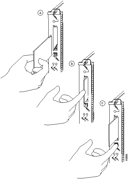
![]()
Router#
format slot0:
All sectors will be erased, proceed? [confirm]
Enter volume id (up to 30 characters):
MyNewCard
Formatting sector 1
Format device slot0 completed
Router#
Router#
config terminal
Router(config)#
no boot system
Router(config)#
boot system flash slot0:new.image
Router(config)#
config-register 0x2102
Crtl-z
Router#
copy running-config startup-config
Router#
reload
Router>
en
Password:
Router#
copy tftp:new.image slot0:new.image
20575008 bytes available on device slot0, proceed? [confirm]
Address or name of remote host [1.1.1.1]?
Loading new.image from 1.1.1.1 (via Ethernet1/0): !!!!!!!!!!!!!!!!!!!!!!!!!!!!!!
!!!!!!!!!!!!!!!!!!!!!!!!!!!!!!!!!!!!!!!!!!!!!!!!!!!!!!!!!!!!!!!!!!!!!!!!!!!!!!!!
!!!!!!!!!!!!!!!!!!!!!!!!!!!!!!!!!!!!!!!!!!!!!!!!!!!!!!!!!!!!!!!!!!!!!!!!!!!!!!!!
!!!!!!!!!!!!!!!!!!!!!!!!!!!!!!!!!!!!!!!!!!!!!!!!!!!!!!!!!!!!!!!!!!!!!!!!!!!!!!!!
!!!!!!!!!!!!!!!!!!!!!!!!!!!!!!!!!!!!!!!!!!!!!!!!!!!!!!!!!!!!!!!!!!!!!!!!!!!!!!!!
!!!!!!!!!!!!!!!!!!!!!!!!!!!!!!!!!!!!!!!!!!!!!!!!!!!!!!!!!!!!!!!!!!!!!!!!!!!!!!!!
!!!!!!!!!!!!!!!!!!!!!!!!!!!!!!!!!!!!!!!!!!!!!!!!!!!!!!!!!!!!!!!!!!!!!!!!!!!!!!!!
!!!!!!!!!!!!!!!!!!!!!!!!!!!!!!!!!!!!!!!!!!!!!!!!!!!!!!!!!!!!!!!!!!!!!!!!!!!!!!!!
!!!!!!!!!!!!!!!!!!!!!!!!!!!!!!!!!!!!!!!!!!!!!!!!!!!!!!!!!!!!!!!!!!!!!!!!!!!!!!!!