|
|
Cisco 7000 and Cisco 7507 Air Filter and Chassis Blower Replacement Instructions
Product Numbers: MAS-7KFAN and ACS-7KFILTER
This document contains instructions for replacing the air filter and the chassis blower in the Cisco 7000 and Cisco 7507.
The air filter, which is integrated with the top front chassis panel, should be kept clean by periodic vacuuming, and should be replaced if it becomes torn, worn, or dirty. You can access the filter while the system is operating by removing the bottom front chassis panel. The blower, which is located in the front interior of the chassis, need only be replaced if the existing blower fails. You must turn all system power off and remove the top and bottom front chassis panels to access the blower.
The sections in this document include the following:
This section provides brief physical and functional descriptions of the chassis blower and air filter. shows the front of the chassis with the top and bottom front panels removed to show the internal components.Internal Chassis Front View
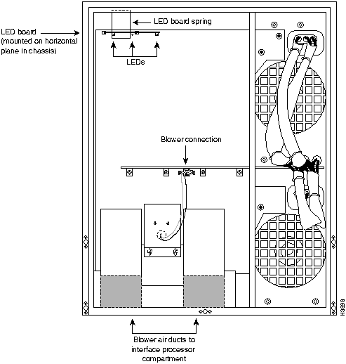
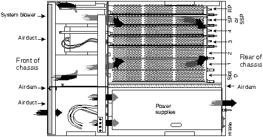
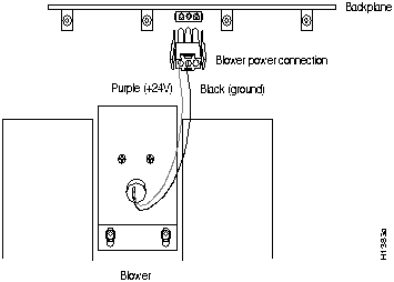
The system blower provides cooling air for the chassis internal components. The blower is located on the bottom left of the chassis interior when viewed in the orientation shown in . The blower draws air in through the air filter (which is not shown in ) and directs it up through the floor of the internal card cage and over the processor modules. The exhaust air is forced out the rear of the chassis above and to each side of the internal slot compartment. The airflow path is shown in Figure 1. The air dam shown in Figure 1 keeps the chassis blower air separate from the air drawn in by the power supply fans. A cable (purple +24V wire and black ground wire) with a keyed three-prong plug connects the blower to the backplane power bus to deliver power from the power supplies. (See the blower power connection in .)
Two air ducts on the rear of the blower, shown shaded in Figure 1, fit snugly into the two cutouts in the backplane. The blower is secured to the backplane with three large captive Phillips or Allen-head screws. (The earliest chassis manufactured use Phillips screws; the rest now use Allen-head screws.)
Figure 1 Internal Air Flow, Top-Down View of Chassis
![]()
The air filter fits into the lower frame of the top front chassis panel. (See Figure 2.) Maintaining a consistent air filter cleaning schedule helps to maintain normal system operation. A dirty filter can prohibit the flow of cooling air into the chassis and may cause an overtemperature condition.
Figure 2 Chassis Air Filter and Top Front Panel
Before you begin this installation, review the safety guidelines in this section to avoid injuring yourself or damaging the equipment.
![]()
Waarschuwing Dit waarschuwingssymbool betekent gevaar. U verkeert in een situatie die lichamelijk letsel kan veroorzaken. Voordat u aan enige apparatuur gaat werken, dient u zich bewust te zijn van de bij elektrische schakelingen betrokken risico's en dient u op de hoogte te zijn van standaard maatregelen om ongelukken te voorkomen.
Varoitus Tämä varoitusmerkki merkitsee vaaraa. Olet tilanteessa, joka voi johtaa ruumiinvammaan. Ennen kuin työskentelet minkään laitteiston parissa, ota selvää sähkökytkentöihin liittyvistä vaaroista ja tavanomaisista onnettomuuksien ehkäisykeinoista.
Attention Ce symbole d'avertissement indique un danger. Vous vous trouvez dans une situation pouvant causer des blessures ou des dommages corporels. Avant de travailler sur un équipement, soyez conscient des dangers posés par les circuits électriques et familiarisez-vous avec les procédures couramment utilisées pour éviter les accidents.
Warnung Dieses Warnsymbol bedeutet Gefahr. Sie befinden sich in einer Situation, die zu einer Körperverletzung führen könnte. Bevor Sie mit der Arbeit an irgendeinem Gerät beginnen, seien Sie sich der mit elektrischen Stromkreisen verbundenen Gefahren und der Standardpraktiken zur Vermeidung von Unfällen bewußt.
Avvertenza Questo simbolo di avvertenza indica un pericolo. La situazione potrebbe causare infortuni alle persone. Prima di lavorare su qualsiasi apparecchiatura, occorre conoscere i pericoli relativi ai circuiti elettrici ed essere al corrente delle pratiche standard per la prevenzione di incidenti.
Advarsel Dette varselsymbolet betyr fare. Du befinner deg i en situasjon som kan føre til personskade. Før du utfører arbeid på utstyr, må du vare oppmerksom på de faremomentene som elektriske kretser innebærer, samt gjøre deg kjent med vanlig praksis når det gjelder å unngå ulykker.
Aviso Este símbolo de aviso indica perigo. Encontra-se numa situação que lhe poderá causar danos físicos. Antes de começar a trabalhar com qualquer equipamento, familiarize-se com os perigos relacionados com circuitos eléctricos, e com quaisquer práticas comuns que possam prevenir possíveis acidentes.
¡Advertencia! Este símbolo de aviso significa peligro. Existe riesgo para su integridad física. Antes de manipular cualquier equipo, considerar los riesgos que entraña la corriente eléctrica y familiarizarse con los procedimientos estándar de prevención de accidentes.
Varning! Denna varningssymbol signalerar fara. Du befinner dig i en situation som kan leda till personskada. Innan du utför arbete på någon utrustning måste du vara medveten om farorna med elkretsar och känna till vanligt förfarande för att förebygga skador.
The following guidelines will help to ensure your safety and protect the equipment. This list is not inclusive of all potentially hazardous situations, so be alert.
In addition, use the following guidelines when working with any equipment that is connected to telephone wiring or other network cabling.
![]()
![]()
You need the following tools to clean or replace the air filter, and to replace the blower:
To access the air filter, you must remove the bottom front chassis panel. To access the chassis interior to replace the blower, you must remove the top and bottom front chassis panels. Carefully follow the instructions for removing and replacing the top front panel because you can damage or destroy the LED board or top front panel by forcing a misaligned panel onto or off of the chassis body.
![]()
![]()
![]()
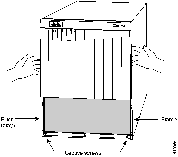
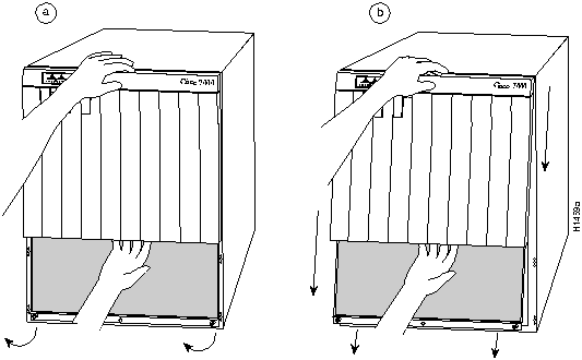
You must remove the bottom front panel before you can remove the top front panel. The plastic bottom front panel is attached to the chassis with ball studs. The top front panel is attached to the chassis with two captive screws. The EMI shielding around the outer edge of the top front panel acts as a spring and compresses when you push the panel into the chassis to keep the panel fitted tightly into the chassis opening. To remove the front panels, perform the following steps:
Figure 3 Removing the Bottom Front Panel
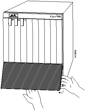
Figure 4 Removing the Top Front Panel
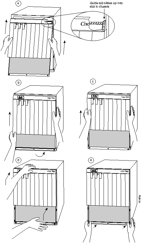
To replace the front panels, perform the following steps:
This completes the chassis front panel removal and replacement procedures.
Figure 5 Replacing the Top Front Panel
The air filter removes dust from the air drawn in by the blower. The edges of the air filter fit into the lower frame of the top front chassis panel. (See Figure 2.) Remove and vacuum the air filter at least once every two weeks (more often in unusually dusty environments). You can also wash the filter in running water, but ensure that it is completely dry before replacing it in the chassis.
Have spares on hand in case the filter tears or becomes worn, or if you have to remove and wash it. A dirty filter could restrict the flow of cooling air into the chassis and could cause an overtemperature condition. You need only remove the bottom front chassis panel to access the filter.
![]()
To clean or replace the filter, do the following:
![]()
![]()
The blower is located at the bottom of the chassis interior. (See .) Two air ducts on the rear of the blower, shown shaded in the illustration, fit snugly into the two cutouts in the backplane. The blower is secured to the backplane with three large captive screws, which are shown in Figure 6. The captive screws on most blowers are 3-mm center-hex Allen-head screws, but the earliest chassis shipped used Phillips-head screws. A 3-mm T-handle driver with a long (9-inch) handle is shipped with the spare blower.
Although the far left captive screw on the blower is slightly obscured from view by the left lip of the chassis and the left blower air duct, an access hole in the lip of the chassis provides access to this screw. By inserting the T-handle driver (or screwdriver) straight into the access hole, you should be able to find the screw without any trouble. However, if you do have trouble finding the screw, and if the lighting around the chassis is poor, you may need a flashlight to locate the screw and position the driver correctly.
![]()
![]()
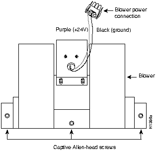
Remove the existing chassis blower as follows:
Figure 7 Blower Power Connector
![]()
Install the new chassis blower as follows:
![]()
Perform the following steps to verify that the new blower is installed correctly.
![]()
This completes the blower replacement.
Following are translations of the safety warnings that appear throughout this publication:
![]()
Waarschuwing Tijdens onweer dat gepaard gaat met bliksem, dient u niet aan het systeem te werken of kabels aan te sluiten of te ontkoppelen.
Varoitus Älä työskentele järjestelmän parissa äläkä yhdistä tai irrota kaapeleita ukkosilmalla.
Attention Ne pas travailler sur le système ni brancher ou débrancher les câbles pendant un orage.
Warnung Arbeiten Sie nicht am System und schließen Sie keine Kabel an bzw. trennen Sie keine ab, wenn es gewittert.
Avvertenza Non lavorare sul sistema o collegare oppure scollegare i cavi durante un temporale con fulmini.
Advarsel Utfør aldri arbeid på systemet, eller koble kabler til eller fra systemet når det tordner eller lyner.
Aviso Não trabalhe no sistema ou ligue e desligue cabos durante períodos de mau tempo (trovoada).
¡Advertencia! No operar el sistema ni conectar o desconectar cables durante el transcurso de descargas eléctricas en la atmósfera.
Varning! Vid åska skall du aldrig utföra arbete på systemet eller ansluta eller koppla loss kablar.
![]()
Waarschuwing Voordat u het frame opent, dient u de verbinding met het telefoonnetwerk te verbreken door de kabels te ontkoppelen om zo contact met telefoonnetwerk-spanningen te vermijden.
Varoitus Vältä joutumista kosketuksiin puhelinverkostojännitteiden kanssa irrottamalla puhelinverkoston kaapelit ennen asennuspohjan aukaisemista.
Attention Avant d'ouvrir le châssis, débrancher les câbles du réseau téléphonique afin d'éviter tout contact avec les tensions d'alimentation du réseau téléphonique.
Warnung Bevor Sie das Chassis öffnen, ziehen Sie die Telefonnetzkabel aus der Verbindung, um Kontakt mit Telefonnetzspannungen zu vermeiden.
Avvertenza Prima di aprire il telaio, scollegare i cavi della rete telefonica per evitare di entrare in contatto con la tensione di rete.
Advarsel Før kabinettet åpnes, skal kablene for telenettet kobles fra for å unngå å komme i kontakt med spenningen i telenettet.
Aviso Antes de abrir o chassis, desligue os cabos da rede telefónica para evitar contacto com a tensão da respectiva rede.
¡Advertencia! Antes de abrir el chasis, desconectar el cableado dirigido a la red telefónica para evitar contacto con voltajes de la propia red.
Varning! Koppla loss ledningarna till telefonnätet innan du öppnar chassit så att kontakten med telefonnätsspänningen bryts.
![]()
Waarschuwing Voordat u aan een frame of in de nabijheid van voedingen werkt, dient u bij wisselstroom toestellen de stekker van het netsnoer uit het stopcontact te halen; voor gelijkstroom toestellen dient u de stroom uit te schakelen bij de stroomverbreker.
Varoitus Kytke irti vaihtovirtalaitteiden virtajohto ja katkaise tasavirtalaitteiden virta suojakytkimellä, ennen kuin teet mitään asennuspohjalle tai työskentelet virtalähteiden läheisyydessä.
Attention Avant de travailler sur un châssis ou à proximité d'une alimentation électrique, débrancher le cordon d'alimentation des unités en courant alternatif ; couper l'alimentation des unités en courant continu au niveau du disjoncteur.
Warnung Bevor Sie an einem Chassis oder in der Nähe von Netzgeräten arbeiten, ziehen Sie bei Wechselstromeinheiten das Netzkabel ab bzw. schalten Sie bei Gleichstromeinheiten den Strom am Unterbrecher ab.
Avvertenza Prima di lavorare su un telaio o intorno ad alimentatori, scollegare il cavo di alimentazione sulle unità CA; scollegare l'alimentazione all'interruttore automatico sulle unità CC.
Advarsel Før det utføres arbeid på kabinettet eller det arbeides i nærheten av str¿mforsyningsenheter, skal str¿mledningen trekkes ut pOE vekselstrømsenheter og strømmen kobles fra ved strømbryteren på likestrømsenheter.
Aviso Antes de trabalhar num chassis, ou antes de trabalhar perto de unidades de fornecimento de energia, desligue o cabo de alimentação nas unidades de corrente alternada; desligue a corrente no disjuntor nas unidades de corrente contínua.
¡Advertencia! Antes de manipular el chasis de un equipo o trabajar cerca de una fuente de alimentación, desenchufar el cable de alimentación en los equipos de corriente alterna (CA); cortar la alimentación desde el interruptor automático en los equipos de corriente continua (CC).
Varning! Innan du arbetar med ett chassi eller nära strömförsörjningsenheter skall du för växelströmsenheter dra ur nätsladden och för likströmsenheter bryta strömmen vid överspänningsskyddet.
![]()
Waarschuwing Dit toestel kan meer dan één netsnoer hebben. Om het risico van een elektrische schok te verminderen, dient u de stekkers van de twee netsnoeren uit het stopcontact te halen voordat u het toestel een servicebeurt geeft.
Varoitus Tässä laitteessa saattaa olla useampi kuin yksi virtajohto. Irrota molemmat virtalähteestä tulevat johtimet ennen laitteen huoltamista, jotta vältät sähköiskun vaaran.
Attention Il est possible que cette unité soit munie de plusieurs cordons d'alimentation. Pour éviter les risques d'électrocution, débrancher les deux cordons d'alimentation avant de réparer l'unité.
Warnung Diese Einheit hat möglicherweise mehr als ein Netzkabel. Zur Verringerung der Stromschlaggefahr trennen Sie beide Netzgerätekabel ab, bevor Sie die Einheit warten.
Avvertenza Questa unità potrebbe essere dotata di più di un cavo di alimentazione. Per ridurre il rischio di scossa elettrica, scollegare i due cavi di alimentazione prima di procedere alla manutenzione dell'unità.
Advarsel Denne enheten kan være utstyrt med mer enn én strømledning. Koble fra de to strømledningene før det utføres reparasjonsarbeid på enheten for å redusere faren for elektriske støt.
Aviso Esta unidade poderá ter mais do que um cabo de alimentação. Para reduzir o risco de choque eléctrico, desligue os dois cabos de alimentação antes de efectuar reparações na unidade.
¡Advertencia! Puede ser que este equipo posea más de un cable de alimentación. Para reducir el riesgo de descarga eléctrica, desenchufar los dos cables antes de proceder al mantenimiento de la unidad.
Varning! Denna enhet kan vara försedd med mer än en nätsladd. För att minska risken för elektriska stötar skall båda nätsladdarna dras ur innan du utför underhållsarbete på enheten.
![]()
Waarschuwing Voordat u een van de onderstaande procedures uitvoert, dient u te controleren of de stroom naar het gelijkstroom circuit uitgeschakeld is. Om u ervan te verzekeren dat alle stroom UIT is geschakeld, kiest u op het schakelbord de stroomverbreker die het gelijkstroom circuit bedient, draait de stroomverbreker naar de UIT positie en plakt de schakelaarhendel van de stroomverbreker met plakband in de UIT positie vast.
Varoitus Varmista, että tasavirtapiirissä ei ole virtaa ennen seuraavien toimenpiteiden suorittamista. Varmistaaksesi, että virta on KATKAISTU täysin, paikanna tasavirrasta huolehtivassa kojetaulussa sijaitseva suojakytkin, käännä suojakytkin KATKAISTU-asentoon ja teippaa suojakytkimen varsi niin, että se pysyy KATKAISTU-asennossa.
Attention Avant de pratiquer l'une quelconque des procédures ci-dessous, vérifier que le circuit en courant continu n'est plus sous tension. Pour en être sûr, localiser le disjoncteur situé sur le panneau de service du circuit en courant continu, placer le disjoncteur en position fermée (OFF) et, à l'aide d'un ruban adhésif, bloquer la poignée du disjoncteur en position OFF.
Warnung Vor Ausführung der folgenden Vorgänge ist sicherzustellen, daß die Gleichstromschaltung keinen Strom erhält. Um sicherzustellen, daß sämtlicher Strom abgestellt ist, machen Sie auf der Schalttafel den Unterbrecher für die Gleichstromschaltung ausfindig, stellen Sie den Unterbrecher auf AUS, und kleben Sie den Schaltergriff des Unterbrechers mit Klebeband in der AUS-Stellung fest.
Avvertenza Prima di svolgere una qualsiasi delle procedure seguenti, verificare che il circuito CC non sia alimentato. Per verificare che tutta l'alimentazione sia scollegata (OFF), individuare l'interruttore automatico sul quadro strumenti che alimenta il circuito CC, mettere l'interruttore in posizione OFF e fissarlo con nastro adesivo in tale posizione.
Advarsel Før noen av disse prosedyrene utføres, kontroller at strømmen er frakoblet likestrømkretsen. Sørg for at all strøm er slått AV. Dette gjøres ved å lokalisere strømbryteren på brytertavlen som betjener likestrømkretsen, slå strømbryteren AV og teipe bryterhåndtaket på strømbryteren i AV-stilling.
Aviso Antes de executar um dos seguintes procedimentos, certifique-se que desligou a fonte de alimentação de energia do circuito de corrente contínua. Para se assegurar que toda a corrente foi DESLIGADA, localize o disjuntor no painel que serve o circuito de corrente contínua e coloque-o na posição OFF (Desligado), segurando nessa posição a manivela do interruptor do disjuntor com fita isoladora.
¡Advertencia! Antes de proceder con los siguientes pasos, comprobar que la alimentación del circuito de corriente continua (CC) esté cortada (OFF). Para asegurarse de que toda la alimentación esté cortada (OFF), localizar el interruptor automático en el panel que alimenta al circuito de corriente continua, cambiar el interruptor automático a la posición de Apagado (OFF), y sujetar con cinta la palanca del interruptor automático en posición de Apagado (OFF).
Varning! Innan du utför någon av följande procedurer måste du kontrollera att strömförsörjningen till likströmskretsen är bruten. Kontrollera att all strömförsörjning är BRUTEN genom att slå AV det överspänningsskydd som skyddar likströmskretsen och tejpa fast överspänningsskyddets omkopplare i FRÅN-läget.
![]()
Waarschuwing Nadat de bedrading van de gelijkstroom voeding aangebracht is, verwijdert u het plakband van de schakelaarhendel van de stroomverbreker en schakelt de stroom weer in door de hendel van de stroomverbreker naar de AAN positie te draaien.
Varoitus Yhdistettyäsi tasavirtalähteen johdon avulla poista teippi suojakytkimen varresta ja kytke virta uudestaan kääntämällä suojakytkimen varsi KYTKETTY-asentoon.
Attention Une fois l'alimentation connectée, retirer le ruban adhésif servant à bloquer la poignée du disjoncteur et rétablir l'alimentation en plaçant cette poignée en position de marche (ON).
Warnung Nach Verdrahtung des Gleichstrom-Netzgeräts entfernen Sie das Klebeband vom Schaltergriff des Unterbrechers und schalten den Strom erneut ein, indem Sie den Griff des Unterbrechers auf EIN stellen.
Avvertenza Dopo aver eseguito il cablaggio dell'alimentatore CC, togliere il nastro adesivo dall'interruttore automatico e ristabilire l'alimentazione spostando all'interruttore automatico in posizione ON.
Advarsel Etter at likestrømsenheten er tilkoblet, fjernes teipen fra håndtaket på strømbryteren, og deretter aktiveres strømmen ved å dreie håndtaket på strømbryteren til PÅ-stilling.
Aviso Depois de ligar o sistema de fornecimento de corrente contínua, retire a fita isoladora da manivela do disjuntor, e volte a ligar a corrente ao deslocar a manivela para a posição ON (Ligado).
¡Advertencia! Después de cablear la fuente de alimentación de corriente continua, retirar la cinta de la palanca del interruptor automático, y restablecer la alimentación cambiando la palanca a la posición de Encendido (ON).
Varning! När du har kopplat ledningarna till strömförsörjningsenheten för inmatad likström tar du bort tejpen från överspänningsskyddets omkopplare och slår på strömmen igen genom att ställa överspänningsskyddets omkopplare i TILL-läget.
Cisco Connection Online (CCO) is Cisco Systems' primary, real-time support channel. Maintenance customers and partners can self-register on CCO to obtain additional content and services.
Available 24 hours a day, 7 days a week, CCO provides a wealth of standard and value-added services to Cisco's customers and business partners. CCO services include product information, software updates, release notes, technical tips, the Bug Navigator, configuration notes, brochures, descriptions of service offerings, and download access to public and authorized files.
CCO serves a wide variety of users through two interfaces that are updated and enhanced simultaneously---a character-based version and a multimedia version that resides on the World Wide Web (WWW). The character-based CCO (called "CCO Classic") supports Zmodem, Kermit, Xmodem, FTP, Internet e-mail, and fax download options, and is excellent for quick access to information over lower bandwidths. The WWW version of CCO provides richly formatted documents with photographs, figures, graphics, and video, as well as hyperlinks to related information.
You can access CCO in the following ways:
http://www.cisco.com
cio.cisco.com
For a copy of CCO's Frequently Asked Questions (FAQ), contact
ciohelp@cisco.com.
For additional information, contact
cioteam@cisco.com.

tac@cisco.com.
To obtain general information about Cisco Systems, Cisco products, or upgrades, contact 800 553-6387, 408 526-7208, or
csrep@cisco.com.
|
|
Copyright 1988-1995 © Cisco Systems Inc.