|
|
PA-F-MM and PA-F-SM FDDI Port Adapter Installation and Configuration
Product Numbers: PA-F-MM(=), PA-F-SM(=), and CAB-FMDD=
This configuration note describes the installation and configuration of the PA-F-MM(=) and PA-F-SM(=) Fiber Distributed Data Interface (FDDI) port adapters, which can be used in the Cisco 7200 series routers, and on the second-generation Versatile Interface Processor (VIP2) in all Cisco 7500 series routers, and in Cisco 7000 series routers using the 7000 Series Route Switch Processor (RSP7000) and 7000 Series Chassis Interface (RSP7000CI). (Refer to the section "Software and Hardware Requirements" on page 3.)
This configuration note is organized into the following three parts.
The following sections include general reference information: "Translated Safety Warnings," on page 42, and "Cisco Connection Online" on page 44.
The Cisco Internetwork Operating System (Cisco IOS) software running the router contains extensive features and functionality. The effective use of many of many of these features is easier if you have more information at hand. For additional information on configuring the Cisco 7000 family routers and VIP2, or the Cisco 7200 series routers, the following documentation resources are available to you:
cs-rep@cisco.com
. You can also refer to the Cisco Information Packet that shipped with your router.
Port Adapter Installation Prerequisites
This section provides software requirements, a list of parts and tools you will need to perform the port adapter installation, and safety and ESD-prevention guidelines to help you avoid injury and damage to the equipment during installation. Also included is information on the systems in which port adapters can be installed and overview information on interface specifications.
The following sections discuss general information and information about port adapter installation requirements:
Software and Hardware Requirements
The FDDI port adapters require that the host Cisco 7000 family router is running Cisco IOS Release 11.1(472), or later, and that the host Cisco 7200 series router is running Cisco IOS Release 11.1(472) or later.
You need the following tools and parts to install a port adapter. If you need additional equipment, contact a service representative for ordering information.
Following are safety guidelines that you should follow when working with any equipment that connects to electrical power or telephone wiring, or that uses a laser for data transmission.
The single-mode aperture port contains an FDDI laser warning label, as shown in Figure 1.
Figure 1 : Laser Warning Labels on PA-F-SM
Electrical Equipment Guidelines
Follow these basic guidelines when working with any electrical equipment:
Use the following guidelines when working with any equipment that is connected to telephone wiring or to other network cabling:
Preventing Electrostatic Discharge Damage
Electrostatic discharge (ESD) damage, which can occur when electronic cards or components are improperly handled, results in complete or intermittent failures. Port adapters and processor modules comprise printed circuit boards that are fixed in metal carriers. Electromagnetic interference (EMI) shielding and connectors are integral components of the carrier. Although the metal carrier helps to protect the board from ESD, use a preventive antistatic strap during handling.
Following are guidelines for preventing ESD damage:
For safety, periodically check the resistance value of the antistatic strap. The measurement should be between 1 and 10 megohms.
FDDI, which specifies a 100-Mbps, wire-speed, token-passing dual-ring network using fiber-optic transmission media, is defined by the ANSI X3.1 standard and by ISO 9314, the international version of the ANSI standard. An FDDI network comprises two token-passing fiber-optic rings: a primary ring and a secondary ring.
A ring consists of two or more point-to-point connections between adjacent stations. On most networks, the primary ring is used for data communication, and the secondary ring is used as a backup. Single attachment stations attach to one ring and are typically attached through a concentrator; Class A, or dual attachment stations (DASs), attach to both rings.
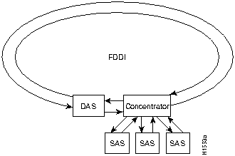
Figure 2 shows a typical FDDI configuration with both dual-attached and single-attached connections. Single attachment stations typically attach to the primary ring through a concentrator, which provides connections for multiple single-attached devices. The concentrator ensures that a failure or power down of any single attachment station does not interrupt the ring. Single attachment stations use one transmit port and one receive port to attach to the single ring. DASs (Class A) have two physical ports, designated PHY A and PHY B, each of which connects the station to both the primary and secondary rings. Each port is a receiver for one ring and a transmitter for the other. For example, PHY A receives traffic from the primary ring and PHY B transmits to it.
Figure 2 : Typical Configuration with DAS, Concentrator, and Single Attachment
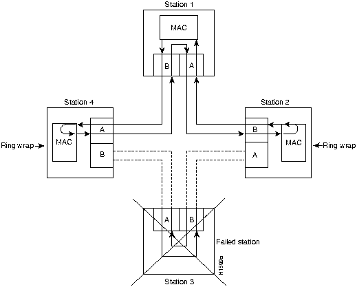
The dual rings in an FDDI network provide fault tolerance. If a station on a dual ring shuts down or fails, such as Station 3 in Figure 3, the ring automatically wraps (doubles back on itself) to form a single contiguous ring. This removes the failed station from the ring, but allows the other stations to continue operation. In Figure 3, the ring wraps to eliminate Station 3 and forms a smaller ring that includes only Stations 1, 2, and 4. A second failure could cause the ring to wrap in both directions from the point of failure, which would segment the ring into two separate rings that could not communicate with each other.
Figure 3 : DAS Station Failure and Ring Recovery Example
For example, if Station 1 in Figure 3 fails after Station 3 fails, Stations 2 and 4 will each be isolated because no path for communication exists between them. Subsequent failures cause additional segmentation.
Optical bypass switching avoids segmentation by eliminating failed stations from the ring. An optical bypass switch allows the light signal to pass directly through it, completely bypassing the failed or shut down station.
The FDDI port adapters have an optical bypass switch feature by way of a DIN connection. Optical bypass switches avoid segmentation by eliminating failed stations from the ring. During normal operation, an optical bypass switch allows the light signal to pass uninterrupted directly through itself. When a station with a bypass switch fails, the bypass switch reroutes the signal back onto the ring before it reaches the failed station, so the ring does not have to wrap back on itself.
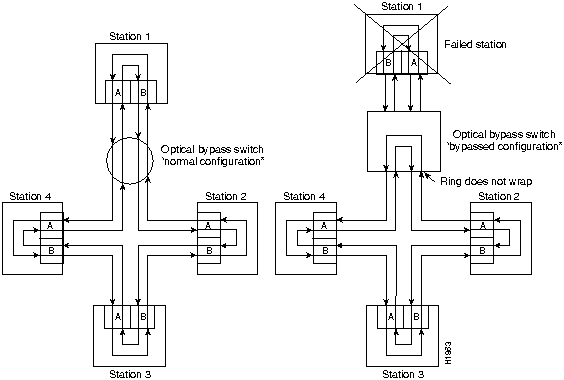
Figure 4 shows an optical bypass switch installed at Station 1. In the normal configuration shown, Station 1 is functioning normally, so the optical bypass switch appears transparent. The switch essentially allows the signals to pass through it without interruption. However, if Station 1 fails, the optical bypass switch enables the bypassed configuration shown on the right in Figure 4.
Figure 4 : Optical Bypass Operation on a DAS
The optical bypass switch reroutes the light signal by intercepting it before it reaches the failed Station 1 and sends it back out to the ring. This allows the signal to maintain its existing path and direction without wrapping back on itself. However, stations that are operating normally repeat the signal when sending it back out to the ring. Optical bypass switches do not repeat or drive the signal (they just allow the signal to pass through them), so significant signal loss can occur when the downstream neighbor (the next station on the ring) is far away.
Another technique for fault tolerance is dual homing, whereby critical devices are attached to two concentrators. Only the designated primary concentrator is active unless it (or its link) fails. If the primary does fail, the backup (passive) concentrator is automatically activated and sustains the ring.
Typically, FDDI uses two types of fiber-optic cable:
Mode refers to the angle at which light rays (signals) are reflected and propagated through the optical fiber core, which acts as a waveguide for the light signals. Multimode fiber has a relatively thick core (62.5/125-micron) that reflects light rays at many angles. Single-mode fiber has a narrow core (8.7 to 10/125-micron) that allows the light to enter only at a single angle.
Although multimode fiber allows more light signals to enter at a greater variety of angles (modes), the different angles create multiple propagation paths that cause the signals to spread out in time and limits the rate at which data can be accurately received. This distortion does not occur on the single path of the single-mode signal; therefore, single-mode fiber is capable of higher bandwidth and greater cable run distances that multimode fiber. In addition, multimode transmitters usually use LEDs as a light source, and single-mode transmitters use a laser diode, which is capable of sustaining faster data rates. Both types use a photodiode detector at the receiver to translate the light signal into electrical signals.
The FDDI standard sets total fiber lengths of 2 kilometers (1.2 miles) for multimode fiber and 15 kilometers (9.3 miles) for single-mode fiber. (The maximum circumference of the FDDI network is only half the specified distance because of signal wrapping or loopback that occurs during fault correction.) The FDDI standard allows a maximum of 500 stations with a maximum distance between active stations of 2 kilometers.
Table 1 lists the signal descriptions for the mini-DIN optical bypass switch available on the FDDI port adapters. The mini-DIN-to-DIN adapter cable (CAB-FMDD=) allows connection to an optical bypass switch with a DIN connector (which is larger than the mini-DIN connector on the FDDI port adapters).
Table 1 : Optical Bypass Switch Pinout
The FDDI port adapter implementation complies with Version 6.1 of the X3T9.5 FDDI specification, offering a Class A dual attachment interface that supports the fault-recovery methods of DAS. The FDDI port adapter supports dual homing and optical bypass and complies with ANSI X3.1 and ISO 9314 FDDI standards.
Maximum Transmission Distances for FDDI Connections
The maximum transmission distances for single-mode and multimode FDDI stations are shown in Table 2. If the distance between two connected stations is greater than the maximum distance shown, significant signal loss can result.
Table 2 : FDDI Maximum Transmission Distances
FDDI Port Adapter Optical Power Parameters
The multimode and single-mode optical-fiber connections conform to the following optical power parameters:
What is the FDDI Port Adapter?
The FDDI port adapters provide an interface for both single-mode and multimode fiber-optic cable. The two physical ports (PHY A and PHY B) are available with either single-mode (SC) or multimode MIC receptacles. Each port adapter's FDDI connection allows a maximum bandwidth of 100 Mbps per the FDDI standard.
The following FDDI port adapter combinations are available:
Figure 5 : FDDI Port Adapter PA-F-MM, Faceplate View
Figure 6 : FDDI Port Adapter PA-F-SM, Faceplate View
The FDDI port adapters can be installed on the VIP2 in port adapter slot 0 and port adapter slot 1, or in the Cisco 7200 series routers in any of the chassis' port adapter slots: 1 through 6 for the Cisco 7206. Port adapters have a handle attached, but this handle is occasionally not shown to allow a full view of detail on the port adapter's faceplate.
The following sections discuss information specific to the FDDI port adapter:
Port Adapter Locations on the VIP2 and in the Cisco 7200 Series Router
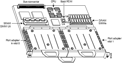
Figure 7 shows a VIP2 with installed port adapters. With the VIP2 oriented as shown in Figure 7, the left port adapter is in port adapter slot 0, and the right port adapter is in port adapter slot 1. Port adapters have handles that allow for easy installation and removal; however, they are occasionally not shown in this publication to highlight port adapter faceplate detail. In the Cisco 7000, Cisco 7507, and Cisco 7513 chassis the VIP2 is installed vertically. In the Cisco 7010 and Cisco 7505 chassis the VIP2 is installed horizontally.
Figure 7 : Port Adapters on the VIP2 (Horizontal Orientation Shown)
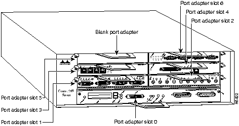
Figure 8 shows a Cisco 7206 with port adapters installed. In the Cisco 7206, port adapter slot 1 is in the lower left position and port adapter slot 6 is in the upper right position.
Figure 8 : Port Adapters in the Cisco 7206
The FDDI port adapter contains the enabled LED, standard on all port adapters, and status LEDs for each port. After system initialization, the enabled LED goes on to indicate that the FDDI port adapter has been enabled for operation. (The LEDs are shown in Figure 9.)
The following conditions must be met before the enabled LED goes on:
If any of these conditions is not met, or if the initialization fails for other reasons, the enabled LED does not go on. In addition to the enabled LED, the FDDI port adapter has the following three LEDs:
Figure 9 : LEDs on the FDDI Port Adapter, Partial PA-F-SM Faceplate Shown
The states of the port adapter's LED combinations, and the meanings of each are described in Table 3.
Table 3 : FDDI Port Adapter LED States, Refer to Figure 9
FDDI Port Adapter Fiber-Optic Cables
The interface receptacles on the FDDI port adapter are MICs for multimode and SC-type connectors for simplex and duplex, single-mode applications. The multimode receptacle is an FDDI-standard physical sublayer (PHY) connector that encodes and decodes the data into a format acceptable for fiber transmission. The multimode receptacle accepts standard 62.5/125-micron, multimode fiber-optic cable using the MIC and, with proper cable terminators, can accept 50/125 micron fiber-optic cable. Fiber-optic cables are commercially available and are not available from Cisco Systems. Multimode uses the integrated MIC shown in Figure 10, at both the port adapter end and the network end.
Figure 10 : Multimode FDDI Network Interface MIC
For FDDI single-mode connections, use one duplex SC connector (see Figure 11) or two single SC connectors, at both the port adapter end and the network end. (See Figure 12.) Single-mode optical fiber cable has a narrow core (8.7 to 10/125-micron), which allows the light to enter only at a single angle.
Figure 11 : Duplex SC Connector
Figure 12 : Simplex SC Connector
VIP2 and the FDDI Port Adapter
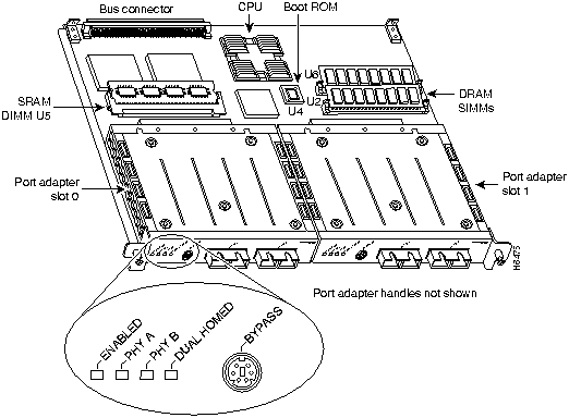
The FDDI port adapter is used on the VIP2, and can be installed in either port adapter slot 0 or port adapter slot 1. There are two FDDI port adapters: PA-F-MM and PA-F-SM. PA-F-MM uses multimode MIC optical-fiber interface connections and PA-F-SM uses single-mode SC-type optical-fiber interface connections. Both PA-F-MM and PA-F-SM have optical bypass switching capability in the form of a mini-DIN connector. Figure 13 shows PA-F-SM installed on a VIP2 in port adapter slots 0 and 1. Port adapters have a handle attached, but this handle is not shown to allow a full view of detail on each port adapter's faceplate.
Figure 13 : VIP2 with PA-F-SM Port Adapters in Port Adapter Slots 0 and 1
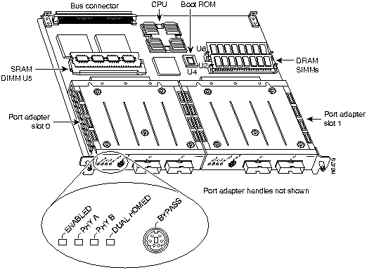
Figure 14 shows PA-F-MM installed on a VIP2 in port adapter slots 0 and 1.
Figure 14 : VIP2 with PA-F-MM Port Adapters in Port Adapter Slots 0 and 1
The following sections include information specific to the FDDI port adapter and its use on the VIP2 in Cisco 7000 family routers:
Installing or Replacing a Port Adapter on a VIP2
Depending on the circumstances you might need to install a new port adapter on a VIP2 motherboard or replace a failed port adapter in the field. In either case, you need a number 1 Phillips screwdriver, an antistatic mat onto which you can place the removed interface processor, and an antistatic container into which you can place a failed port adapter for shipment back to the factory.
When only one port adapter is installed on a VIP2, a blank port adapter must fill the empty slot to allow the VIP2 and router chassis to conform to electromagnetic interference (EMI) emissions requirements, and so that air flows through the chassis properly. If you plan to install a new port adapter, you must first remove the blank port adapter.
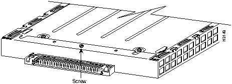
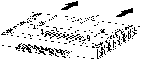
Following is the standard procedure for removing and replacing any type of port adapter on the VIP2:
Figure 15 : Location of Port Adapter Screw, Partial Port Adapter View
Figure 16 : Pulling a Port Adapter Out of a Slot, Partial Port Adapter View
Figure 17 : Removing a Port Adapter
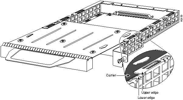
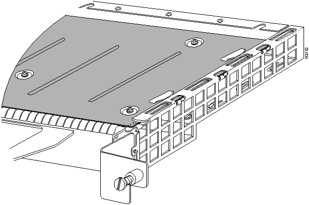
Figure 18 : Aligning the Carrier Edge with Upper and Lower Slot Edges, Partial View
This completes the procedure for installing a new port adapter or replacing a port adapter on a VIP2.
Attaching FDDI Port Adapter Cables
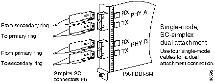
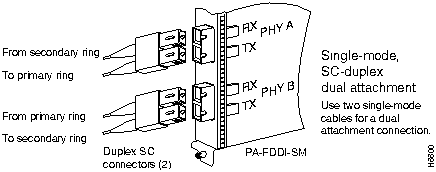
Both single-mode and multimode, dual attachment connections are available. Fiber-optic cable connects directly to the FDDI ports. Single-mode uses simplex or duplex SC-type transmit and receive cables.
Connect single-mode, dual attachment as shown in Figure 19 or Figure 20.
Figure 19 : Single-Mode Dual Attachment with Four Simplex SC-Simplex Cables
Figure 20 : Single-Mode Dual Attachment with Two Duplex SC-Duplex Cables
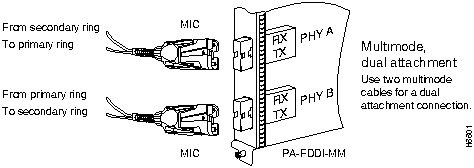
Multimode uses MIC cables. Connect multimode, dual attachment as shown in Figure 21
Figure 21 : Multimode Dual Attachment with MIC Cables
Attaching an Optical Bypass Switch
An optical bypass switch is a device installed between the ring and the station that provides additional fault tolerance to the network. If an FDDI port adapter that is connected to a bypass switch fails or shuts down, the bypass switch activates automatically and allows the light signal to pass directly through it, bypassing the port adapter completely.
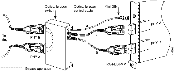
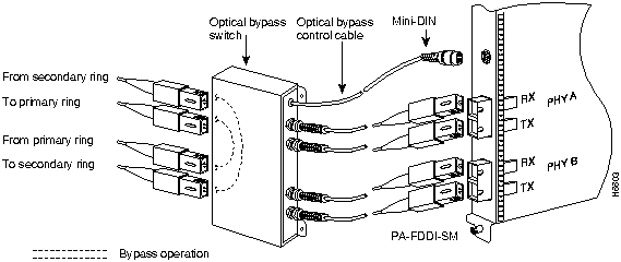
Following are general instructions for connecting an optical bypass switch to the FDDI port adapter; however, your particular bypass switch may require a different connection scheme. Use these steps and the illustrations in Figure 22 and Figure 23, on page page 23, as general guidelines, but for specific connection requirements, refer to the instructions provided by the manufacturer of the optical bypass switch.
A port for connecting an optical bypass switch is provided on the multimode/multimode port adapter (PA-F-MM shown in Figure 22), and the single-mode/single-mode port adapter (PA-F-SM, shown in Figure 23).
Figure 22 : Optical Bypass Switch Connection (PA-F-MM)
Figure 23 : Optical Bypass Switch Connection (PA-F-SM)
Configuring the FDDI Port Adapter Interfaces
If you installed a new FDDI port adapter or if you want to change the configuration of an existing interface, you must enter Configuration mode using the configure command. If you replaced an FDDI port adapter that was previously configured, the system will recognize the new FDDI interfaces and bring them up in their existing configuration. After you verify that the new FDDI port adapter is installed correctly (the enabled LED goes on), use the privileged-level configure command to configure the new interfaces. Be prepared with the information you will need, such as the following:
The configure command requires privileged-level access to the EXEC command interpreter, which usually requires a password. Contact your system administrator if necessary to obtain EXEC-level access. For a summary of the configuration options available and instructions for configuring the FDDI interfaces on the VIP2, refer to the appropriate configuration publications listed in the section "If You Need More Information" on page 2.
Selecting Chassis Slot, Port Adapter, and FDDI Port Numbers
The following section describes how to identify chassis slot, port adapter, and FDDI port numbers.
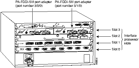
In the router, physical port addresses specify the actual physical location of each interface port on the router interface processor end. (See Figure 24.) This address is composed of a three-part number in the format chassis slot number/port adapter number/interface port number, as follows:
The first number identifies the chassis slot in which the VIP2 is installed (as shown in the example system in Figure 24).
The second number identifies the physical port adapter slot number on the VIP2, and is either 0 or 1.
The third number identifies the interface port on each FDDI port adapter, which is always numbered as interface 0.
Interface ports on the VIP2 maintain the same address regardless of whether other interface processors are installed or removed. However, when you move a VIP2 to a different slot, the first number in the address changes to reflect the new chassis slot number.
Figure 24 shows some of the slot port adapter and interface ports of a sample Cisco 7505 system. For example, on a VIP2 equipped with two FDDI port adapters in slot 3, the address of the first FDDI port adapter is 3/0/0 (chassis slot 3, port adapter slot 0, and interface port 0) and address of the second FDDI port adapter is 3/1/0.
The first port adapter slot number is always 0. The second port adapter slot number is always 1. The individual interface port numbers always begin with 0. The number of additional ports depends on the number of ports on a port adapter.
Figure 24 : Interface Port Number Example (Cisco 7505 Shown)
You can identify interface ports by physically checking the slot/port adapter/interface port location on the back of the router or by using software commands to display information about a specific interface or all interfaces in the router.
The following steps describe a basic configuration. Press the Return key after each step unless otherwise noted. At any time you can exit the privileged level and return to the user level by entering disable at the prompt as follows:
Following is a basic configuration procedure:
To check the interface configuration using the show and ping commands, proceed to the section "Checking the Configuration."
After configuring the new interface, use the show commands to display the status of the new interface or all interfaces and the ping command to check connectivity.
Using show Commands to Verify the VIP2 Status
The following steps use show commands to verify that the new interfaces are configured and operating correctly.
If the interface is down and you configured it as up, or if the displays indicate that the hardware is not functioning properly, ensure that the network interface is properly connected and terminated. If you still have problems bringing the interface up, contact a service representative for assistance.
Using show Commands to Display Interface Information To display information about a specific interface, use the show interfaces command with the interface type and port address in the format show interfaces [type slot/port adapter/port].
Following is an example of how the show interfaces [type slot/port adapter/port] command displays status information (including the physical slot and port address) for the interfaces you specify. In these examples, most of the status information for each interface is omitted. The following example of the show interfaces fddi slot/port adapter/port command shows all of the information specific to the first FDDI port (interface port 0) in chassis slot 3, port adapter slot 0:
Interfaces are administratively shut down until you enable them. With the show interfaces command, use just the argument type to display information about a specific type of interface only. For example, show interfaces fddi will display information about just the FDDI ports in the system.
The show version (or show hardware) command displays the configuration of the system hardware (the number of each interface processor type installed), the software version, the names and sources of configuration files, and the boot images. Following is an example of the show version command used with a Cisco 7500 series system in which an FDDI-equipped VIP2 is installed:
To determine which type of port adapter is installed on a VIP2 in your system, use the show diag slot command. Specific port adapter information is displayed, as shown in the following examples of PA-F-SM and PA-F-MM port adapters in chassis slots 3 and 5:
(Where Part number in the last line refers to a PA-F-SM port adapter.)
(Where Part number in the last line refers to a PA-F-MM.)
Using the ping Command The packet internet groper (ping) command allows you to verify that an interface port is functioning properly and to check the path between a specific port and connected devices at various locations on the network. This section provides brief descriptions of the ping command. After you verify that the system and VIP2 have booted successfully and are operational, you can use this command to verify the status of interface ports.
The ping command sends an echo request out to a remote device at an IP address that you specify. After sending a series of signals, the command waits a specified time for the remote device to echo the signals. Each returned signal is displayed as an exclamation point (!) on the console terminal; each signal that is not returned before the specified time-out is displayed as a period (.). A series of exclamation points (!!!!!) indicates a good connection; a series of periods (.....) or the messages [timed out] or [failed] indicate that the connection failed.
Following is an example of a successful ping command to a remote server with the address 1.1.1.10:
For complete descriptions of interface subcommands and the configuration options available for VIP2-related interfaces, and which support VIP2 functionality, refer to the publications listed in the section "If You Need More Information" on page 2.
Cisco 7200 Series and the FDDI Port Adapter
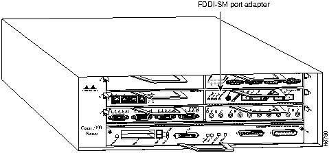
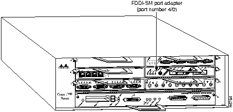
The FDDI port adapter is used in the Cisco 7200 series routers and can be installed in any of the available port adapter slots. Figure 25 shows a Cisco 7206 with an FDDI-SM port adapter installed in port adapter slot 4.
Figure 25 : Cisco 7206 with a FDDI-SM in Port Adapter Slot 4
The following sections discuss information that is specific to the FDDI port adapter and its use in the Cisco 7200 series routers:
Installing or Replacing a Port Adapter in the Cisco 7200 Series
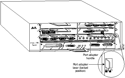
Depending on your circumstances, you might need to install a new port adapter in a Cisco 7200 series router or replace a failed port adapter in the field. In either case no tools are necessary; all port adapters available for the Cisco 7200 series connect directly to the router midplane and are locked into position by a port adapter lever. When removing and replacing a port adapter, you will need an antistatic mat onto which you can place a removed port adapter and an antistatic container into which you can place a failed port adapter for shipment back to the factory.
When a port adapter slot is not in use, a blank port adapter must fill the empty slot to allow the router to conform to EMI emissions requirements and to allow proper air flow across the port adapters. If you plan to install a new port adapter in a slot that is not in use, you must first remove a blank port adapter.
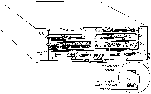
Following is the procedure for removing a port adapter from a Cisco 7200 series router:
Figure 26 : Placing the Port Adapter Lever in the Unlocked Position (Cisco 7206 shown)
Figure 27 : Handling a Port Adapter
This completes the procedure for removing a port adapter from a Cisco 7200 series router.
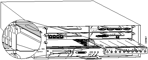
Following is the procedure for installing a new port adapter in a Cisco 7200 series router:
Figure 28 : Aligning the Port Adapter Metal Carrier Between the Slot Guides (Cisco 7206 shown)
Figure 29 : Placing the Port Adapter Lever in the Locked Position (Cisco 7206 shown)
This completes the procedure for installing a new port adapter in a Cisco 7200 series router.
Attaching FDDI Port Adapter Interface Cables
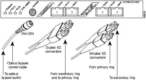
Both single-mode and multimode, dual attachment connections are available. Fiber-optic cable connects directly to the FDDI ports. Single-mode uses simplex or duplex SC-type transmit and receive cables. Connect single-mode, dual attachment as shown in Figure 30.
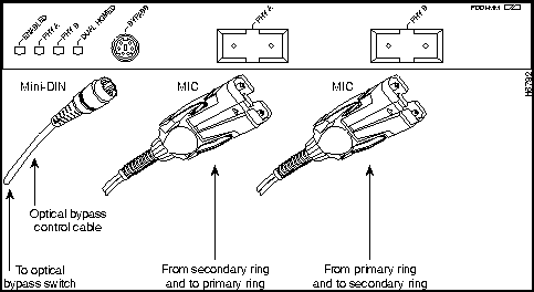
Multimode uses MIC cables. Connect multimode, dual attachment as shown in Figure 31.
Figure 31 : Multimode Dual Attachment with MIC Cables and Optical Bypass Control Cable
Attaching an Optical Bypass Switch
An optical bypass switch is a device installed between the ring and the station that provides additional fault tolerance to the network. If an FDDI port adapter that is connected to a bypass switch fails or shuts down, the bypass switch activates automatically and allows the light signal to pass directly through it, bypassing the port adapter completely.
For general instructions for connecting an optical bypass switch to the FDDI port adapter, refer to the section "Attaching an Optical Bypass Switch" on page 22.
Configuring the FDDI Port Adapter Interfaces
If you installed a new FDDI port adapter or if you want to change the configuration of an existing interface, you must enter Configuration mode using the configure command. If you replaced an FDDI port adapter that was previously configured, the system will recognize the new FDDI interfaces and bring them up in their existing configuration. After you verify that the new FDDI port adapter is installed correctly (the enabled LED goes on), use the privileged-level configure command to configure the new interfaces. Be prepared with the information you will need, such as the following:
The configure command requires privileged-level access to the EXEC command interpreter, which usually requires a password. Contact your system administrator if necessary to obtain EXEC-level access. For a summary of the configuration options available and instructions for configuring the FDDI interfaces on the VIP2, refer to the appropriate configuration publications listed in the section "If You Need More Information" on page 2.
Selecting Chassis Slot, Port Adapter, and FDDI Port Numbers
The following section describes how to identify port adapter slot and FDDI interface port numbers.
In the router, physical port addresses specify the actual physical location of each interface port on the router. (See Figure 32.) This address is composed of a two-part number in the format port adapter slot number/interface port number, as follows:
Interface ports maintain the same address regardless of whether other port adapters are installed or removed from the slot. However, when you move a port adapter to a different slot, the first number in the address changes to reflect the new chassis slot number.
Figure 32 shows some of the slot port adapter and interface ports of a Cisco 7206. The port adapter slot numbers start with 1 and continue through 6 (slot 0 is always reserved for the Fast Ethernet port on the I/O controller---if present). The individual interface port numbers always begin with 0. The number of additional ports depends on the number of ports on a port adapter.
For example, the FDDI port adapter in port adapter slot 4 would have the addresses 4/0. (Refer Figure 32.) If the FDDI port adapter was in port adapter slot 1, these same interface port would be numbered 1/0. Port adapters can occupy any port adapter slot. There are no restrictions.
Figure 32 : FDDI Interface Port Number Example
You can identify interface ports by physically checking the slot/interface port location on the front of the router or by using show commands to display information about a specific interface or all interfaces in the router.
The following steps describe a basic interface configuration. Press the Return key after each step unless otherwise noted. At any time you can exit the privileged level and return to the user level by entering disable at the prompt as follows:
Following is an example of a basic configuration procedure:
To check the interface configuration using show commands, proceed to the section "Checking the Configuration."
After configuring the new interface, use the show commands to display the status of the new interface or all interfaces and use the ping command to check connectivity.
Using show Commands to Verify the New Interface Status
The following steps use show commands to verify that the new interfaces are configured and operating correctly.
If the interface is down and you configured it as up, or if the displays indicate that the hardware is not functioning properly, ensure that the network interface is properly connected and terminated. If you still have problems bringing the interface up, contact a service representative for assistance.
Using show Commands to Display Interface Information
To display information about a specific interface, use the show interfaces command with the interface type and port address in the format show interfaces [type slot/port].
Following is an example of how the show interfaces [type slot/port] command displays status information (including the physical slot and port address) for the interfaces you specify. In these examples, most of the status information for each interface is omitted. The following example of the show interfaces fddi type slot/port command shows all of the information specific to the FDDI port (interface port 0) in port adapter slot 4:
Interfaces are administratively shut down until you enable them. With the show interfaces type slot/port command, use arguments such as the interface type (fddi, and so forth), slot, and the port number (slot/port) to display information about a specific FDDI interface only.
The show version (or show hardware) command displays the configuration of the system hardware (the number of each port adapter type installed), the software version, the names and sources of configuration files, and the boot images. Following is an example of the show version command:
To determine which type of port adapter is installed in your system, use the show diag slot command. Specific port adapter information is displayed, as shown in the following example of an FDDI port adapter in port adapter slot 4:
For command descriptions and examples for the Cisco 7200 series routers, refer to the publications listed in the section "If You Need More Information" on page 2.
Using the ping Command
The packet internet groper (ping) command allows you to verify that an interface port is functioning properly and to check the path between a specific port and connected devices at various locations on the network. This section provides brief descriptions of the ping command. After you verify that the system has booted successfully and is operational, you can use this command to verify the status of interface ports. Refer to the publications listed in the section "If You Need More Information" on page 2 for detailed command descriptions and examples.
The ping command sends an echo request out to a remote device at an IP address that you specify. After sending a series of signals, the command waits a specified time for the remote device to echo the signals. Each returned signal is displayed as an exclamation point (!) on the console terminal; each signal that is not returned before the specified time-out is displayed as a period (.). A series of exclamation points (!!!!!) indicates a good connection; a series of periods (.....) or the messages [timed out] or [failed] indicate that the connection failed.
Following is an example of a successful ping command to a remote server with the address 1.1.1.10:
For complete descriptions of interface subcommands and the configuration options available for Cisco 7200 series-related interfaces, refer to the publications listed in the section "If You Need More Information" on page 2.
Following is an example of the laser warning labels that appears on the product:
Waarschuwing Wanneer geen kabel aangesloten is, kan er onzichtbare laserstraling geëmitteerd worden uit de apertuurpoorten van de enkelvoudige-modus FDDI-kaart ("Fiber Distributed Data Interface" = "Interface van door glasvezels gedistribueerde gegevens"). Vermijd blootstelling en staar niet in de open aperturen.
Varoitus Yksitoimintoisen FDDI-kortin avoimista porteista saattaa vapautua näkymättömiä lasersäteitä kaapelin ollessa irrotettuna. Vältä säteilyä ja avoimiin aukkoihin katsomista.
Attention Des rayons laser invisibles peuvent s'échapper des ouvertures prévues pour la carte d'interface des données distribuées par fibres optiques monomode (Fiber Distributed Data Interface ou FDDI) quand un câble n'est pas connecté. Eviter toute exposition et ne pas approcher les yeux des ouvertures.
Warnung Wenn kein Kabel angeschlossen ist, wird möglicherweise unsichtbare Laserstrahlung von den Steckanschlüssen der Monomode-FDDI-Karte (Glasfaserdatenübertragungs-Schnittstelle; Fiber Distributed Data Interface) ausgestrahlt. Schützen Sie sich vor Strahlung, und blicken Sie nicht direkt in offene Steckanschlüsse.
Avvertenza Radiazioni laser invisibili potrebbero essere emesse dalle porte di apertura della scheda FDDI (Fiber Distributed Data Interface - Interfaccia di dati distribuiti a fibre) a modo singolo quando il cavo non è stato collegato. Evitare l'esposizione a tali radiazioni e non fissare alcuna porta aperta.
Advarsel Usynlig laserstråling kan emitteres fra åpningsutgangene på FDDI-kort med kabel av monomodusfiber når de ikke er tilkoblet en ledning. Unngå utsettelse for stråling, og stirr ikke inn i åpne åpninger.
Aviso Radiação laser invisível poderá ser emitida através das portas de abertura da placa FDDI (Interface de Dados Distribuídos por Fibra Óptica) de modo simples, mesmo quando não houver nenhum cabo ligado. Evite exposição e não espreite por estas aberturas.
¡Atención! La tarjeta FDDI modo sencillo puede emitir radiaciones láser invisibles por los orificios de los puertos cuando no se haya conectado ningún cable. Evitar la exposición y no mirar fijamente los orificios abiertos.
Varning! Osynlig laserstrålning kan avges från portöppningarna för FDDI-kortet för enkelmodsfiber när ingen kabel är ansluten (FDDI: Fiber Distributed Data Interface = gränssnitt för dataöverföring med fiberoptik). Utsätt dig inte för denna strålning och titta inte in i öppningarna.
Waarschuwing Klasse-1 laser produkt.
Varoitus Luokan 1 lasertuote.
Attention Produit laser de classe 1.
Warnung Laserprodukt der Klasse 1.
Avvertenza Prodotto laser di Classe 1.
Advarsel Laserprodukt av klasse 1.
Aviso Produto laser de classe 1.
¡Atención! Producto láser Clase I.
Varning! Laserprodukt av klass 1.
Cisco Connection Online (CCO), formerly Cisco Information Online (CIO), is Cisco Systems' primary, real-time support channel. Maintenance customers and partners can self-register on CCO to obtain additional content and services.
Available 24 hours a day, 7 days a week, CCO provides a wealth of standard and value-added services to Cisco's customers and business partners. CCO services include product information, software updates, release notes, technical tips, the Bug Navigator, configuration notes, brochures, descriptions of service offerings, and download access to public and authorized files.
CCO serves a wide variety of users through two interfaces that are updated and enhanced simultaneously---a character-based version and a multimedia version that resides on the World Wide Web (WWW). The character-based CCO supports Zmodem, Kermit, Xmodem, FTP, Internet e-mail, and fax download options, and is excellent for quick access to information over lower bandwidths. The WWW version of CCO provides richly formatted documents with photographs, figures, graphics, and video, as well as hyperlinks to related information.
You can access CCO in the following ways:
For a copy of CCO's Frequently Asked Questions (FAQ), contact
Copyright 1988-1996 © Cisco Systems Inc.
![]()

![]()
![]()
![]()
Pin
Direction
Description
1
Out
+5V to secondary switch
2
Out
+5V to primary switch
3
Out
Enable optical bypass switch primary
4
Out
Enable optical bypass switch secondary
5
In
Sense optical bypass switch---1 kohm to +5 V
6
Out
Ground---Sense optical bypass switch return
Transceiver Type
Maximum Distance Between Stations
Single-mode
Up to 9.3 miles (up to 15 km)
Multimode
Up to 1.2 miles (up to 2 km)


![]()

PA-F-MM and PA-F-SM LEDs1
Indication
PHY A
PHY B
Dual-Homed
---
---
---
Not connected
---
---
O
Not possible
---
O
---
Wrap B
---
O
O
Dual homed (B connected to M port)
O
---
---
Wrap A
O
---
O
Dual homing back-up (A connected to M port; B port is not connected
O
O
---
Thru A
O
O
O
Not possible
1 For the LED patterns "" means off, "O" means on. Refer to Figure9.


![]()
![]()
![]()
![]()
![]()
Router# disable
Router>
Router#
configure terminal
Enter configuration commands, one per line. End with CNTL/Z.
Router(config)#
Router(config)#
interface fddi 1/0/0
Router(config-int)#
ip address 1.1.1.10 255.255.255.0
Router(config-int)#
no shutdown
Router#
copy running-config startup-config
[OK]
Router#
Router# show int f 3/0/0
Fddi3/0/0 is up, line protocol is up
  Hardware is cxBus FDDI, address is 0000.0c0c.4444 (bia 0060.3e47.4360)
  Internet address is 14.0.0.2/8
  MTU 4470 bytes, BW 100000 Kbit, DLY 100 usec, rely 255/255, load 10/255
  Encapsulation SNAP, loopback not set, keepalive not set
  ARP type: SNAP, ARP Timeout 04:00:00
  Phy-A state is connect, neighbor is Unknown, status QLS
  Phy-B state is active, neighbor is A, status SILS
  ECM is in, CFM is c_wrap_b, RMT is ring_op,
  Requested token rotation 5000 usec, negotiated 0 usec
  Configured tvx is 2500 usec
  LER for PortA = 09, LER for PortB = 0C ring operational 11:36:23
  Upstream neighbor 0000.0c0c.8888, downstream neighbor 0000.0c0c.8888
  Last input 00:02:22, output 00:00:06, output hang never
  Last clearing of "show interface" counters 14:57:58
  Output queue 0/40, 0 drops; input queue 0/75, 0 drops
  5 minute input rate 3922000 bits/sec, 147 packets/sec
  5 minute output rate 3962000 bits/sec, 148 packets/sec
     7523044 packets input, 631964210 bytes, 0 no buffer
     Received 0 broadcasts, 0 runts, 0 giants
     0 input errors, 0 CRC, 0 frame, 0 overrun, 0 ignored, 0 abort
     7523554 packets output, 625092443 bytes, 0 underruns
     0 output errors, 0 collisions, 1 interface resets
     0 output buffer failures, 0 output buffers swapped out
     0 transitions, 0 traces,  0 claims, 0 beacon
Router# show version
Cisco Internetwork Operating System Software
IOS (tm) GS Software (RSP-JV-M), Released Version 11.1(472) [biff 101]
Copyright (c) 1986-1996 by cisco Systems, Inc.
Compiled Fri 10-May-96 16:20 by biff
Image text-base: 0x600108A0, data-base: 0x608DC000

ROM: System Bootstrap, Version 5.3(18168) [biff 61], INTERIM SOFTWARE
ROM: GS Software (RSP-BOOT-M), Experimental Version 11.1(472) [biff 103]

Router uptime is 20 hours, 34 minutes
System restarted by power-on
System image file is "slot0:zippy/biff/rsp-jv-mz.111.472", booted via slot0

cisco RSP2 (R4600) processor with 16384K bytes of memory.
R4600 processor, Implementation 32, Revision 2.0
Last reset from power-on
G.703/E1 software, Version 1.0.
SuperLAT software copyright 1990 by Meridian Technology Corp).
Bridging software.
X.25 software, Version 2.0, NET2, BFE and GOSIP compliant.
TN3270 Emulation software (copyright 1994 by TGV Inc).
Primary Rate ISDN software, Version 1.0.
Chassis Interface.
2 VIP2 controllers (8 Ethernet)(2 Fddi).
8 Ethernet/IEEE 802.3 interfaces.
2 FDDI network interfaces.
125K bytes of non-volatile configuration memory.

8192K bytes of Flash PCMCIA card at slot 0 (Sector size 128K).
8192K bytes of Flash internal SIMM (Sector size 256K).
No slave installed in slot 6.
Configuration register is 0x0
Router# show diag 3
Slot 3:
        Physical slot 3, ~physical slot 0xC, logical slot 3, CBus 0
        Microcode Status 0xC
        Master Enable, LED, WCS Loaded
        Board is analyzed
        Pending I/O Status: Console I/O
        EEPROM format version 1
        VIP2 controller, HW rev 2.2, board revision UNKNOWN
        Serial number: 03507946  Part number: 73-1684-02
        Test history: 0x00        RMA number: 00-00-00
        Flags: cisco 7000 board; 7500 compatible

        EEPROM contents (hex):
          0x20: 01 15 02 02 00 35 86 EA 49 06 94 02 00 00 00 00
          0x30: 12 2B 00 2A 1A 00 00 00 00 00 00 00 00 00 00 00

        Slot database information:
        Flags: 0x4      Insertion time: 0x1988 (20:32:53 ago)

        Controller Memory Size: 8 MBytes

        PA Bay 0 Information:
                FDDI PA, 1 ports
                EEPROM format version 1
                HW rev 1.0, Board revision 21
                Serial number: 03524551  Part number: 73-1630-01
Router# show diag 5
Slot 5:
        Physical slot 5, ~physical slot 0xA, logical slot 5, CBus 0
        Microcode Status 0x4
        Master Enable, LED, WCS Loaded
        Board is analyzed
        Pending I/O Status: None
        EEPROM format version 1
        VIP2 controller, HW rev 2.2, board revision UNKNOWN
        Serial number: 03507948  Part number: 73-1684-02
        Test history: 0x00        RMA number: 00-00-00
        Flags: cisco 7000 board; 7500 compatible

        EEPROM contents (hex):
          0x20: 01 15 02 02 00 35 86 EC 49 06 94 02 00 00 00 00
          0x30: 12 2B 00 2A 1A 00 00 00 00 00 00 00 00 00 00 00

        Slot database information:
        Flags: 0x4      Insertion time: 0x3C3C (20:32:59 ago)

        Controller Memory Size: 8 MBytes

        PA Bay 0 Information:
                FDDI PA, 1 ports
                EEPROM format version 1
                HW rev 1.0, Board revision 21
                Serial number: 02825768 Part number: 73-1558-01
Router# ping 1.1.1.10 <Return>
Type escape sequence to abort.
Sending 5, 100-byte ICMP Echoes to 1.1.1.10, timeout is 2 seconds:
!!!!!
Success rate is 100 percent (5/5), round-trip min/avg/max = 1/15/64 ms
Router#

If the connection fails, verify that you have the correct IP address for the server and that the server is active
(powered on), and repeat the ping command.
![]()

![]()
Router# disable
Router>
Router#
configure terminal
Enter configuration commands, one per line. End with CNTL/Z.
Router(config)#
Router(config)#
interface fddi 4/0
Router(config-int)#
ip address 1.1.1.10 255.255.255.0
Router(config-int)#
no shutdown
Router#
copy running-config startup-config
[OK]
Router#
Router# show int f 4/0
Fddi4/0 is up, line protocol is up
  Hardware is MIF68840_MM, address is 1.1.1.10 (bia 0000.0000.0000)
  Internet address is 1.1.1.10
  MTU 4470 bytes, BW 100000 Kbit, DLY 100 usec, rely 255/255, load 10/255
  Encapsulation SNAP, loopback not set, keepalive not set
  ARP type: SNAP, ARP Timeout 04:00:00
  Phy-A state is connect, neighbor is Unknown, status Q
  Phy-B state is active, neighbor is A, status H
  ECM is in, CFM is c_wrap_b, RMT is ring_op,
  Requested token rotation 5000 usec, negotiated 0 usec
  Configured tvx is 2500 usec
  LER for PortA = 09, LER for PortB = 0C ring operational 11:36:23
  Upstream neighbor 0000.0c0c.8888, downstream neighbor 0000.0c0c.8888
  Last input 00:02:22, output 00:00:06, output hang never
  Last clearing of "show interface" counters 14:57:58
  Output queue 0/40, 0 drops; input queue 0/75, 0 drops
  5 minute input rate 3922000 bits/sec, 147 packets/sec
  5 minute output rate 3962000 bits/sec, 148 packets/sec
     7523044 packets input, 631964210 bytes, 0 no buffer
     Received 0 broadcasts, 0 runts, 0 giants
     0 input errors, 0 CRC, 0 frame, 0 overrun, 0 ignored, 0 abort
     7523554 packets output, 625092443 bytes, 0 underruns
     0 output errors, 0 collisions, 1 interface resets
     0 output buffer failures, 0 output buffers swapped out
     0 transitions, 0 traces,  0 claims, 0 beacon
Router# show version

Cisco Internetwork Operating System Software
IOS (tm) 7200 Software (C7200-J-M), Version 11.1(472) [biff 105]
Copyright (c) 1986-1996 by cisco Systems, Inc.
Compiled Sun 21-Apr-95 12:22 by
Image text-base: 0x600088A0, data-base: 0x605A4000

ROM: System Bootstrap, Version 11.1(10979) RELEASED SOFTWARE

Router uptime is 8 hours, 22 minutes
System restarted by reload
System image file is "slot0:c7200-j-mz.960421", booted via slot0

cisco 7200 (R4700) processor with 22528K/10240K bytes of memory.
R4700 processor, Implementation 33, Revision 1.0 (Level 2 Cache)
Last reset from power-on
Bridging software.
X.25 software, Version 2.0, NET2, BFE and GOSIP compliant.
Chassis Interface.
4 Ethernet/IEEE 802.3 interfaces.
4 FDDI network interfaces.
125K bytes of non-volatile configuration memory.

20480K bytes of Flash PCMCIA card at slot 0 (Sector size 128K).
4096K bytes of Flash internal SIMM (Sector size 256K).
Configuration register is 0x2
Router# show diag 4

Slot 4:
FDDI DAS (Multimode) port adapter, 1 port
Port adapter is analyzed
Port adapter insertion time 1d19h ago
Hardware revision 1.0           Board revision UNKNOWN
Serial number     1329897       Part number    73-1558-01
Test history      0x0           RMA number     00-00-00
EEPROM format version 1
EEPROM contents (hex):
  0x20: 01 0A 01 00 00 14 4A E9 49 06 16 01 00 00 00 00
  0x30: 07 1C 00 00 00 00 00 00 00 00 00 00 00 00 00 00
Router# ping 1.1.1.10 <Return>
Type escape sequence to abort.
Sending 5, 100-byte ICMP Echoes to 1.1.1.10, timeout is 2 seconds:
!!!!!
Success rate is 100 percent (5/5), round-trip min/avg/max = 1/15/64 ms
Router#

If the connection fails, verify that you have the correct IP address for the server and that the server is active
(powered on), and repeat the ping command.

![]()
http://www.cisco.com.
cco.cisco.com.
ccohelp@cisco.com.
For additional information, contact
ccoteam@cisco.com.
tac@cisco.com.
To obtain general information about Cisco Systems, Cisco products, or upgrades, contact 800 553-6387, 408 526-7208, or
csrep@cisco.com.

![]()
![]()
![]()
![]()
![]()
![]()
![]()
![]()