|
|
This chapter provides physical and functional overviews of the Cisco 7206 router. It contains physical descriptions of the router hardware and major components, and functional descriptions of hardware-related features. Descriptions and examples of software commands are included only when they are necessary for replacing, installing, configuring, or maintaining the router hardware.
The Cisco 7206 is part of the Cisco 7200 series routers. The six-slot Cisco 7206 supports multiprotocol, multimedia routing and bridging with a wide variety of protocols and any combination of Ethernet, Fast Ethernet, Token Ring, Fiber Distributed Data Interface (FDDI), and serial media.
Network interfaces reside on port adapters that provide the connection between the router's three Peripheral Component Interconnect (PCI) buses and external networks. The Cisco 7206 has six slots (slot 1 through slot 6) for the port adapters, one slot for an Input/Output (I/O) controller, and one slot for a network processing engine. You can place the port adapters in any of the six available slots.
There are bays for up to two AC-input or DC-input power supplies. The Cisco 7206 will operate with one power supply. While a second power supply is not required, it allows load sharing and increased system availability. The Cisco 7206 does not support a mixture of AC- and DC-input power.
The Cisco 7206 provides the following features:
The front of the Cisco 7206 provides access to an I/O controller and up to six network interface port adapters (see Figure 1-1). The I/O controller contains the following: a local console port for connecting a data terminal (or data terminal equipment [DTE]) and an auxiliary port for connecting a modem (or other data communications equipment [DCE]) or other devices for configuring and managing the router; two Personal Computer Memory Card International Association (PCMCIA) slots for Flash memory cards; an optional Fast Ethernet port. The Fast Ethernet port provides a 100-Mbps connection to the network.
Figure 1-1 : Cisco 7206 Router---Front View
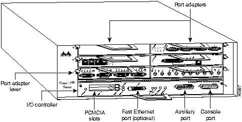
The port adapters installed in the Cisco 7206 are of the same type as those installed on the second-generation Versatile Interface Processors (VIP2s) in the Cisco 7000 family routers. The port adapters installed in the Cisco 7206 support OIR. For an explanation of OIR, refer to the section "Online Insertion and Removal" later in this chapter.
Port adapter slots in the Cisco 7206 router are numbered from left to right, beginning with port adapter slot 1 and continuing through port adapter slot 6. Port adapter slot 0 is the Fast Ethernet port on the I/O controller (refer to Figure 1-2).
Figure 1-2 : Port Adapter Slot Numbering
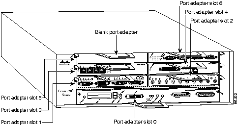
The rear of the Cisco 7206 router provides access to the network processing engine and up to two power supplies (refer to Figure 1-3).
Figure 1-3 : Cisco 7206 Router---Rear View
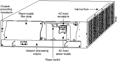
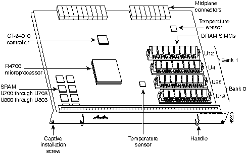
The 150-megahertz (MHz) network processing engine has no external connectors or LEDs. There are two handles for removing and installing the network processing engine and two captive installation screws for securing it to the chassis.
The Cisco 7206 router comes equipped with one 280W AC-input or one 280W DC-input power supply. A fully configured Cisco 7206 router operates with only one installed power supply; however, a second, optional power supply provides hot-swappable, load-sharing, redundant power. Figure 1-3 shows the rear of a Cisco 7206 router configured with a single AC-input power supply. (A power supply filler plate is installed over the second power supply bay.)
The power supply has the router's main power switch and either an AC-input power receptacle or a hardwired DC-input power cable (depending on the type of installed power supply). Adjacent to the power supply bays there is a 10 x 32-inch chassis ground receptacle that provides a chassis ground connection for ESD equipment or a grounding wire (refer to Figure 1-3).
Three internal fans draw cooling air into chassis and across internal components to maintain an acceptable operating temperature. (Refer to Figure 1-3.) The three fans are enclosed in a tray that is located in the subchassis.
The I/O controller, port adapters, power supplies, and network processing engine slide into their respective chassis slots and connect directly to the router's midplane; there are no internal cables to connect. The midplane distributes DC power from the power supplies to the I/O controller, port adapters, fan tray, and network processing engine.
The midplane also identifies OIR of the port adapters, bridges the PCI buses from the port adapters to packet static random-access memory (SRAM) on the network processing engine, arbitrates traffic across the PCI buses, and generates the clock signals for the port adapters on each PCI bus.
The Cisco 7206 operates as either a tabletop or rack-mounted unit. A rack-mount kit is standard equipment included with all Cisco 7206 routers when they are shipped from the factory. The kit provides the hardware needed to mount the router in a standard 19-inch equipment rack or a Telco rack. Steps for installing the Cisco 7206 router in an equipment rack are explained in the chapter "Installing the Cisco 7206." If you are not rack-mounting your Cisco 7206, place it on a sturdy tabletop or platform.
A fully configured Cisco 7206, with two installed power supplies and all chassis slots filled, weighs approximately 50 pounds (22.7 kilograms [kg]). For clearance requirements and rack-mount installation considerations, refer to the section "Site Environment" in the chapter "Preparing for Installation."
Table 1-1 lists the Cisco 7206 router physical specifications and power requirements.
Table 1-1 : Cisco 7206 Physical Specifications
The Cisco 7206 router is easy to service; all its major components are field replaceable units (FRUs). The following Cisco 7206 components are FRUs:
The following sections provide brief overviews of each FRU. Instructions for removing and replacing FRUs are contained in separate documents called configuration notes. For example, If you need to replace the fan tray in your Cisco 7206 router, refer to the configuration note Cisco 7206 Subchassis and Fan Tray Replacement Instructions (Document Number 78-3228-xx). This configuration note accompanies every subchassis and fan tray shipped from the factory as a FRU. The configuration note is also available on the Cisco Connection Documentation, Enterprise Series CD, and on Cisco Connection Online (CCO), previously called Cisco Information Online (CIO).
For ordering information, contact a customer service representative.
The network processing engine maintains and executes the system management functions for the Cisco 7206 router. The network processing engine also shares the system memory and environmental monitoring functions with the I/O controller.
The network processing engine consists of the following components (refer to Figure 1-4):
The network processing engine performs the following system management functions:
Figure 1-4 : Cisco 7206 Network Processing Engine
Table 1-2 lists the network processing engine memory components.
Table 1-2 : Network Processing Engine Memory Components
Table 1-3 lists the network processing engine factory-installed DRAM configurations and their product numbers.
Table 1-3 : DRAM SIMM Configurations
The Input/Output controller shares the system memory functions and the environmental monitoring functions for the Cisco 7206 router with the network processing engine.
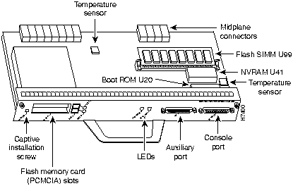
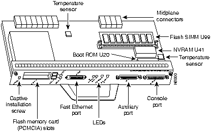
The I/O controller is available with an optional Fast Ethernet port. Figure 1-5 shows an I/O controller without the Fast Ethernet port. Figure 1-6 shows an I/O controller with the Fast Ethernet port. The I/O controller consists of the following components:
Figure 1-5 : I/O Controller---Without Fast Ethernet Port
Figure 1-6 : I/O Controller---With Fast Ethernet Port
Table 1-4 lists the I/O controller memory components.
Table 1-4 : I/O Controller Memory Components
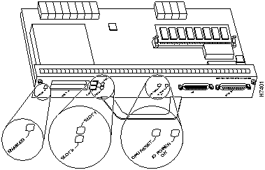
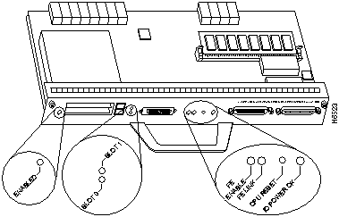
Depending on whether the Fast Ethernet port is present, either two or four LEDs on the I/O controller faceplate indicate system status; two additional LEDs indicate the status of the Flash memory cards installed in either PCMCIA slot.
Figure 1-7 shows the LEDs of an I/O controller that does not have the Fast Ethernet port. Figure 1-8 shows the LEDs of an I/O controller that has the Fast Ethernet port. Table 1-5 lists I/O controller LEDs and their functions. To use the LEDs for troubleshooting the I/O controller, refer to the section "Identifying Startup Problems" in the chapter "Troubleshooting the Installation."
Next to the IO power OK LED on the I/O controller faceplate is the CPU reset button. The CPU reset button resets the entire system.
Figure 1-7 : I/O Controller LEDs and CPU Reset Button---Without Fast Ethernet Port
Figure 1-8 : I/O Controller LEDs and CPU Reset Button---With Fast Ethernet Port
Table 1-5 : I/O Controller LEDs
The Cisco 7206 is shipped from the factory with up to six installed port adapters that provide a variety of network media types (based on your order). The port adapters connect directly to the router's midplane. Port adapters installed in the Cisco 7206 router support OIR.
For a description of OIR, refer to the section "Online Insertion and Removal" later in this chapter. For general instructions about how to remove and replace a port adapter, refer to the section "Replacing a Port Adapter" in the chapter "Maintaining the Cisco 7206."
The Cisco 7206 comes equipped with one 280W AC-input power supply or one 280W DC-input power supply. You must order the second power supply separately.
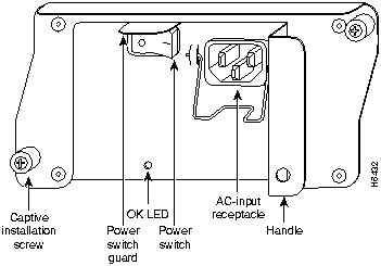
A handle on the AC and DC power supplies provide a grip point for removing and replacing the power supply. (Figure 1-9 shows the faceplate of the AC-input power supply.) Two captive installation screws secure the power supply to the chassis and seat the power supply in the router midplane. A Power OK LED indicates that the power supply is delivering +5 VDC to the router midplane.
The AC-input power supply has a receptacle for an AC-input power cable. A modular power cable connects the AC-input power supply to the site AC power source. A cable-retention clip secures the power cable to the AC-input power supply. The DC-input power supply has a DC-input power cable hardwired to a DC power receptacle.
Table 1-1 lists the AC-input and DC-input power supply system power specifications, including input voltage and operating frequency ranges.
Figure 1-9 : Cisco 7206 AC-Input Power Supply
The power supplies monitor their own temperatures and internal voltages. If either power supply detects an overvoltage or overtemperature condition, it shuts down to avoid damage to itself or other system components. For a description of power-supply shutdown conditions and thresholds, refer to the section "Environmental Monitoring and Reporting Functions" in this chapter.
The fan tray, shown in Figure 1-10, consists of three fans that are enclosed in a metal case. The fan tray is located in the subchassis and receives --12 VDC through a DC power harness that connects directly to the router midplane. You must remove the subchassis to access the fan tray.
Figure 1-10 : Cisco 7206 Fan Tray
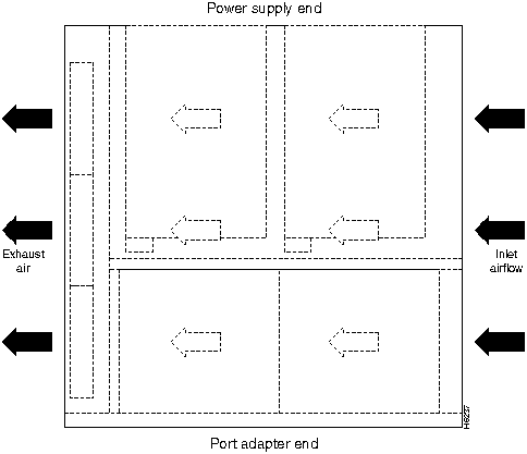
The fan tray draws cooling air in through the intake vent on the right side of the chassis (when viewing the router from the front), and moves the air across the internal components and out the exhaust vent on the left side of the chassis.
Figure 1-11 shows the air flow through the router.
Figure 1-11 : Internal Air Flow---Top View
The left and right sides of the chassis must remain unobstructed to ensure adequate air flow and prevent overheating inside the chassis; we recommend at least three inches of clearance. (See the section "Site Requirements" in the chapter "Preparing for Installation.")
Temperature sensors on the network processing engine and I/O controller monitor the internal air temperature and send warning messages when the internal air temperature approaches a specified threshold. If the internal temperature exceeds the specified threshold, the system environmental monitor shuts down all internal power to prevent equipment damage from excessive heat.
Subchassis (including the Midplane)
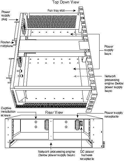
The subchassis (shown in Figure 1-12) has one slot for the network processing engine, two bays for power supplies, and one slot for the fan tray. The subchassis also houses the router midplane. To replace the router midplane, you must replace the entire subchassis.
The port adapter side of the midplane has six plugs for the port adapters and one plug for the I/O controller. The power supply side of the midplane has two plugs for power supplies, a plug for the fan tray's power harness, and one plug for the network processing engine. The midplane supplies DC power to the router's internal components.
Figure 1-12 : Cisco 7206 Subchassis---Top Down and Rear Views
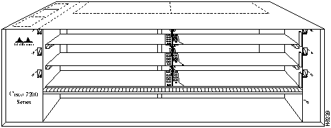
The Cisco 7206 chassis, shown in Figure 1-13, has six slots for the port adapters, one slot for the I/O controller, and one bay for the subchassis. To replace the chassis, you must remove all of the internal components, including the subchassis.
Figure 1-13 : Cisco 7206 Chassis
The Cisco 7206 supports up to two installed Intel Series 2+ Flash memory cards.
Flash memory (Flash memory cards and the Flash SIMM on the I/O controller) allows you to remotely load and store multiple system and boot helper images. You can download a new image over the network and then add the new image to Flash memory or replace existing files. You can also transfer images between Flash memory cards and the onboard Flash memory SIMM. You can then boot the router either manually or automatically from any of the stored images. Flash memory can also function as a TFTP server to allow other routers to boot remotely from stored images or copy them into their own Flash memory.
Table 1-6 lists the Flash memory card options supported by the Cisco 7206.
Table 1-6 : Flash Memory Card Options
This section provides a functional overview of the Cisco 7206. It describes the numbering and addressing of the port adapters for the router, the environmental monitoring and reporting functions, and online insertion and removal (OIR). These descriptions will help you become familiar with the capabilities of the Cisco 7206 router.
Port Adapter Slot and Logical Interface Numbering
The six port adapters in the Cisco 7206 provide the connection between the router's three Peripheral Component Interconnect (PCI) buses, called mb0, mb1, and mb2, and external networks. Bus mb0 is for the optional Fast Ethernet port on the I/O controller, bus mb1 is for port adapter slots 1, 3, and 5, and bus mb2 is for port adapter slots 2, 4, and 6.
The port adapters are categorized as high, medium, and low bandwidth. The high and medium bandwidth port adapters should be evenly distributed between bus mb1 and bus mb2. Information on port adapter categories and bus configurations is contained in the configuration note Cisco 7206 Port Adapter Hardware Configuration Guidelines (Document Number 78-3471-xx). This configuration note accompanies every Cisco 7206 router that is shipped from the factory. This configuration note is also available on the Cisco Connection Documentation, Enterprise Series CD, and on Cisco Connection Online (CCO).
In the Cisco 7206, the port adapter slot number is the chassis slot in which a port adapter is installed, while the logical interface number is the physical location of the interface port on a port adapter. Port adapter slots are numbered from 1 through 6; port adaptor slot 0 is the Fast Ethernet port on the I/O controller. (Refer to Figure 1-2 for the numbering scheme of the port adapter slots.) The number of logical interfaces depends on the type of port adapter.
The Media Access Control (MAC)-layer or hardware address is a standardized data link layer address that is required for certain network interface types. These addresses are not used by other devices in the network; they are specific and unique to each port. The Cisco 7206 uses a specific method to assign and control the MAC-layer addresses of its port adapters. For a description of the MAC-layer address, refer to the section "MAC-Layer Address" later in this chapter.
Port adapter slots maintain the same slot number regardless of whether other port adapters are installed or removed. However, when you move a port adapter to a different slot, the port adapter's logical interface number changes to reflect the new slot number.
You can identify port adapter slots by using software commands to display information about a specific port adapter or for all port adapters in the Cisco 7206. To display information about all port adapter slots, use the show interfaces command. To display information about a specific port adapter slot, use the show interfaces command with the port adapter type and slot number in the format show interfaces (port adapter type and slot number/port number). If you abbreviate the command (sho int) and do not specify port adapter type and slot number (or arguments), the system interprets the command as show interfaces and displays the status of all port adapters and ports.
Following is an example of how the show interfaces command, used without arguments, displays status information (including the physical port adapter number) for each port adapter in the Cisco 7206. In the following example, most of the status information for each interface is omitted.
You can also use arguments such as the interface type (Ethernet, TokenRing, Fddi, and so forth) and the port address (slot/port) to display information about a specific interface only.
The following example shows the display for the first port on the Token Ring port adapter in port adapter slot 3:
For complete descriptions and instructions of the commands used to configure your Cisco 7206, refer to the Configuration Fundamentals Configuration Guide and Configuration Fundamentals Command Reference publications, which are available on the Cisco Connection Documentation, Enterprise Series CD, or in print.
All local-area network (LAN) interfaces (ports) require unique MAC-layer addresses, also known as hardware addresses. Typically, the MAC address of an interface is stored on a memory component that resides directly on the interface circuitry; however, the OIR feature requires a different method. For a description of OIR, refer to the section "Online Insertion and Removal" later in this chapter.
The OIR feature allows you to remove a port adapter and replace it with another identically configured one. If the new port adapter matches the port adapter you removed, the system immediately brings it on line. In order to allow OIR, an address allocator with a unique MAC addresses is stored in an EEPROM on the router midplane. Each address is reserved for a specific port and slot in the router regardless of whether a port adapter resides in that slot. The MAC addresses are assigned to the slots in sequence. The first address is assigned to slot 0, and the last address is assigned to slot 6. This address scheme allows you to remove port adapters and insert them into other routers without causing the MAC addresses to move around the network or be assigned to multiple devices.
Note that if the MAC addresses were stored on each port adapter, OIR would not function because you could never replace one port adapter with an identical one; the MAC addresses would always be different. Also, each time a port adapter was replaced, other devices on the network would have to update their data structures with the new address, and, if they did not do so quickly enough, could cause the same MAC address to appear in more than one device at the same time.
All port adapters in the Cisco 7206 support online insertion and removal (OIR).This function allows you to install and replace port adapters while the router is operating; you do not need to notify the software or shut down the system power.
The following is a functional description of OIR for background information only; for specific procedures for installing and replacing a port adapter in a Cisco 7206 router, refer to the appropriate configuration note.
Each port adapter has a bus connector that connects it to the router's midplane. Each midplane connector has a set of tiered pins in three lengths. The pins send specific signals to the system as they make contact with the port adapter. The system assesses the signals it receives and the order in which it receives them to determine if a port adapter is being removed or inserted into the midplane. From these signals, the system determines whether to reinitialize a new interface or shut down a removed interface. For example, when inserting an port adapter, the longest pins make contact with the port adapter first, and the shortest pins make contact last. The system recognizes the signals and the sequence in which it receives them.
When you remove or insert a port adapter in a Cisco 7206 router, the midplane pins send signals to notify the system, which then performs as follows:
OIR functionality allows you to add, remove, or replace port adapters while the system is on line. This provides a method that is seamless to end users on the network, maintains all routing information, and ensures session preservation.
Environmental Monitoring and Reporting Functions
Environmental monitoring and reporting functions are controlled by the network processing engine and allow you to maintain normal system operation by identifying and resolving adverse conditions prior to loss of operation. The environmental monitoring functions constantly monitor the internal chassis air temperature and DC supply voltages and currents. Each power supply monitors its own voltage and temperature and shuts itself down if it detects a critical condition within the power supply. If conditions reach shutdown thresholds, the system shuts down to avoid equipment damage from excessive heat. The reporting functions periodically log the values of measured parameters so that you can retrieve them for analysis later, and the reporting functions display warnings on the console if any of the monitored parameters exceed defined thresholds.
The environmental monitoring functions use the following levels of status conditions to monitor the system. Four sensors, two on the network processing engine and two on the I/O controller, monitor the temperature of the cooling air as it moves through the chassis. Table 1-7 lists the temperature thresholds for the processor-monitored levels.
Table 1-8 lists the DC power thresholds for the normal, warning, and critical (power-supply-monitored) levels.
Table 1-7 : Typical Processor-Monitored Temperature Thresholds
Table 1-8 : Typical Power Supply-Monitored DC-Voltage Thresholds
If the air temperature exceeds a defined threshold, the system controller displays warning messages on the console terminal and, if the temperature exceeds the shutdown threshold, it shuts down the system. The system stores the present parameter measurements for both temperature and DC voltage in NVRAM, so that you can retrieve them later as a report of the last shutdown parameters.
The power supplies monitor internal power supply temperature and voltages. A power supply is either within tolerance (Normal) or out of tolerance (Critical), as shown in Table 1-8. If an internal power supply temperature or voltage reaches a critical level, the power supply shuts down without any interaction with the system processor.
The Cisco 7206 displays warning messages on the console if chassis interface-monitored parameters exceed a desired threshold. You can also retrieve and display environmental status reports with the show environment, show environment all, show environment last and show environment table commands. Parameters are measured and reporting functions are updated every 60 seconds. A brief description of each of these commands follows.
The show environment command display reports the current environmental status of the system. The report displays parameters that are out of the normal values. No parameters are displayed if the system status is normal. The example that follows shows the display for a system in which all monitored parameters are within Normal range:
If the environmental status is not normal, the system reports the worst-case status level. Following is an example overvoltage warning:
The show environment last command retrieves and displays the NVRAM log, which shows the reason for the last system shutdown (if the shutdown was related to voltage or temperature) and the environmental status at that time. Air temperature is measured and displayed, and the DC voltage supplied by the power supply is also displayed.
Following is sample output of the show env last command:
The show environment table command displays the temperature and voltage thresholds for each temperature sensor and for each monitored status level, which are related to those thresholds listed in Table 1-7 and Table 1-8. The display also lists the shutdown threshold for the system.
Following is sample output of the sh env table command:
The show environment all command displays an extended report that includes temperature readings and voltage readings. The show environment all command also displays a report showing which power supply slots are occupied and which are empty.
Following is sample of the sh env all command:
When the system power is on, all three fans should be operational. The system will continue to operate if a fan fails; however, if the air temperature exceeds a defined threshold, the system controller displays warning messages on the console terminal and, if the temperature exceeds the shut down threshold, it shuts down the system.
If the system does shutdown because the temperature exceeded the shutdown threshold, the system will display the following message on the console screen and in the environment display when the system restarts:
For complete descriptions and instructions of the environmental monitor commands refer to the Configuration Fundamentals Configuration Guide and Configuration Fundamentals Command Reference publications, which are available on the Cisco Connection Documentation, Enterprise Series CD, or in print.
Copyright 1988-1996 © Cisco Systems Inc.
![]()
![]()
Description
Specification
Midplane
Three PCI buses with an aggregate bandwidth of 1.6 Gbps1
Dimensions
(H x W x D)
5.25" x 16.8" x 17" (13.34 cm x 42.67 cm x 43.18 cm)
Weight
Chassis fully configured with a network processing engine, I/O controller, 6 port adapters, 2 power supplies, and a fan tray: ~ 50 lbs (22.7 kg)
Heat dissipation
370W (1262 Btu2)
AC-input power
370W maximum (with either a single or dual power supply configuration)
AC-input voltage
100-240 VAC3 wide input with power factor correction
AC-input current rating
5A4 maximum at 110 VAC and 2.5A maximum at 240 VAC with the chassis fully configured
AC-input cable
18 AWG5 three-wire cable, with a three-lead IEC-320 receptacle on the power supply end, and a country-dependent plug on the power source end
DC-output power
280W maximum (with either a single or dual power supply configuration)
DC-input power
370W maximum (with either a single or dual power supply configuration)
DC-input voltage
--48 VDC6 nominal in North America
--60 VDC nominal in the Europe Community
DC-input current rating
14A maximum at --48 VDC
DC voltages supplied and maximum, steady-state current ratings
+5.2V @ 30A
+12.2V @ 9A
-12.0V @ 1.5A
+3.5V @ 13A
DC-input cable
14 AWG recommended minimum, with at least three conductors rated for at least 140°F (60°C)
Frequency
50/60Hz7
Airflow
~80 cfm8
Temperature
32 to 104°F (0 to 40°C) operating; -4 to 149°F (-20 to 65°C) nonoperating
Humidity
10 to 90% noncondensing
Software requirement
Cisco IOS Release 11.1(472) or later
Agency approvals
Safety: UL 1950, CSA 22.2 No. 950, EN60950, AUSTEL TS001,
AS/NZS 3260
EMI: FCC Class A, CSA Class A, EN60555-2, EN55022 Class B, VCCI Class 2,
AS/NRZ 3548 Class A
Immunity: IEC-1000-4-2, IEC-1000-4-3, IEC-1000-4-4, IEC-1000-4-5, IEC-1000-4-6, IEC-1000-4-11, IEC 1000-3-2
1 Gbps = gigabits per second.
2 Btu = British thermal units.
3 VAC = volts alternating current.
4 A = ampere
5 AWG = American Wire Gauge.
6 VDC = volts direct current.
7 Hz = hertz
8 cfm = cubic feet per minute
Memory Type
Size
Quantity
Description
Location
DRAM
16 to 128 MB
2 to 4
4-, 8-, 16-, or 32-MB SIMMs (based on maximum DRAM required)
Bank 1: U12 and U4
Bank 0: U25 and U18
SRAM
1 MB
8
Eight chips each being 128K words x 9 bits wide
U700 through U703
U800 through U803
Unified cache
512 KB
4
Secondary cache for the R4700 RISC processor
U2, U10, U14, and U26
Total DRAM
DRAM Bank 0
Quantity
DRAM Bank 1
Quantity
Product Number
16 MB
U18 and U25
2 8-MB SIMMs
U4 and U12
--
MEM-NPE-16MB1
24 MB
U18 and U25
2 8-MB SIMMs
U4 and U12
2 4-MB SIMMs
MEM-NPE-24MB
32 MB
U18 and U25
2 16-MB SIMMs
U4 and U12
--
MEM-NPE-32MB1
64 MB
U18 and U25
2 32-MB SIMMS
U4 and U12
--
MEM-NPE-64MB1
128 MB
U18 and U25
2 32-MB SIMMs
U4 and U12
2 32-MB SIMMs
MEM-NPE-128MB1
1 These products are also available as DRAM upgrades. For example, to upgrade a network processing engine from 16 MB to 32 MB of DRAM, order product number MEM-NPE-16MB=.
Memory Type
Size
Quantity
Description
Location
Boot ROM
256 KB
1
EPROM for the ROM monitor program
U20
Flash SIMM
Flash memory card
4 MB
8 MB to 20 MB
1
Up to 2
Contains the default boot helper image
Contains the default Cisco IOS image
U99
PCMCIA
slot 0 and slot 1
NVRAM
128 KB
1
Nonvolatile EPROM for the system configuration file
U41
![]()
LED
Function
IO Power OK
Indicates that the I/O controller is on and receiving DC power from the router midplane. This LED comes on during a successful router boot and remains on during normal operation of the router.
Enabled
Indicates that the network processing engine and the I/O controller are enabled for operation by the system; however, it does not mean that the Fast Ethernet port on the I/O controller is functional or enabled. This LED comes on during a successful router boot and remains on during normal operation of the router.
FE enable
Indicates that the Fast Ethernet port on the I/O controller is initialized and enabled for operation by the system. This LED comes on after the I/O controller has been enabled and remains on during normal operation of the router.
FE link
Indicates that the Fast Ethernet port on the I/O controller is receiving a carrier signal from the network. This LED remains off during normal operation of the router, unless there is an incoming carrier signal.
Slot 0 Slot 1
The slot 0 and slot 1 LEDs indicate which PCMCIA slot is in use and blink when either slot is being accessed by the system.
![]()
![]()
![]()

Memory Size
Product Number
8 MB
MEM-I/O-FLC8M1
16 MB
MEM-I/O-FLC16M1
20 MB
MEM-I/O-FLC20M1
1 These products are also available as Flash card upgrades. To order an upgrade, add an equal sign (=) after the product number, for example, MEM-I/O-FLC16M=.
Router# sh int

FastEthernet0/0 is administratively up, line protocol is up
  Hardware is DEC21140, address is 0000.0000.0000 (bia 0000.0000.0000)
  Internet address is 1.1.1.3

  MTU 1500 bytes, BW 100000 Kbit, DLY 100 usec, rely 255/255, load 1/255

  (display text omitted)

Fddi1/0 is administratively down, line protocol is down
  Hardware is MIF68840_MM, address is 0000.0000.0000 (bia 0000.0000.0000)

  Internet address is 1.1.1.0
  MTU 4470 bytes, BW 100000 Kbit, DLY 100 usec, rely 255/255, load 1/255
  (display text omitted)
Ethernet2/0 is administratively up, line protocol is up

  Hardware is AmdP2, address is 0000.0000.0000 (bia 0000.0000.0000)
  Internet address is 1.1.1.7
  MTU 1500 bytes, BW 100000 Kbit, DLY 1000 usec, rely 255/255, load 1/255

  (display text omitted)
Router# sh int tokenring 3/0

TokenRing3/0 is administratively down, line protocol is down
  Hardware is IBM2692, address is 0000.0000.0000 (bia 0000.0000.0000)
  Internet address is 1.1.1.8

  MTU 4464 bytes, BW 1600 Kbit, DLY 630 usec, rely 255/255, load 1/255
  Encapsulation SNAP, loopback not set, keepalive set (10 sec)

  ARP type: SNAP, ARP Timeout 04:00:00
  Ring speed: 16 Mbps
  (display text omitted)
![]()
Parameter
High Warning
High Critical
Shutdown
Chassis inlet
104°F (40°C)
122°F (50°C)
--
Chassis outlet 1
109°F (43°C)
127°F (53°C)
136°F (58°C)
Chassis outlet 2
167°F (75°C)
167°F (75°C)
--
Chassis outlet 3
131°F (55°C)
149°F (65°C)
158°F (70°C)
Parameter
Low Critical
Low Warning
High Warning
High Critical
+3.45V
+3.26V
+3.34V
+3.55V
+3.63V
+5.15V
+4.86V
+4.99V
+5.31V
+5.43V
+12.15V
+11.39V
+11.67
+12.62V
+12.91V
--11.95V
--9.52V
--10.73
--13.16V
--14.38V
![]()
Router# show env

All measured values are normal
Router# show env

Warning: +3.45 V measured at +3.83 V
Router# show env last

Temperature readings:
  chassis inlet previously measured at 27C/80F
  chassis outlet 1 previously measured at 31C/87F
  chassis outlet 2 previously measured at 37C/98F
  chassis outlet 3 previously measured at 45C/113F

Voltage readings:
  +3.45 V previously measured at +3.51 V
  +5.2 V  previously measured at +5.19 V
  +12.2 V previously measured at +12.42 V
  -12.2 V previously measured at -12.14 V

Reason for last shutdown:
  power supply
Router# show env table

Sample Point      LowCritical    LowWarning     HighWarning    HighCritical
chassis inlet   40C/104F   50C/122F
chassis outlet 1   43C/109F   53C/127F
chassis outlet 2   75C/167F   75C/167F
chassis outlet 3   55C/131F   65C/149F
+3.45 V   +3.26   +3.34  +3.55  +3.63
+5.15 V   +4.86  +4.99  +5.31  +5.43
+12.15 V   +11.39   +11.67  +12.62  +12.91
--11.95 V   --9.52  --10.73  --13.16   --14.38
Shutdown system at 70C/158F
Router# show env all

Power Supplies:
  Power supply 1 is Zytek AC Power Supply. Unit is on.
  Power supply 2 is Zytek AC Power Supply. Unit is on.

Temperature readings:
  chassis inlet    measured at 47C/116F:Temperature in Warning range!
  chassis outlet 1 measured at 49C/120F:Temperature in Warning range!
  chassis outlet 2 measured at 55C/131F
  chassis outlet 3 measured at 65C/149F:Temperature in Warning range!

Voltage readings:
  +3.45 V  measured at +3.51 V
  +5.2 V  measured at +5.19 V
  +12.2 V measured at +12.42 V
  -12.2 V measured at -12.14 V
Queued messages:
%ENVM-1-SHUTDOWN: Environmental Monitor initiated shutdown
![]()
![]()
![]()
![]()
![]()
![]()
![]()
![]()