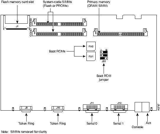
Step 8 When the top cover is off, set it aside. Figure B-2 to Figure B-5 show the layout of the system cards for models 2501 to 2504 and 2513 to 2515, respectively.
Figure B-2 : System Card Layout---Model 2501, 2502, 2503, and 2504 Routers
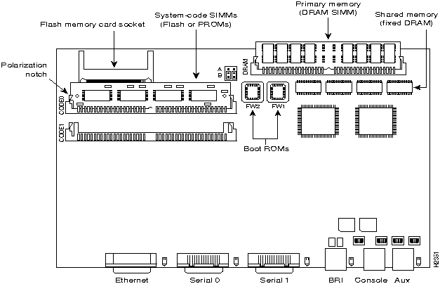
Figure B-3 : System Card Layout---Model 2513 Router
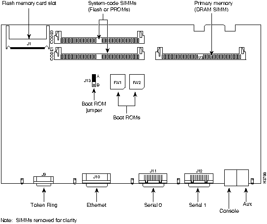
Figure B-4 : System Card Layout---Model 2514 Router
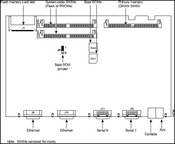
Figure B-5 : System Card Layout---Model 2515 Router
Upgrading the DRAM SIMM
This section describes how to upgrade the DRAM SIMM on the system card. You might need to upgrade the DRAM SIMM for the following reasons:
- You upgrade the Cisco IOS feature set or release.
- Your router maintains large routing tables or other memory-intensive features, such as spoofing or protocol translations.
To see how much memory is currently installed in the router, enter the show version command. Near the middle of the resulting output, a message similar to the following displays:
Cisco XXXX(68030) processor (revision X) with 4092K/2048K bytes of memory.
This line shows how much memory is installed (in this example, 4092K/2048K). The first number represents primary memory and the second number represents shared memory.
Tools Required
You will need the following tools to remove and replace the DRAM SIMM on the router:
- Medium-size flat-blade screwdriver (1/4 inch [0.625 cm])
- ESD-preventive wrist strap
- The DRAM SIMM required for your planned upgrade
DRAM SIMM Installation
Take the following steps to install the DRAM SIMMs:
Step 1 Power OFF the router.
Step 2 Attach an ESD-preventive wrist strap.
Step 3 Open the cover following the instructions in the section "Opening the Chassis" earlier in this appendix.
Step 4 Remove the existing DRAM SIMM by pulling outward on the connectors to unlatch them, as shown in Figure B-6. Be careful not to break the holders on the SIMM connector.
 Caution To prevent damage, do not press on the center of the SIMMs. Handle each SIMM carefully.
Step 5 Position the new SIMM so that the polarization notch is located at the left end of the SIMM socket. (See Figure B-6.)
Figure B-6 : Removing and Replacing the DRAM SIMM
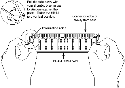
Step 6 Insert the new DRAM SIMM by sliding the end with the metal fingers into the SIMM connector socket at approximately a 45-degree angle to the system card. Gently rock the SIMM back into place until the latch on either side snaps into place. Do not use excessive force because the connector may break.
Step 7 Replace the router cover. Follow the instructions in the section "Closing the Chassis" later in this appendix.
Replacing the System-Code SIMMs
The system code (router operating system software) is stored in Flash memory SIMMs.
Tools Required
You will need the following tools to remove and replace the system-code SIMMs on the router:
- Medium-size flat-blade screwdriver (1/4 inch [0.625 cm])
- ESD-preventive wrist strap
- System-code SIMM(s)
Preparing to Install the System-Code SIMM
There are two system-code (Flash memory) SIMM sockets on the system board. If you want to install system-code SIMMs in both sockets, the SIMMs must be the same size. For example, if a 4-MB system-code SIMM is already installed in your router, the new SIMM must also be 4 MB. This upgrade would give you a total of 8 MB. You can verify how much Flash memory is already installed in your router by entering the show flash EXEC command.
 Caution The system code is stored on the Flash memory SIMMs, but new system-code SIMMs are shipped without preinstalled software. Before proceeding with this procedure, use the copy flash tftp EXEC command to back up the system code to a TFTP server.
Note For more information about the copy flash tftp command and other related commands, refer to the Cisco IOS configuration and command reference publications. These publications are available on the documentation CD that came with your router or you can order printed copies. Refer to the section "Ordering Documentation" in the chapter "Overview of the Router" for ordering information.
System-Code SIMM Replacement
Take the following steps to upgrade the system-code Flash memory SIMMs:
Step 1 If you have not already done so, enter the copy flash tftp EXEC command to back up the system code.
Step 2 Power OFF the router.
Step 3 Remove all cables from the rear panel of the router.
Step 4 Attach an ESD-preventive wrist or ankle strap.
Step 5 Open the chassis cover following the procedure in the section "Opening the Chassis" earlier in this appendix.
Step 6 Locate the system-code SIMMs on the system card, labeled CODE0 and CODE1. (See Figure B-2 to Figure B-5.)
Step 7 If necessary, remove the existing system-code SIMM by pulling outward on the connector holders to unlatch them. The connector holds the SIMM tightly, so be careful not to break the holders on the SIMM connector. (See Figure B-7.)
- If you are installing system-code SIMMs in both sockets (CODE0 and CODE1), both SIMMs must be the same size. For example, if a 4-MB system-code SIMM is already installed in your router, the new SIMM must also be 4 MB. Populate the SIMM socket labeled CODE0 first; then populate CODE1.

Caution To prevent damage, do not press on the center of the SIMMs. Handle each SIMM carefully.
Figure B-7 : Removing and Replacing the System-Code SIMM
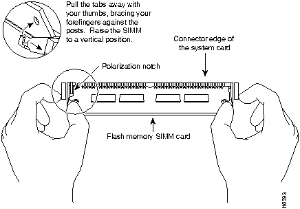
Step 8 Position the new SIMM so that the polarization notch is located at the left end of the SIMM socket.
 Caution To prevent damage, note that some Flash memory SIMMs have the components mounted on the rear side; therefore, when inserting the SIMM, always use the polarization notch as a reference and not the position of the components on the SIMM.
Step 9 Insert the new SIMM by sliding the end with the metal fingers into the appropriate SIMM connector socket (labeled CODE0 or CODE1) at approximately a 45-degree angle to the system card. Gently rock the SIMM back into place until the latches on both sides snap into place. Do not use excessive force because the connector may break.
Step 10 Replace the router cover following the procedure in the next section, "Closing the Chassis."
Closing the Chassis
This section describes the procedure for closing the chassis by replacing the cover.
Tools Required
You will need the following tools to replace the cover:
- Medium-size flat-blade screwdriver (1/4 inch [0.625 cm])
- Size M 3.5 hex-head nut driver (optional)
Replacing the Cover
Take the following steps to replace the cover:
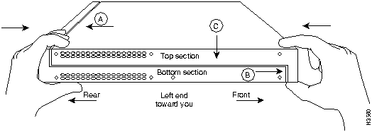
Step 1 Position the two chassis sections, as shown in Figure B-8.
Step 2 Referring to Figure B-8, press the two chassis sections together and ensure the following:
- The top section fits into the rear of the bottom section. (See A in Figure B-8.)
- The bottom section fits into the front of the top section. (See B in Figure B-8.)
- Each side of the top and bottom sections fits together. (See C in Figure B-8.)

Caution To fit the two sections together, it may be necessary to work them together at one end and then the other, working back and forth; however, use care to prevent bending the chassis edges.
Figure B-8 : Replacing the Chassis Cover
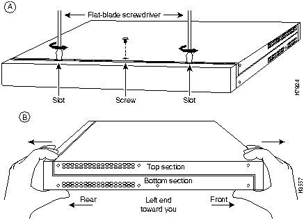
Step 3 When the two sections fit together snugly, turn the chassis so that the bottom is facing up, with the front panel toward you.
Step 4 Replace the cover screw. (See Figure B-1.) Tighten the screw to no more than 8 or 9 inch/pounds of torque.
Step 5 Reinstall the chassis on the wall, rack, desktop, or table.
Step 6 Replace all cables.
Copyright 1988-1996 © Cisco Systems Inc.
![]()
![]()
![]()
![]()


![]()

![]()
![]()

![]()
![]()

![]()
![]()
![]()
![]()
![]()
![]()
![]()
![]()