|
|
Maintaining and Upgrading the Router
This chapter contains information on maintenance procedures you might need to perform as your internetworking needs change.
If any upgrades requiring hardware or software replacement are necessary, a related publication called a configuration note will ship to you automatically with the parts.
This chapter contains the following sections:
![]()
This section explains how to open the chassis by removing the chassis cover.
The following tools are required to open the chassis:
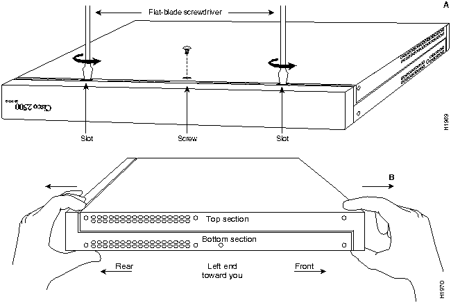
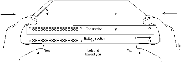
Refer to Parts A and B in Figure 5-2 and follow these steps to remove the chassis cover:
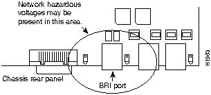
Figure 5-1 : BRI Port Location
Figure 5-2 : Chassis Cover Removal---Parts A (Top) and B (Bottom)
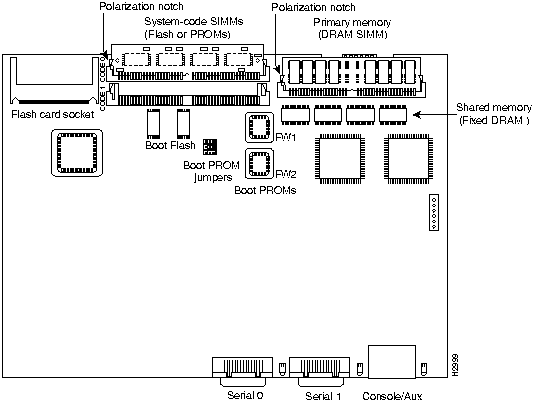
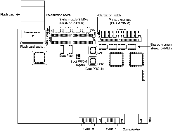
Figure 5-3 : System Board Layout---Model 2516 (Chassis, Fan, Power Supply Not Shown)
Your system is equipped with either boot Flash or boot PROMs depending on the size of the boot image for the system. If the boot image is less than 1 MB, the system is equipped with Boot PROMs. If the boot image is greater than 1 MB, the system is equipped with boot Flash.
To upgrade the boot image, either replace the boot PROMs or download the boot image from a Flash memory card to the boot Flash installed on the system board. This section explains how to upgrade the boot PROMs. For information about how to download the boot image from a Flash memory card, refer to the Upgrading Boot Image with Flash Memory Cards for Cisco 2500 Series Routers publication.
Table 5-1 lists the part numbers you need to upgrade the boot PROMs and indicates their installation socket. The part number is printed on a label attached to the boot PROM.
Table 5-1 : Boot PROM Part Numbers and Installation Sockets
Tools and Equipment Required for Replacing the Boot PROMs
The following tools and equipment are required to replace the boot PROMs:
Follow this procedure to replace the boot PROMs:
Installing Primary-Memory DRAM SIMMs
The router contains primary and shared memory. Primary memory stores the running configuration and routing tables. Shared memory is used for packet buffering by the router network interfaces. (See Figure Figure 5-3 for the location of primary and shared memory in your router.)
It might be necessary to expand primary memory by installing a DRAM SIMM if you are using very large routing tables or many protocols, or the router is set up as a connection device between large external networks and your internal network.
After booting your system, the system banner on the console screen displays only the amount of primary memory, in kilobytes (KB). The following example shows a system with 1 MB (1024 KB) of primary memory (shared memory is not displayed).The system does not display shared memory until later in the boot process.
The router has 2 MB of fixed DRAM memory and a DRAM SIMM socket for upgrading memory. You can upgrade primary memory by installing a 4-, 8-, or 16-MB DRAM SIMM in the DRAM SIMM socket. Table 5-2 lists the upgrade amounts and corresponding memory configurations.
Table 5-2 : DRAM SIMM Memory Configurations
Order DRAM SIMMs from Cisco Systems or an approved vendor. Table 5-3 lists the upgrade amounts and corresponding Cisco Systems product numbers.
Table 5-3 : Cisco Systems DRAM SIMMs
Table 5-4 lists approved 70 nanosecond (ns) DRAM SIMM vendors.
Table 5-4 : Approved DRAM SIMM Vendors
The type of memory installed, fixed DRAMs or a DRAM SIMM, effects the way shared and primary memory are allocated. Table 5-5 lists the types of memory (fixed DRAM or DRAM SIMM), how memory is allocated (as shared or primary memory), and the resulting total memory.
The following tools and equipment are required:
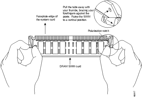
Following is the procedure for installing DRAM SIMMs:
Figure 5-4 : Removing and Replacing the DRAM SIMM
The system code (software) is stored on Flash or PROM SIMMs. It might be necessary to upgrade the system-code SIMM if you're upgrading to a system code that is too large for the existing system-code SIMM.
The system contains two system-code SIMM slots labeled CODE0 and CODE1. You can upgrade the system-code SIMM by replacing the existing SIMM in the CODE0 slot or installing an additional SIMM in the CODE1 slot. Table 5-6 lists the SIMM slots, CODE0 and CODE1, and the proper placement of SIMMs for the desired total SIMM memory.
Table 5-6 : System-Code SIMM Memory Configurations
The 80-pin Flash and PROM SIMMs must be purchased from Cisco Systems. Contact a customer service representative for more information.
Following is the procedure for upgrading the system-code Flash SIMMs:
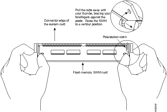
Figure 5-5 : Removing and Replacing the System-Code SIMM---Flash SIMM Shown
Upgrading Feature Sets with Flash Cards
The 2500 series router provides a Flash (PCMCIA) card slot permitting the upgrade of the feature set on your 2500 series router. The available feature sets are:
Flash card feature upgrades are available only from us. Contact a customer service representative for more information.
To upgrade the feature set using a Flash memory card, follow these steps:
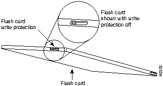
Figure 5-6 : Locating the Flash Memory Card Write Protection Switch
Figure 5-7 : Inserting the Flash Memory Card
Figure 5-8 : Example of a Flash Memory Card Upgrade Screen
Following is the procedure for replacing the cover.
Following are the tools required for replacing the cover:
After you perform the maintenance for your system, replace the cover by following these steps:
Figure 5-9 : Replacing the Chassis Cover
To recover a lost password, follow these steps:
Copyright 1988-1996 © Cisco Systems Inc.
![]()
![]()
Boot PROM Part Number
Installation Socket
17-1610-03
FW 1
17-1611-03
FW 2
![]()
System Bootstrap, Version (2.1), SOFTWARE
Copyright (c) 1986-1993 by cisco Systems
2500 processor with 1024 Kbytes of main memory
>
Upgrade DRAM
Memory Configuration
4 MB
1 MB x 36 DRAM SIMM
8 MB
2 MB x 36 DRAM SIMM
16 MB
4 MB x 36 DRAM SIMM
Upgrade DRAM
Cisco Systems Product Number
4 MB (1 MB x 36, 70 ns DRAM SIMM)
MEM1X4D=, MEM-6M=
8 MB (2 MB x 36, 70 ns DRAM SIMM)
MEM-1X8D=
16 MB (4 MB x 36, 70 ns DRAM SIMM)
MEM-1X16D=, MEM-18M=
Upgrade DRAM
Vendor
Vendor Part Number
4 MB (1 MB x 36, 70 ns DRAM SIMM)
Hyundai
HYM536100AM-70
Micron
MT9D136M-7
Mitsubishi
MH1M36ASDJ-7
Mitsubishi
MH1M36BNDJ-7
NEC
MC421000A36BE-70
OKI
MSC23136B-70BS12
Samsung
KMM5361003C-70
8 MB (2 MB x 36, 70 ns DRAM SIMM)
Smart Modules
SM536C2000-7
16 MB (4 MB x 36, 70 ns DRAM SIMM)
Hitachi
HB56D436SBR-7AGS
Hyundai
HYM536410M-70
Mitsubishi
MH4M36ANXJ-7
NEC
MC-424000A36BE-70
Samsung
KMM5364100A-70
Fixed DRAM Memory Installed
DRAM SIMM Memory Installed
Memory Allocated as Shared Memory
Memory Allocated as Primary Memory
Total Memory (Combined Shared and Primary Memory)
0 MB
4 MB
2 MB
2 MB
4 MB
0 MB
8 MB
2 MB
6 MB
8 MB
0 MB
16 MB
2 MB
14 MB
16 MB
2 MB
0 MB
1 MB
1 MB
2 MB
2 MB
4 MB
2 MB
4 MB
6 MB
2 MB
8 MB
2 MB
8 MB
10 MB
2 MB
16 MB
2 MB
16 MB
18 MB
![]()
SIMM Slot CODE0
SIMM Slot CODE1
Total SIMM Memory
4 MB
0 MB
4 MB
4 MB
4 MB
8 MB
8 MB
0 MB
8 MB
8 MB
8 MB
16 MB
CODE 0 and CODE 1 (shown in Figure 5-3).
![]()
![]()
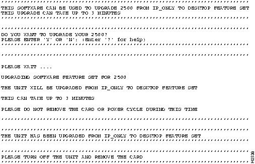
DO YOU WANT TO UPGRADE YOUR 2500?
PLEASE ENTER 'Y' OR 'N' : (Enter '?' for help)
Please Wait....
UPGRADING SOFTWARE FEATURE SET FOR 2500
THE UNIT WILL BE UPGRADED FROM IP-ONLY TO DESKTOP FEATURE SET
THIS CAN TAKE UP TO 3 MINUTES
PLEASE DO NOT REMOVE THE CARD OR POWER CYCLE DURING THIS TIME
THE UNIT HAS BEEN UPGRADED FROM IP-ONLY TO DESKTOP FEATURE SET
PLEASE TURN OFF THE UNIT AND REMOVE THE CARD
![]()
>
o/r 0x041
>
i
--- System Configuration Dialog ---
Press RETURN to get started!
Router(boot)>
Router(boot)#
![]()
![]()
![]()
![]()
![]()
![]()
![]()
![]()