Banner
HomeTOCPrevNextGlossSearchHelp

Table of Contents

Troubleshooting TCP/IP Connectivity

Troubleshooting TCP/IP Connectivity

Troubleshooting TCP/IP Connectivity

This chapter presents protocol-related troubleshooting information for Transmission Control Protocol/Internet Protocol (TCP/IP) connectivity problems. The chapter consists of the following sections:

Each symptom module is divided into the following sections:


TCP/IP Route Redistribution and Access Control Scenario

Many of the largest internetworks employ TCP/IP as their backbone network protocol. However, this does not mean that these networks employ universal internetworking implementations. In fact, TCP/IP internetworks---sometimes comprising thousands of internetworking nodes---can span organizational domains that employ completely different topologies, routing protocols, and possibly conflicting administrative objectives. The challenge is to provide the requisite level of connectivity between hosts in different domains and on different major networks, while providing adequate security for each organization attached to the internetwork. This scenario focuses on the issue of balancing connectivity and security.


Symptoms

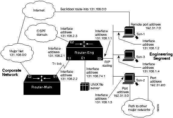
This scenario addresses connectivity problems in TCP/IP internetworks. Figure 11-1 illustrates interconnections from one subnet to a corporate network as well as interconnections to external networks.

Figure 11-1 : TCP/IP Internetwork Connectivity Scenario Map
s2258.gif

Sun-1, Sun-2, and Sun-3 on the Ethernet segment attached to Router-Eng are unable to communicate with hosts in the main corporate network or outside the organization through Router-Eng. Several backdoor routes also exist, which allow other networks to access the engineering segment.

Because external access is not being reliably controlled and because users on the engineering segment are unable to get through to the corporate network via Router-Eng, this scenario represents a security problem as well as a connectivity problem.


Environment Description

The relevant elements of the internetworking environment shown in Figure 11-1 can be summarized as follows:


Diagnosing and Isolating Problem Causes

Given the situation, the following candidates are likely causes for interconnection problems:

The next step is to analyze each potential cause as the problem source and then test the network to determine whether it is operational after each modification is made. The following discussion considers these possible problems and alternatives for providing the proper access and security.


Isolating Router Software Configuration Problems

Because the UNIX workstation-based routers on the engineering segment are using RIP to route among themselves, while the corporate network uses IGRP, the first configuration issue to consider is route redistribution.

Step 1 Use the write terminal privileged EXEC command to review the configuration on Router-Eng. In order for RIP routes and IGRP routes to be passed between the engineering segment and the corporate network, Router-Eng must be configured for redistribution.

Step 2 Assuming that Router-Eng does not have redistribution configured, add appropriate redistribution commands.

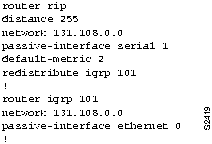
Figure 11-2 illustrates a partial configuration for Router-Eng that establishes RIPtoIGRP route redistribution for this network and prevents IGRPtoRIP route redistribution.

Figure 11-2 : RIP-to-IGRP Route Redistribution Configuration Example

s2419.gif

Note the following points about Figure 11-2:

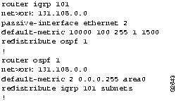
Figure 11-3 shows a partial configuration for Router-Eng that redistributes IGRP routes into the OSPF domain and OSPF routes back into IGRP.

Figure 11-3 : IGRP-to-OSPF Route Redistribution Configuration Example

s2643.gif

Note the following points about Figure 11-3:

Step 3 At this point, you might perform an extended ping from Router-Main to one or more of the UNIX nodes on the engineering segment. Assuming that no access controls are in place, the ping should be successful, and Sun-1, Sun-2, and Sun-3 should be able to communicate with the corporate network resources.

However, setting up redistribution does not provide any means of blocking the uncontrolled backdoor access available through the asynchronous lines on the UNIX routers (Sun-1 and Sun-2).

Step 4 The next step is to set up access lists to allow Sun-1, Sun-2, and Sun-3 on the engineering segment to access the corporate network but to block access from outside the corporation to resources on the corporate network.

Step 5 Figure 11-4 illustrates additional commands for Router-Eng to control access to the corporate network.

Figure 11-4 : Access Control Additions to Router-Eng Configuration

s2420.gif

Access list 20 and the ip access-group 20 interface configuration command (applied to serial 1) permit Sun-1, Sun-2, and Sun-3 on Ethernet0 to make connections through serial 1. However, other access via serial 1 is blocked.

Figure 11-5 illustrates a modification to the access list specification for Router-Eng that provides a slightly different access control. Access list 21 also illustrates how order can be crucial in access list specifications. Here, the first line of access list 21 specifies that if the packet comes from address 131.108.1.4, it will be blocked (denied). If the packet is not from this source address, the next line is read. This line indicates that any packets from any other node on subnet 131.108.1.0 are permitted on serial 1---specifically packets from 131.108.1.2 and 131.108.1.3.

If the permit and deny statements for access list 21 are swapped, all packets on subnet 131.108.1.0 are permitted. The second line is never applied, because 131.108.1.4 has already passed the first list entry. All other traffic is denied.

Figure 11-5 : Standard Access Control for Router-Eng Configuration

s2421.gif

Another access list variation is an extended access list. Figure 11-6 illustrates an extended access list that is used to limit access to resources by Sun-1 and Sun-2. This access lists uses source and destination filtering to control traffic from the UNIX nodes on Ethernet0. As specified, Sun-1 and Sun-2 only can access resources directly connected to 131.108.0.0. Traffic intended for any other network will not be allowed out Serial1.

Figure 11-6 : Extended Access Control for Router-Eng Configuration

s2422.gif


Problem Solution Summary

This scenario focused on solving two problems in TCP/IP internetworks:

Of these two, implementing redistribution is relatively straightforward, while access lists can be fairly complicated and can yield unexpected results.

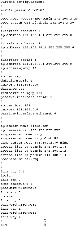
Figure 11-7 illustrates a complete router configuration for Router-Eng (obtained by using the write terminal privileged EXEC command).

Figure 11-7 : Complete Example Configuration for Router-Eng

s2423.gif


TCP/IP Connectivity Symptoms

The symptom modules in the following sections pertain to TCP/IP internetwork problems. Unless otherwise indicated, each module is presented as a set of general problems. Where there are special considerations associated with a situation, notes are included.


Note The symptoms are generic in nature. However, when host configuration problems are discussed, they are addressed assuming UNIX end systems. Equivalent kinds of actions may be applicable to non-UNIX hosts as well, but the discussion here does not address non-UNIX end station problems.


Host Cannot Access Offnet Hosts

Symptom: Host-A is unable to communicate with Host-B on another network. When you attempt to make a connection to an intervening router, you may or may not be able to make a successful connection. For example, you can ping Router-X but not Router-Y. In either case, you are unable to connect to the target host on the other side of the router. This situation is illustrated in Figure 11-8.

Figure 11-8 : Host-A Cannot Communicate with Host-B over Routers

s1265a.gif

Table 11-1 outlines possible causes and suggested actions when a host cannot access offnet hosts.

Table 11-1 : TCP/IP: Host Cannot Access Offnet Hosts

Possible Causes Suggested Actions
No default gateway specification Step 1 Determine whether a default gateway is included in the routing table of the host attempting to make a connection (Host-A in Figure 11-8). Use the following UNIX command:
netstat -rn

Step 2 Look at the output of this command for a default gateway specification.
Step 3 If the default gateway specification is incorrect, or if it is not present at all, you can change or add a default gateway using the following UNIX command at the local host:
route add default address 1

(address is the IP address of the default gateway; the value 1 indicates that the specified node is one hop away)

You may need to reboot the host for this change to take effect.

Step 4 To automate this as part of the boot process, specify the default IP address of the gateway in the following UNIX host file:
/etc/defaultrouter

This filename may be different for your particular version of UNIX. Or, if you working with a PC or a Macintosh, consult the corresponding documentation to determine how to set the default gateway.
Misconfigured subnet mask Step 1 Check the following two locations on the local host for possible subnet mask errors:
/etc/netmasks

/etc/rc.local

Step 2 Fix the netmask if is specified incorrectly, or add the netmask if it is missing.
Or, if you working with a PC or a Macintosh, consult the corresponding documentation to determine how to set the subnet mask.
Host interface is down Step 1 Verify that the host interface is working.
Router between hosts is down Step 1 Use the ping command to determine whether the router is reachable.
Step 2 If the router does not respond, isolate the problem and repair the broken interconnection.
Step 3 For more information, refer to the section "Developing a Strategy for Isolating Problems" in the "Troubleshooting Overview" chapter, and to the "Troubleshooting Router Startup Problems" chapter.


Host Cannot Access Certain Networks

Symptom: Host cannot access certain networks on the other side of a router. Some networks might be accessible. Table 11-2 outlines possible causes and suggested actions when a host cannot access certain networks.

Table 11-2 : TCP/IP: Host Cannot Access Certain Networks

Possible Causes Suggested Actions
No default gateway Step 1 Check the host for proper default gateway specification and modify or add a default gateway specification as required. For more information, see Table 11-1.
Misconfigured access list (getting routing information for some routes, but not others) Step 1 Use the show ip routes EXEC command to check routing table and use the appropriate debug command (such as debug ip igrp events and debug ip rip) to check protocol exchanges.
Step 2 Look for information concerning the network with which you are unable to communicate.
Step 3 Check the use of access lists on the routers in the path and make sure that a distribute-list or distance router configuration command does not filter out the route.
Step 4 Temporarily remove ip access-group interface configuration commands to disable access lists, and use the trace or ping EXEC command with the Record Route option set to determine whether traffic can get through when the access list is removed.
Discontinuous network addressing due to network design Step 1 Use the show ip route EXEC command to determine which routes are known and how they are being learned.
Step 2 Use the trace or ping command to see where traffic is stopping.
Step 3 Fix topology or reassign addresses to include all appropriate network segments in the same major network. For additional information, refer to the "Users Cannot Make Connections when One Parallel Path Is Down" symptom module, later in this chapter.
Discontinuous network addressing due to link failure Step 1 Restore disabled link.
Step 2 If a link failure occurs, and you cannot use a parallel path, examine network address assignments.
Step 3 If the link failure results in a discontinuous network because one network has different points of contact with two now isolated subnets of a different major network, assign secondary addresses along the backup path to restore major network connectivity.


Connectivity Available to Some Hosts but Not Others

Symptom: Hosts on a network can communicate with specific hosts on the other side of a router, but are unable to communicate with certain other hosts. Table 11-3 outlines possible causes and suggested actions when connectivity is not available to all hosts.

Table 11-3 : TCP/IP: Connectivity Not Available to all Hosts

Possible Causes Suggested Actions
Misconfigured subnet mask Step 1 Check subnet masks on hosts and routers.
Step 2 Look for a mismatch between subnet masks. What may be a specific host address to one host may become a subnet broadcast when a different mask is applied at a router.
Step 3 Fix the subnet mask on the host or router as required. SeeTable 11-1 and Table 11-8 for additional information.
Misconfigured access list (host is denied by some router in the path) Step 1 Determine where packets are being dropped by using the trace or ping EXEC command out through the path.
Step 2 If you can identify the router that is stopping traffic, use the write terminal privileged EXEC command to see whether an access list is being used. You also can use the show access-lists and show ip interface EXEC commands in combination to determine whether access lists are being used.
Step 3 Temporarily disable the access list.
Step 4 Use ping or telnet to see whether traffic can get through the router.
Step 5 If traffic can get through, review the access list and its associated commands for proper authorization.
Missing default gateway specification on remote host Step 1 Have someone log in to the remote host and try to access an offnet host.
Step 2 Check the remote host for the proper default gateway specification and modify or add a default gateway specification as required. For more information, see Table 11-1.


Some Services Are Available, Others Are Not

Symptom: In some cases, you might be able to get through to hosts using some protocols, but cannot get through using others. For instance, you might be able to ping a host and FTP to a host, but Telnet does not get through. Table 11-4 outlines a possible cause and suggested actions when not all services are available.

Table 11-4 : TCP/IP: Not All Services Are Available

Possible Cause Suggested Actions
Misconfigured extended access list Step 1 Use the trace command to determine the path taken to reach remote hosts.
Step 2 (Optional) On each router in the path, enable debug ip icmp command.
Any router that returns "unreachable" is suspect.

Step 3 If you can identify the router that is stopping traffic, use the write terminal privileged EXEC command to see whether an access list is being used. You also can use the show access-lists and show ip interfaces EXEC commands in combination to determine whether access lists are being used.
Step 4 Temporarily disable the access list.
Step 5 Determine whether traffic can get through the router.
Step 6 If traffic can get through, review the access list and its associated commands for proper authorization.
In particular, look for extended access lists that specify TCP ports.

Step 7 If an extended access list specifies a TCP port, make sure that the access list explicitly permits all the necessary TCP ports.

For information on how to create access-lists, refer to the Router Products Configuration Guide.


Users Cannot Make Connections when One Parallel Path Is Down

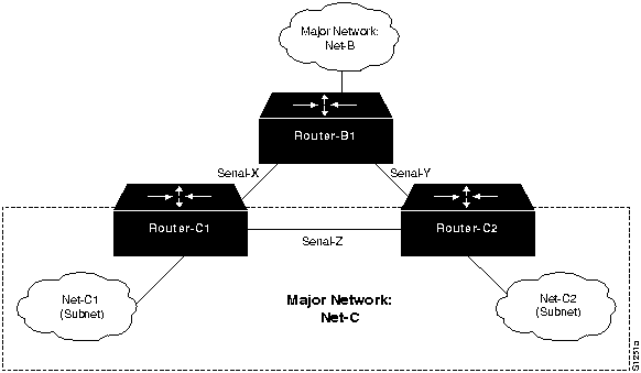
Symptom: In configurations that feature multiple paths between networks, there is no communication over the alternative routes when one of the parallel links breaks.

Figure 11-9 illustrates one example of a situation in which this lack of communication can occur. Here, one major network (Net-B) has two or more access points into another major network (Net-C), while a third link joins two separate subnets of Net-C. Details are provided in Table 11-5.

Figure 11-9 : Problem Parallel Path Topology Example

s1251a.gif

Table 11-5 outlines possible causes and suggested actions when users cannot make connections when one parallel path is down.

Table 11-5 : TCP/IP: Users Cannot Make Connections when One Parallel Path Is Down

Possible Causes Suggested Actions
Discontinuous network due to failure. If Serial-Z is lost, traffic cannot traverse from Net-C1 to Net-C2 through RouterB1 Step 1 Bring the link back up.
Step 2 As an alternative, use a secondary IP address configuration to ensure that all interfaces are included in the same major network.
Refer to Figure 11-9. If Serial-Z is lost, Major Network Net-C becomes a discontinuous network because Router-B1 is separating the two Net-C subnets (Net-C1 and Net-C2).

Traffic between Router-C1 and Router-C2 will not get through Router-B1 because Router-B1 assumes that they are directly connected.
Routing has not converged Step 1 Assuming that you have used secondary addresses, examine routing tables for routes that are listed as "possibly down." If this entry is found, the routing protocol has not converged.
Step 2 Wait for the routing protocol to converge. Examine the routing table later.
Misconfigured access lists or other routing filters Step 1 Check for access lists in the secondary path.
Step 2 If present, disable and determine whether traffic is getting through.
If traffic is getting through, an access list and accompanying commands may be causing traffic stoppage.

Step 3 Evaluate and reconfigure access lists as necessary.
Errors on serial link Step 1 Use the show interfaces serial EXEC command to look for input on the serial interface.
Step 2 For more information, see the "Troubleshooting Serial Line Problems" chapter.
Errors on Ethernet link Step 1 Use a time domain reflectometer (TDR) to find any unterminated Ethernet cables.
Step 2 Check host cables and transceiver cables to determine whether any are incorrectly terminated, overly long, or damaged.
Step 3 Look for a jabbering transceiver attached to a host.


Router Sees Duplicate Routing Updates and Packets

Symptom: Router sees duplicate routing updates on different interfaces. Network users might experience sudden loss of connections and extremely poor performance. Router sees other routers and hosts on multiple interfaces. Table 11-6 outlines a possible cause and suggested actions when a router sees duplicate routing updates and packets.

Table 11-6 : TCP/IP: Router Sees Duplicate Routing Updates and Packets

Possible Cause Suggested Actions
Bridge or repeater in parallel with a router, causing updates and traffic to be seen as coming from both sides of an interface Step 1 Use the show ip routes EXEC command to examine routes for each interface.
Step 2 Look for routers that are known to be remote to the network connected to the router.
Routers that are listed but are not attached to any directly connected networks are a likely problem.

Step 3 Look for paths to the same networks with the same cost on multiple interfaces.
Step 4 Another test is to use debug EXEC commands to examine protocol routes for each interface, which will identify both the source of the routing update and the inbound interface. For example, debug ip rip shows RIP-specific events.
Step 5 If you determine that there is a parallel bridge, disable the bridge or configure the bridge with access filters that block routing updates.


Routing Works for Some Protocols, Not for Others

Symptom: Some protocols are routed, others are not. Telnet, for example, works from a host on one network to a host on another network on the other side of a router, but FTP does not. Perhaps Domain Name Service (DNS) works with your own domain, but does not work for external domains. Table 11-7 outlines a possible cause and suggested actions when routing does not work for all protocols.

Table 11-7 : TCP/IP: Routing Does Not Work for All Protocols

Possible Cause Suggested Actions
Misconfigured access list Step 1 Use the ping and trace EXEC commands to help determine which routers are in the path and should be investigated for misconfigured access lists.
Step 2 Use the write terminal privileged EXEC command on a router that may be stopping traffic.
Step 3 Look for any access list in the configuration.
Step 4 Temporarily disable the access list and monitor traffic to and through the suspect router.
If the router is allowing previously blocked traffic through, the problem is probably in the access list.

Step 5 Make sure that you explicitly permit desired traffic; otherwise, unpermitted traffic is blocked by the implicit deny statement that ends all access lists.


Router or Host Cannot Reach Nodes on the Same Network

Symptom: A router or host is unable to communicate with other routers or hosts known to be connected to the same network. Table 11-8 outlines possible causes and suggested actions when a router or host cannot reach nodes on the same network.

Table 11-8 : TCP/IP: Router or Host Cannot Reach Nodes on the Same Network

Possible Causes Suggested Actions
Subnet mask configuration mismatch between router and host
Step 1 Test connectivity to the destination using the ping command at the router or host, as discussed in the section "Developing a Strategy for Isolating Problems" in the "Troubleshooting Overview" chapter.
Step 2 If you can ping from the local host to the local router (but not to a remote host), and if you can ping from the local router to the remote host, there is probably a subnet mask configuration problem on your local host or router.
Step 3 Check host and router configurations for a subnet mask mismatch. Make sure that all subnet masks match.
NOTE: Masks might not match if proxy ARP is being used. Refer to Request for Comments (RFC) 1027 for more information about using proxy ARP.

For notes about host subnet masks, refer to the "Host Cannot Access Offnet Hosts" symptom module, earlier in this chapter.

For information about subnet mask conflicts, refer to the section "Note about IP Addresses and Subnet Masks" later in this chapter.
Misconfigured access list Step 1 See Table 11-7 for suggested actions.
No default gateway specified Step 1 Check the remote host for the proper default gateway specification and add or modify the specification as necessary. For more information, see Table 11-1.
Step 2 Check host and router configurations for static routes.
Step 3 If static routes exist and no default gateway is specified, access to some hosts and routers might be possible, while others are unavailable. You have several options for resolving this inconsistency:
  • Specify a default gateway on your host as described in Table 11-1.

  • Enable proxy ARP on the router; make the local cable the default network (network 0 for RIP).

  • Run the Gateway Discovery Protocol (GDP), which allows dynamically defined default gateways, on the host (Berkeley Software Distribution [BSD] UNIX host only).

  • Run a routing protocol (such as RIP) on the host. Note that there might be high host processing overhead associated with this option.
Incorrect network specified Step 1 Enable debug arp and ping hosts. Look for responses that indicate you are on the incorrect network.
For example, you believe you are on the physical network attached ethernet 0, but you are really on the physical network attached ethernet 1. In such a case, you might be able to reach all devices on your local network (ethernet 1), and the router might forward your packets. However, because of your network address, the router is operating as if you are on ethernet 0 instead of your correct location on ethernet 1.

Step 2 Move your host so that its address corresponds to the correct network. Or, change the address of your host to match the cable to which it is attached.


Note about IP Addresses and Subnet Masks

In most IP networks, routers and hosts should agree on their common subnet mask. If a router and a host disagree on the length of the subnet mask, packets might not be routed correctly. Consider the situation described in Table 11-9.

A host interprets a particular address (192.31.7.49) as being Host 1 on the third subnet (subnet address 48). However, because it is using a different subnet mask, the router interprets the address as belonging to Host 17 on the first subnet (subnet address 32). Depending on its configuration, the router drops any packet destined for 192.31.7.49 or sends it out on the wrong interface.

Table 11-9 : Comparison of Host and Router Subnet Mask Effects

Routing Info Host Value Router Value
Destination IP address 192.31.7.49 192.31.7.49
Subnet mask 255.255.255.240 255.255.255.224
Interpreted address Subnet address 48, host 1 Subnet address 32, host 17


OSPF Networks Are Not Advertised

Symptom: OSPF routes and networks are not being advertised to other routers. Routes are not in the routing table, and hosts are unable to communicate. Table 11-10 lists a possible cause and suggested actions when OSPF networks are not being advertised.

Table 11-10 : TCP/IP: OSPF Networks Are Not Advertised

Possible Cause Suggested Actions
Improper OSPF mask specification Step 1 Use the show ip ospf EXEC command to determine which interfaces are configured to run OSPF.
Step 2 Use the write terminal privileged EXEC command to check the configuration of the router.
Step 3 Look for network router configuration commands. Make certain the network masks match the network requirements. For example:

network 131.108.0.0 0.0.255.255 area 0 


With this network mask, an interface with an address of 120.110.7.2 is not in any area and is not advertised, which prevents other routers from seeing this network. Adding the following configuration command configures OSPF on this interface and allows network advertisements over this interface:


network 120.110.7.2 0.0.255.255 area 0


OSPF Routers Do Not Communicate

Symptom: Connectivity fails for OSPF routers and networks. Hosts or routers do not communicate with one another. Table 11-11 lists possible causes and suggested actions for OSPF routers that do not communicate.

Table 11-11 : TCP/IP: OSPF Routers Do Not Communicate

Possible Causes Suggested Actions
Network is down Step 1 Use the ping command to determine whether the router is reachable.
Step 2 If the router does not respond, isolate the problem and repair the broken interconnection.
Step 3 For more information, refer to the section "Developing a Strategy for Isolating Problems" in the "Troubleshooting Overview" chapter, and to the "Troubleshooting Router Startup Problems" chapter.
Misconfigured access list Step 1 See Table 11-7 for suggested actions.


OSPF Protocols Fail to Work on New Interfaces

Symptom: New interfaces are added to a router, but the protocol configured for the router does not work on the new interfaces. New interfaces in the router are assigned to a different major network than existing interfaces, and the routing protocol fails. Table 11-12 lists a possible cause and suggested actions when OSPF routing protocols fail to work on new interfaces.

Table 11-12 : TCP/IP: OSPF Protocols Fail to Work on New Interfaces

Possible Cause Suggested Actions
Missing network router configuration command Step 1 Use the show ip ospf interfaces EXEC command to find out which interfaces have OSPF enabled.
Step 2 Use the write terminal privileged EXEC command to list the router configuration if the show ip ospf interfaces output does not show OSPF running on the new interface.
Step 3 Look for the network router configuration command. Make sure that the networks on which OSPF runs include the new interfaces and that they define the area IDs for those interfaces.


OSPF Routers Are Not Receiving Routing Information from Other Areas

Symptom: OSPF nodes in one area are not seeing routing information for other areas. Some hosts being are unable to communicate with hosts in other areas, and routing table information is incomplete. Table 11-13 lists possible causes and suggested actions when OSPF routers are not receiving routing information from other areas.

Table 11-13 : TCP/IP: OSPF Routers Not Receiving Routing Information from Other Areas

Possible Causes Suggested Actions
A specific area is isolated from the OSPF backbone Step 1 Use the write terminal privileged EXEC command to verify that at least one border router exists for each area. Area border routers must have area 0 defined by the network router configuration command, and the backbone area (area 0) must not be partitioned.
Step 2 If no area border router exists in an area, add one where appropriate.
Hello timer or dead timer intervals are mismatched in the OSPF domain Step 1 Use the write terminal privileged EXEC command at each router and make sure that values for the Hello timer and dead timer match for all routers in the OSPF domain.
Step 2 Change timer values as required.
Note that timer values are extremely important when Cisco routers interoperate with routers from other vendors.
A virtual link is configured through a stub area Step 1 A stub area cannot be used as a transit area for virtual links. Use the write terminal privileged EXEC command and look for the following router configuration commands:


area area-id stub


area area-id virtual-link router-id


Step 2 Verify that no virtual link is configured through a router defined as an area stub.
IGRP or RIP is not redistributed correctly into OSPF Step 1 The subnet keyword must be included when IGRP or RIP is redistributed into OSPF; otherwise, only major routes (not subnet routes) are redistributed.
Step 2 Use the write terminal privileged EXEC command to check that the subnet keyword is used with the redistribute router configuration command.
Step 3 Add the subnet keyword as appropriate.
A virtual link is misconfigured Step 1 A virtual link requires that the routers at each area boundary of the transit area point to one another. (See Figure 11-10.)
Step 2 Use the show ip ospf EXEC command to get the border router ID on each side of the transit area (area 1).
Step 3 Add or modify the area area-id virtual-link router-id router configuration command. For example, in Router-A create a virtual link to Router-B:


area 1 virtual-link 108.31.1.1


And in Router-B, create a virtual link to Router-A:


area 1 virtual-link 121.10.1.1

Figure 11-10 : Virtual Links and Transit Areas

s1885.gif


OSPF Routers Are Not Communicating Dynamically

Symptom: OSPF routers are not communicating dynamically with their neighbors. Some routers can communicate, but some routers are unreachable. Table 11-14 lists possible causes and suggested actions when OSPF routers are not communicating dynamically.

Table 11-14 : TCP/IP: OSPF Routers Not Communicating Dynamically

Possible Causes Suggested Actions
Hello timer or dead timer intervals are mismatched in the OSPF domain Step 1 Use the show ip ospf neighbor EXEC command to identify the OSPF neighbors of the router.
Step 2 If the output does not list an expected neighbor, use the show ip ospf interfaces EXEC command to see the Hello and dead timer intervals configured on the interface. Compare these values with the configured value on the expected neighbor. If there is a mismatch, reconfigure the timer values, so they are the same on the router and its neighbor.
Note that timer values are extremely important when Cisco routers interoperate with routers from other vendors.
A virtual link is configured through a stub area Step 1 See Table 11-13 for suggested actions.


OSPF External Routes Incorrectly Advertised into Stub Area

Symptom: OSPF external routes are incorrectly advertised into a stub area. Some routers can communicate, but specific routers or hosts are unreachable. Table 11-15 lists a possible cause and suggested actions when OSPF external routes are incorrectly advertised into a stub area.

Table 11-15 : TCP/IP: OSPF External Routes Incorrectly Advertised into Stub Area

Possible Cause Suggested Actions
Not all routers in stub area are configured as stubs Step 1 Use the write terminal privileged EXEC command to list the configuration for each router in the stub area.
Step 2 Verify that the configuration of all routers in the stub area includes the area area-id stub command.


IGRP Routers Do Not Communicate

Symptom: Connectivity fails for IGRP routers and networks. Hosts or routers do not communicate with one another. Table 11-16 lists possible causes and suggested actions when IGRP routers are not communicating.

Table 11-16 : TCP/IP: IGRP Routers Not Communicating

Possible Causes Suggested Actions
Network is down Step 1 Use the ping command to determine whether the router is reachable.
Step 2 If the router does not respond, isolate the problem and repair the broken interconnection.
Step 3 For more information, refer to the section "Developing a Strategy for Isolating Problems" in the "Troubleshooting Overview" chapter, and to the "Troubleshooting Router Startup Problems" chapter.
Misconfigured access list Step 1 See Table 11-7 for suggested actions.


Traffic Is Not Getting through Router Using Redistribution

Symptom: Traffic is not getting through a router that is redistributing routes between two different routing domains---typically RIP and IGRP. Observed symptoms range from poor performance to no communication at all. Poor performance can occur when nonoptimal routes are used because the best path is blocked by a misconfigured redistribution. Table 11-17 outlines possible causes and suggested actions when traffic is not getting through a router using route redistribution.

Table 11-17 : TCP/IP: Traffic Not Getting through Router Using Redistribution

Possible Cause Suggested Actions
Missing default-metric command Step 1 Use the write terminal privileged EXEC command to check the router configuration for the default-metric router configuration command.
Step 2 If the default-metric router configuration command is missing, add it to the configuration, using appropriate values.
Problem with the default administrative distance Step 1 Determine the policy for identifying how much you trust routes derived from different domains.
Problems occur when a particular route is, by default, trusted less than another, but actually is the preferred route.

Step 2 Use the distance router configuration command to vary the level of trust associated with specific routing information as necessary.
Missing redistribute command Step 1 Check router configuration using the write terminal privileged EXEC command.
Step 2 If the redistribute router configuration command is missing, add it to the configuration. For more information, refer to the Router Products Configuration Guide and Router Products Command Reference publications.
Misconfigured access list Step 1 See Table 11-7 for suggested actions.
Misconfigured distribute-list command Step 1 Use the write terminal privileged EXEC command to check the configuration of the router.
Step 2 Verify that any distribute-list router configuration command specifies the correct access list.


IGRP or RIP Fail to Work on New Interfaces

Symptom: New interfaces are added to a router, but the protocol configured for the router does not work on them. The new interfaces are assigned to a different major network than existing interfaces, and the routing protocol fails. Table 11-18 lists a possible cause and suggested actions when IGRP or RIP fail to work on new interfaces.

Table 11-18 : TCP/IP: IGRP or RIP Fail on New Interfaces

Possible Cause Suggested Actions
Missing network router configuration command Step 1 Use the write terminal privileged EXEC command to list the configuration of the router.
Step 2 When more than one major network is configured in a router, add the network router configuration command. For example, a router that runs IGRP and that supports two major networks, such as 128.10.0.0 and 192.31.7.0, must have the following commands in its configuration:

router igrp 109


network 128.10.0.0


network 192.31.7.0


Redistribution route-map Commands Behave Unexpectedly

Symptom: A series of redistribute and route-map router configuration commands allow some routes to be redistributed but deny others. Also, some routes that are configured to deny redistribution are redistributed. Table 11-19 lists possible causes and suggested actions when redistribution problems occur with the redistribute and route-map router configuration commands.

Table 11-19 : TCP/IP: Redistribution route-map Commands Behave Unexpectedly

Possible Causes Suggested Actions
Sequence numbers cause some conditions to be tested before others Step 1 Use the write terminal privileged EXEC command to display the configuration of the router.
Step 2 Look at the sequence numbers assigned to the redistribute router configuration commands. Lower sequence numbers are tested before higher sequence numbers, regardless of their listed order.
Step 3 Modify the sequence numbers so the conditions are tested in the desired order.
Missing condition in the series of router redistribution commands Step 1 Use the write terminal privileged EXEC command to display the router configuration.
Step 2 Look at the configuration and be sure that conditions to permit or deny certain redistributions are included.
Step 3 Add or modify conditions that determine when a route is redistributed.

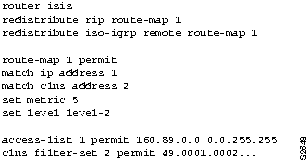
Consider the example configuration shown in Figure 11-11 and the modified configuration shown in Figure 11-12. In Figure 11-11, a router is configured to redistribute RIP and ISO-IGRP routes into an Intermediate System-to-Intermediate System (IS-IS) level-2 LSP with a metric of 5. All destinations on the RIP network with address 160.89.0.0 are redistributed, as are all ISO-IGRP routes with a prefix of 49.0001.0002.

Figure 11-11 : Configuration Example for Redistribution Using Route Maps

s2648.gif

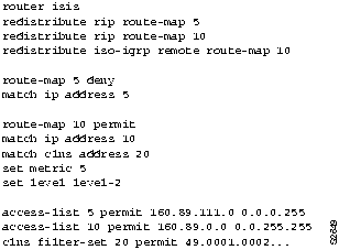
However, you want to exclude a particular subnet from RIP route redistribution. The additional configuration commands shown in Figure 11-12 exclude subnet 160.89.111.0. By assigning a sequence number of 5, you ensure that this address will be excluded before the more general access for 160.89.0.0 is processed. The redistribute router configuration commands, with their sequence numbers, can be entered in any order, making it easier to modify a router configuration. You can add new permit and deny access lists at the end of the configuration file instead of having to reenter all access lists in the desired order.

Figure 11-12 : Modified Configuration Example for Redistribution Using Route Maps

s2649.gif


Poor or Lost Connectivity in Multiprotocol Network Running Enhanced IGRP

Symptom: Nodes on a multi-protocol internetwork running IP Enhanced Interior Gateway Routing Protocol (Enhanced IGRP) and any combination of IGRP, RIP, OSPF, or other typically used routing protocols experience poor connectivity or lost connectivity with other nodes on the network. Table 11-20 describes possible causes and suggested actions when connectivity problems occur between nodes in a multiprotocol and IP Enhanced IGRP environment.

Table 11-20 : TCP/IP: Poor or Lost Connectivity in Multiprotocol Internetwork Running IP Enhanced IGRP

Possible Causes Suggested Actions
IGRP, RIP, OSPF or other routing protocols are not enabled on boundary routers. Step 1 Issue the write terminal privileged EXEC command on the boundary routers. Look for the router global configuration commands associated with the routing protocols you are running.
Step 2 If the applicable commands are not present, enable the routing protocols you want to use with the correct router global configuration command.
Step 3 In router configuration mode, enter the appropriate network commands to associate networks with the routing process, as applicable. For example, to enable IGRP routing on networks 193.166.66.12 and 193.168.25.25, enter the following configuration commands:

Router(config)# router igrp 100


Router(config-router)# network 193.166.66.0


Router(config-router)# network 193.168.25.0


Step 4 For complete information on configuring IGRP, RIP, OSPF, Border Gateway Protocol (BGP), or IS-IS, see the Router Products Configuration Guide and the Router Products Command Reference publications.
Enhanced IGRP routing is not enabled on boundary routers. Step 1 Issue the write terminal privileged EXEC command on the boundary routers. Look for the router eigrp global configuration command.
Step 2 If the command is not present, enable Enhanced IGRP routing using the router eigrp global configuration command.
Step 3 In router configuration mode, enter the appropriate network commands to associate networks with the Enhanced IGRP routing process. For complete information on configuring Enhanced IGRP, see the Router Products Command Reference and the Router Products Configuration Guide publications.
Routes are not being redistributed between routing protocols. Step 1 Issue the write terminal privileged EXEC command on the boundary routers. Examine the router global configuration command entries for the enabled routing protocols (such as IGRP, OSPF, Enhanced IGRP, and so forth) to see if the autonomous system designated for each protocol is the same.
Step 2 If the router commands indicate autonomous systems, routes will not be automatically redistributed between the routing protocols. Route redistribution must be manually configured using the redistribute router configuration command.
NOTE: Only Enhanced IGRP, OSPF, BGP, and IS-IS are capable of understanding redistributed subnet routing information. In the case of IGRP and RIP, subnet information is summarized at the network boundaries.

Step 3 Static routes are not redistributed automatically. If you want static routes to be redistributed between Enhanced IGRP and other routing protocols, you must use the redistribute static router configuration command to be sure that static routes are properly redistributed.
For more information on the use of the redistribute router configuration command for IP Enhanced IGRP and other protocols, see the Router Products Command Reference and the Router Products Configuration Guide publications.
Default routing metrics are incorrectly configured. Step 1 Use the write terminal privileged EXEC command on suspect routers. Look for default-metric router configuration command entries for any of the enabled routing protocols. This command changes the default metric values assigned to redistributed routes.
Step 2 If a default-metric statement appears in the configuration, examine the values that it defines. Be certain that these values will reliably and accurately translate routing metrics between the routing protocols implemented on your network. To restore the default values for the routing metrics, use the no default-metric router configuration command for the appropriate routing protocol.
Step 3 For more information on the IP Enhanced IGRP default-metric router configuration command, see the Router Products Command Reference and the Router Products Configuration Guide publications.


Poor or Lost Connectivity on Internetwork Running Enhanced IGRP Exclusively

Symptom: Nodes on an internetwork running IP Enhanced IGRP exclusively experience poor connectivity or lost connectivity with other nodes on the network. Table 11-21 describes possible causes and suggested actions for connectivity problems in an IP Enhanced IGRP-exclusive environment.

Table 11-21 : TCP/IP: Poor or Lost Connectivity on IP Enhanced IGRP-Exclusive Network

Possible Causes Suggested Actions
Neighboring Enhanced IGRP routers are not visible to other Enhanced IGRP routers. Step 1 Issue the show ip eigrp neighbors EXEC command on the Enhanced IGRP-only router. Make sure that all directly connected Enhanced IGRP routers appear in the output.
Step 2 Examine the Uptime field in the show ip eigrp neighbors output. A continuously resetting uptime counter indicates that Hello packets from the neighboring router are arriving sporadically.
Step 3 Enable the debug ip packet and debug eigrp packets privileged EXEC commands. The former command indicates whether IP packets are being sent and received, and whether there are encapsulation problems. The latter command indicates whether Enhanced IGRP hello packets are being sent and received properly. (CAUTION: These debug commands can use considerable bandwidth. Do not enable them if your network is already heavily congested.)
Step 4 If one router appears to be sending IP and Enhanced IGRP packets correctly, but a connected router does not receive them, check the configuration of the connected router for access-lists that might be filtering out packets. Make certain these access lists are not filtering out Enhanced IGRP packets.
Step 5 In a Frame Relay or other WAN environment, be certain that static maps configured for the WAN protocol specify mapping for multicast and broadcast traffic. If they do not, Enhanced IGRP broadcast hello packets will be dropped. For more troubleshooting procedures for WAN environments, see the "Troubleshooting WAN Connectivity" chapter.
Step 6 Issue the show interfaces EXEC command and make sure the interface and line protocol are up. Look for drops, input errors, bad packets, high queue counts, and other indicators of interface problems. For information on troubleshooting hardware problems, see the chapters "Router Startup Problems" and "Troubleshooting Serial Line Problems."
Routes are not being redistributed between two Enhanced IGRP autonomous systems. Step 1 Issue the write terminal privileged EXEC command. Look for router eigrp global configuration commands that indicate different autonomous systems.
Step 2 Route redistribution must be explicitly configured to occur between two different autonomous systems. Examine the configuration to see if the redistribute router configuration command is enabled. If it is not, you must enable redistribution between the two autonomous systems. Use the redistribute eigrp router configuration command to allow routes to be redistributed between two autonomous systems.
NOTE: You do not need to configure default-metric commands in a strictly Enhanced IGRP network.
Hello interval or hold time value mismatch Step 1 Use the write terminal privileged EXEC command on all routers in the network. Look for ip hello-interval eigrp and ip hold-time eigrp interface configuration command entries. The values configured by these commands should be the same for all IP routers on the network. At the very least, backbone routers should be configured with the same hello interval and hold time values.
Step 2 If there are routers with conflicting hello interval or hold time values, reconfigure them to bring them into conformance with the rest of the routers on the network.
These values can be returned to their defaults with the no ip hello-interval eigrp and the no ip hold-time interval eigrp interface configuration commands.


Enhanced IGRP Router Stuck in Active Mode

Symptom: An IP Enhanced IGRP router is stuck in Active mode. An Enhanced IGRP router can be in either Passive or Active mode. A router is Passive for Network A when it has an established path to Network A in its routing table.

If the Enhanced IGRP router loses the connection to Network A, it becomes Active for that network. The router sends out queries to all of its neighbors in order to find a new route to Network A. The router remains in Active mode until it has either received replies from all of its neighbors or until the active timer, which determines the maximum period of time a router will stay Active, has expired.

If the router receives a reply from each of its neighbors, it computes the new next hop to Network A and becomes Passive for that network. However, if the active timer expires, the router removes from its neighbor table any neighbors that did not reply, again enters Active mode, and issues a "Stuck-in-Active" message to the console:

%DUAL-3-SIA: Route 198.169.52.51 Stuck-in-Active        


Note
The occasional appearance of these messages is not cause for concern. This is simply the manner in which an Enhanced IGRP router recovers if it does not receive replies to its queries from all of its neighbors. However, if these error messages occur frequently, the problem should be investigated.

Table 11-22 describes possible causes and suggested actions when an IP Enhanced IGRP router is stuck in Active mode.

Table 11-22 : TCP/IP: Enhanced IGRP Router Stuck in Active Mode

Possible Causes Suggested Actions
Active timer value is misconfigured Step 1 The active timer determines the maximum period of time that an Enhanced IGRP router will wait for replies to its queries. If the active timer value is set too low, there might not be enough time for all of the neighboring routers to send their replies to the Active router.
Step 2 Check the configuration of each Enhanced IGRP router using the write terminal privileged EXEC command. Look for the timers active-time router configuration command associated with the router eigrp global configuration command.
Step 3 The value set by the timers active-time command should be consistent among routers in the same autonomous system. We strongly recommend configuring a value of 3 (3 minutes, which is the default value) to allow all Enhanced IGRP neighbors to reply to queries.
Interface or other hardware problem Step 1 If queries and replies are not sent and received properly, the active timer will time out and cause the router to issue an error message. Issue the show ip eigrp neighbors EXEC command and examine the Uptime and Q Cnt (queue count) fields in the output.
If the uptime counter is continually resetting or if the queue count is consistently high, there might be a problem with hardware.

Step 2 Determine where the problem is occurring by looking at the output of the stuck in Active error message, which will indicate the IP address of the problematic node.
Step 3 Make sure the suspect router is still functional. Check the interfaces on the suspect router. Make sure the interface and line protocol are up and determine whether the interface is dropping packets. For more information on troubleshooting hardware, see the "Troubleshooting Router Startup Problems" and the "Troubleshooting Serial Line Problems" chapters.
Step 4 Make sure the suspect router has not had its configuration changed in a manner that could effect the convergence of the Enhanced IGRP routing protocol. Static routes, for example, can cause problems.
Step 5 Try jumpstarting the Enhanced IGRP router using the clear ip eigrp neighbors privileged EXEC command. This causes the router to clear its neighbor table, enter Active mode, and attempt to reaquire its neighbor information.
Flapping route Step 1 If there is a flapping serial route (caused by heavy traffic load), queries and replies might not be forwarded reliably. Route flapping caused by heavy traffic on a serial link can cause queries and replies to be lost, resulting in the active timer timing out.
Step 2 Take steps to increase the bandwidth of the link.

HomeTOCPrevNextGlossSearchHelp
-

Copyright 1988-1996 © Cisco Systems Inc.