|
|
The Cisco 7000 family supports any combination of Ethernet, Fast Ethernet, Token Ring, FDDI, serial, channelized T3, multichannel E1/T1, IBM channel attachment, ATM, Packet OC-3, ISDN, and HSSI interfaces. These interfaces are contained on modular interface processor boards for the Cisco 7000 series and Cisco 7500 series, and are contained on port adapters for the Cisco 7200 series and Versatile Interface Processor (VIP). The interface processors and port adapters connect Cisco's high-speed bus (or buses) to external networks. For more information on port adapters and service adapters, see the "Port Adapters and Service Adapters for the Cisco 7000 Family" chapter later in the catalog.
All interface processors are modular, self-contained, 11 x 14-inch boards with one or more network interface connectors. All interface processors support online insertion and removal, which allows you to add, replace, or remove interface processors without interrupting the system power or entering any console commands.
Upgradable microcode on each interface processor contains board-specific software instructions. These microcode images come bundled with Cisco IOS software, and the images load automatically when a new software image is installed. (New microcode provides additional features and enhancements to interface processors.) Cisco optimizes each release of Cisco IOS software to work with the bundled microcode images.
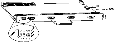
Some interface processors consist of a single motherboard, and others consist of a motherboard with a companion board such as a physical layer interface module (PLIM) or a port adapter. For example, the AIP (see Figure 7-8) contains a PLIM, which determines the type of ATM connection.

Interface processors such as the FSIP, FEIP, or VIP2 contain port adapters that attach to the motherboard. Figure 7-9 shows a VIP2 with two different port adapters.
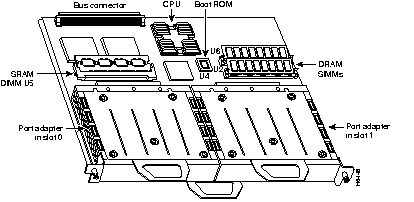
The factory installs PLIM and port adapter configurations according to the interface processor ordered.
The following sections list and describe the interface processors available for the Cisco 7000 series and Cisco 7500 series routers.
The AIP (see Figure 7-10) provides a native ATM interface for the Cisco 7000. The AIP is available with one port, and it can be ordered to support one of the following media:
The ATM cable connects to a PLIM on the AIP card (see Figure 7-8). The module supplies the interface type and can be ordered as a spare.
The AIP is compatible with a wide range of ATM devices, for example, the LightStream 1010 ATM switch, the Catalyst 5000 LAN switch equipped with an ATM LAN Emulation module, Cisco 4000 series routers (models 4500 and 4500-M) with an ATM Network Processor module, ATM SBus adapter, and ATM switches from other vendors.
For cable and connector information about the AIP, see the "ATM Cable Specifications" section in the "Cables and Transceivers" chapter later in the catalog.
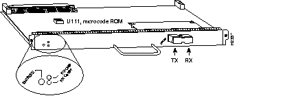
The ATM Cable Interface Processor (ACIP) (see Figure 7-11) provides a single, full-duplex, ATM network interface for a Cisco 7500 series router by providing a direct connection between the router's high-speed Cisco Extended Bus (CyBus) and external equipment. The ACIP can be connected directly to a Cisco Lightstream 1010 ATM switch or other external ATM network equipment, and to cable television (CATV) equipment, such as the Terayon TeraLink 1000 cable head end. A physical layer interface module (PLIM) on the ACIP provides a SONET/SDH (STS-3C) multimode interface connection.
The ACIP supports the following features:
For cable and connector information about the ACIP, see the "ATM Cable Specifications" section in the "Cables and Transceivers" chapter later in the catalog.

The second-generation CIP2 (see Figure 7-12) provides a connection to IBM or IBM-compatible mainframes. It supports both IBM mainframe cabling standards: parallel channel (also called bus and tag) and ESCON architecture. To operate with the CIP2, Cisco 7000 series systems require Cisco IOS Release 10.2(13) or later, Release 10.3(13) or later, Release 11.0(10) or later, or Release 11.1(5) or later. Cisco 7500 series systems require Cisco IOS Release 10.3(13) or later, Release 11.0(10) or later, or Release 11.1(5) or later. By default, the CIP2 ships with 32 MB of memory; additional memory is available in 64- and 128-MB sizes. To calculate CIP2 memory requirements, see the "CIP2 Memory Guidelines" section later in this chapter.
Each CIP2 can support up to two IBM mainframe channel connections, which can be one of the following:
Three software features are available for the CIP2: a TCP/IP datagram feature, a TCP/IP offload feature, and an SNA support feature. TPC/IP datagram is a standard feature for the CIP2. TCP/IP offload and SNA support are licensed features and must be ordered separately.
The TCP/IP offload feature places TCP/IP protocols onto the CIP2, where they assume the responsibility of processing TCP/IP frames, calculating the checksum, and retransmitting bad frames. The mainframe TCP/IP stack is still required for the server applications FTP, Telnet, TN3270, NFS, and LPd, but TCP/IP processing is removed from the mainframe and performed on the CIP2. TCP/IP offload is supported only with IBM mainframes.
The SNA support feature delivers SNA traffic to ACF/VTAM using the External Communications Adapter (XCA) major node support provided in ACF/VTAM. The CIP Systems Network Architecture (CSNA) on the CIP2 delivers SNA traffic to and from the mainframe from a variety of sources. Local LANs using SRB, remote LANs using RSRB or DLSw+, APPN, downstream physical unit concentration (DSPU), qualified logical link control (QLLC), source-route translational bridge (SR/TLB), and SDLLC all deliver SNA traffic to the CSNA on the CIP2. Options for the CIP2 are listed in Table 7-45.
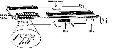
Use Table 7-43 to determine a conservative session capacity for the CIP2 DRAM configurations. If a single feature is being deployed with a single session type, use this table. However, if multiple features are deployed concurrently, use the formulas in Table 7-44.
| Description | Telnet Sessions | Other TCP Sessions | LLC Sessions |
|---|---|---|---|
| CIP2 with 32-MB DRAM | 4,500 | 450 | 2,000 |
| CIP2 with 64-MB DRAM1 | 10,000 | 950 | 4,000 |
| Description | Formula |
|---|---|
| TCP/IP offload feature only | 2.5 MB + (6 KB x number of Telnet sessions) + (64 KB x number of other TCP sessions) |
| CSNA feature only | 5.0 MB + (12 KB x number of LLC sessions) |
| TCP/IP offload and CSNA concurrently | 6.5 MB + (6 KB x number of telnet sessions) + (64 KB x number of other TCP sessions) + (12 KB x number of LLC sessions) |
For example, if you are configuring the memory for the CSNA feature and you are planning to support 1024 LLC connections, the amount of DRAM required is calculated as follows: 
Because the default memory for the CIP2 is 32 MB, you will need to order 32 MB of CIP2 DRAM.
If you are configuring the CIP2 for TCP/IP offload and you are planning to support 2048 Telnet sessions and 256 FTP sessions, then the formula is as follows:
This configuration will also require 32 MB of CIP2 DRAM.
| Description | Product Number |
| 32-MB memory (default CIP2 memory) | MEM-CIP-32M |
| 64-MB memory (replaces existing CIP2 memory) | MEM-CIP-64M(=) |
| 128-MB memory (replaces existing CIP2 memory) | MEM-CIP-128M(=) |
| TCP/IP offload feature for CIP2 (ordered with CIP2) | FR-CIP-TCPOFF |
| TCP/IP offload feature for CIP2 (spare) | FR-CIP-TCPOFF= |
| SNA support feature for CIP2 SNA (ordered with CIP2) | FR-CIP-CSNA |
| SNA support feature for CIP2 SNA (spare) | FR-CIP-CSNA= |
| Downstream bus and tag connection with bus and tag termination | CAB-PCA-VB |
| Upstream bus and tag connection with bus and tag termination1 | CAB-PCA-VA |
| Spare 78-pin D-shell cable for CIP2 | CAB-PCA-Y= |
| Additional ESCON channel adapter for CX-CIP2-PCA1 or CX-CIP2-ECA1 | CX-ECA1-U2 |
The CT3IP (see Figure 7-13) is a fixed-configuration interface processor based on the second-generation Versatile Interface Processor (VIP2). The CT3IP has four T1 connections via DB-15 connectors and one DS-3 connection via BNC connectors. It operates on any Cisco 7500 series router or any Cisco 7000 series router equipped with an RSP7000 processor and an RSP7000CI chassis interface.
Each DS-3 interface can provide up to 28 T1 channels (a single T3 group). Each channel is presented to the system as a serial interface that can be configured individually. The CT3IP can transmit and receive data bidirectionally at the T1 rate of
1.536 Mbps. The individual T1 connections use 100-ohm, twisted-pair, serial cables to external channel service units (CSUs) or to a MultiChannel Interface Processor (MIP) for subsequent channelization to 24 DS0 channels per T1.
For wide-area networking, the CT3IP can function as a concentrator for a remote site. The T3 connection, provided by way of two female BNC connections for transmit (TX) and receive (RX), has an impedance of 75 ohms.
Packet memory for the CT3IP is 1 to 2 MB of SRAM provided on one dual-inline memory module (DIMM). CT3IP microcode is loaded into and operates from DRAM. The DRAM configuration is 16 to 32 MB, and is provided on two single-inline memory modules (SIMMs).
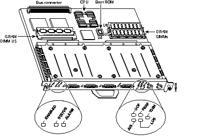
Cisco Systems's channelized digital signal level 3 (DS#) interface processor model 50 is an enhancement to the existing CT3IP-40 for Cisco 7500 and 7000/Route Switch Processor (RSP) series routers. Built on the new VIP2-50 platform, the CT3IP-50 extends the performance and IOS service support of the CT3IP-XX family to greater levels. The CT3IP-50 allows 28 T1 connections to be terminated on a router via a single DS3 connection.
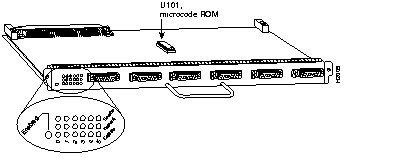
The EIP (see Figure 7-14) provides two, four, or six high-speed (10-Mbps) Ethernet ports. Each port requires a user-supplied 802.3 media attachment unit (MAU) and an AUI cable.
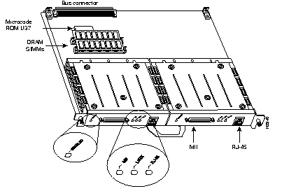
The FEIP (see Figure 7-15) provides one or two Fast Ethernet (100-Mbps) ports, which support twisted-pair or fiber-optic cable. The 100BaseT interfaces are mounted on port adapters that attach to the FEIP motherboard. Each port adapter has two 100BaseT interfaces: one RJ-45 and one MII connection. Only one connection can be used per port adapter.
Each 100BaseT port on the FEIP has an RJ-45 connector to attach to Category 5 UTP for 100BaseTX, and an MII connector that permits, through user-provided transceivers, connection to other physical layers. Only one connector on a Fast Ethernet port adapter can be used at one time. Both full-duplex and half-duplex operations are supported.
The FEIP can operate with a variety of 100BaseFX or 100BaseTX devices, for example, a Catalyst 5000 switch with Fast Ethernet interface modules installed. To support 100BaseTX connections, the host Cisco 7000 series router must be running Cisco IOS Release 10.3(5) or later, and the host Cisco 7500 series routers must be running Cisco IOS Release 10.3(6) or later. To support 100BaseFX connections, the host Cisco 7000 series and Cisco 7500 series router must be running Cisco IOS Release 10.3(13), or later, Release 11.0(10) or later, or Release 11.1(5) or later.
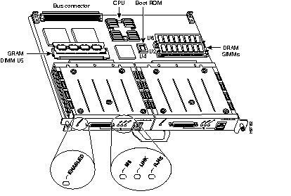
The second-generation Fast Ethernet Interface Processor (FEIP2) (see Figure 7-16) provides one or two Fast Ethernet (100-Mbps) ports, which support twisted-pair or fiber-optic cable. It provides significantly higher throughput characteristics in full-duplex operation than the previous generation FEIP. The 100BaseT interfaces are mounted on port adapters that attach to the FEIP2 motherboard. Each port adapter has two 100BaseT interfaces: one RJ-45 and one MII connection. Only one connection can be used per port adapter.
Each 100BaseT port on the FEIP2 has an RJ-45 connector to attach to Category 5 UTP for 100BaseTX, and an MII connector that permits, through user-provided transceivers, connection to other physical layers. Only one connector on an FE port adapter can be used at one time. Both full-duplex and half-duplex operations are supported on each interface.
The FEIP2 can operate with a variety of 100BaseFX or 100BaseTX devices, for example, a Catalyst 5000 switch with Fast Ethernet interface modules installed. The Cisco 7000 series and Cisco 7500 series router must be running Cisco IOS Release 11.1(10)CA or later. The FEIP2 provides 1 MB of SRAM and 8 MB of DRAM.
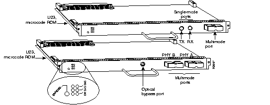
The FIP (see Figure 7-17) provides one high-speed (100-Mbps) FDDI port. Four types of FIPs are available:
The last two letters of the FIP type name indicate the functions of the PHY-A and PHY-B connectors, respectively. Thus, for the CX-FIP-SM (single-mode to multimode) FIP, PHY-A is single-mode, and PHY-B is multimode. For the CX-FIP-MS (multimode to single-mode) FIP, PHY-A is multimode, and PHY-B is single-mode.
The FSIP (see Figure 7-18) provides four or eight high-speed serial ports (up to 6.132 Mbps). Each FSIP comes with a default dual-port port adapter, PA-7KF-SPA, as follows:
For G.703/G.704 support, you must order port adapters PA-7KF-E1/120= or PA-7KF-E1/75=. The G.703/G.704 cables must match the ohm rating for the port adapters. For example, PA-7KF-EI/75, the 75-ohm port adapter, uses the G.703/G.704 75-ohm cable, CAB-E1-BNC.
Except for G.703/G.704 port adapters, the cable connected to the port determines the interface type and mode. Table 7-49 lists Cisco 7000 series and Cisco 7500 series serial cables supported by the FSIP. These cables must be ordered with the FSIP.
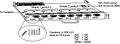
The HIP (see Figure 7-19) provides one HSSI (up to 52-Mbps) port. This port allows you to choose from a range of connectivity options, including ATM, SMDS, Frame Relay, or private lines--all at speeds up to DS-3 or E3 (45 Mbps and 34 Mbps, respectively). Only a software configuration is necessary to accommodate these different network connections.
An HSSI cable is required for each HIP. All cables are 10 feet (3 meters) long and must be ordered with the HIP. For cable part numbers, see Table 7-49.
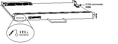
Seven models of the MIP (see Figure 7-20) provide a multichannel multiplexer that allows aggregate multiple channels at Nx64 and/or Nx56 on the same 1.5-Mbps T1 line. Models CX-MIP-1CT1 and CX-MIP-2CT1 provide one or two T1/PRI ports. Cables must be ordered with the MIP. See Table 7-49 for cable product numbers.
When used with Cisco IOS dial-on-demand routing software, the MIP can operate as a single- or dual-port ISDN PRI device. A dual-port MIP card can be configured to allow one port to operate as an ISDN PRI while the other performs a multichannel multiplexer role.

The POSIP (Packet OC-3 Interface Processor) (see Figure 7-21) provides a single 155.520-Mbps, OC-3 single-mode or multimode fiber-optical network interface for Cisco 7000 series and 7500 series routers. It operates on any Cisco 7500 series router or any Cisco 7000 series router equipped with an RSP7000 processor.
Packet data is transported using Point-to-Point Protocol (PPP) and is mapped into the STS-3c/STM-1 frame. The Packet OC-3 interface is compliant with RFC 1619, "PPP over SONET/SDH," and RFC 1662, "PPP in HDLC-like Framing." The encapsulations used add approximately half of the number of bytes of transport overhead as that involved with ATM using ATM adaptation Layer 5 (AAL5) and line card control (LCC) Subnetwork Access Protocol (SNAP) encapsulations.
The POSIP comes configured with 32 MB of DRAM and 2 MB of SRAM as the factory default memory configurations.
The network interfaces reside on the POSIP and provide a direct connection between the high-speed Cisco Extended Bus (CxBus or CyBus) and external networks. The physical layer interface on the POSIP is OC-3. There are no restrictions on slot locations or sequence; you can install a POSIP in any available interface processor slot.
The POSIP supports the following features:
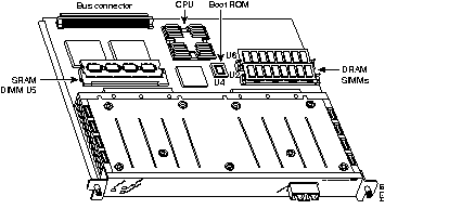
The SMIP (see Figure 7-22) has two channelized T1 or two channelized E1 connections via serial cables to a CSU. Two controllers can each provide up to 24 T1 channel groups or 30 E1 channel groups. Each channel group is presented to the system as a serial interface that can be configured individually.
The SMIP provide a multichannel multiplexer that allows aggregate multiple channels at Nx64 and/or Nx56 on the same 1.5-Mbps T1 line. Cables must be ordered with the SMIP. See Table 7-49 for cable product numbers.
The SMIP has one or two controllers for transmitting and receiving data bidirectionally at the T1 rate of 1.544 Mbps. For wide-area networking, the SMIP can function as a concentrator for a remote site.
Cisco IOS Release 10.3(6) or later supports the SMIP, which is licensed to support the following:
The SMIP does not support multiprotocol routing.

The SSIP (see Figure 7-23) provides eight high-speed serial ports (up to 8 Mbps).
The CX-SSIP8 comes with four dual-port port adapters (PA-7KF-SPA), which can support X.21, EIA/TIA-449, EIA/TIA-232, V.35, or EIA-530.
For G.703/G.704 support, you must order port adapters PA-7KF-E1/120= or PA-7KF-E1/75=. The G.703/G.704 cables must match the ohm rating for the port adapters. For example, PA-7KF-EI/75, the 75-ohm port adapter, uses the G.703/G.704 75-ohm cable, CAB-E1-BNC.
Except for G.703/G.704 port adapters, the cable connected to the port determines the interface type and mode. Table 7-49 lists Cisco 7000 series and Cisco 7500 series serial cables supported by the SSIP. These cables must be ordered with the SSIP.
Cisco IOS Release 10.3(6) or later supports the SSIP. The SSIP is licensed to support the following:
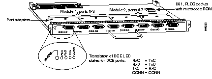
The TRIP (see Figure 7-24) provides two or four high-speed (4-Mbps or 16-Mbps) Token Ring ports. Each port requires a MAU to connect the DB-9 connector to the external Token Ring networks.
The second-generation Versatile Interface Processor (VIP2) is used with the Cisco 7000 series routers using the RSP7000 and RSP7000CI, and the Cisco 7500 series routers.
The VIP2 installs in the interface processor slots in your Cisco 7000 series or Cisco 7500 series router, and requires that the Cisco 7000 series router has the 7000 Series Route Switch Processor (RSP7000) and RSP7000CI installed. The VIP2 uses a single motherboard with up to two port adapters or service adapters. The VIP2 port adapters provide the individual LAN and WAN interface ports.
The VIP2-15 provides for high-density, mixed-media support of a variety of port and service adapters. Packets are forwarded to the Route Switch Processor for processing. The VIP2-40 builds on the capabilities of the VIP2-15 with support for distributed switching and distributed services. Distributed switching allows the VIP2-40 to perform layer 3 switching services for the local port adapters. Distributed services enable advanced Cisco IOS layer 3 services such as encryption and compression to be processed on the VIP, thus relieving the main Route Switch Processor from these activities.
The VIP2 can be removed from a chassis while power is on and the system is operating. There are no restrictions on the chassis interface processor slots in which the VIP2 can be installed.
The VIP2 CPU is an RISC, MIPS 4700 processor that has an internal operating frequency of 100 MHz and a 50 MHz system bus interface. The VIP2 has 128 KB of nonvolatile random-access memory (NVRAM).
Table 7-46 shows the DRAM, SRAM, and software capabilities of the current VIP2 products.
| VIP2 Model | Distributed Switching | Distributed Services | DRAM | SRAM |
|---|---|---|---|---|
| VIP2-101 | - | - | 8 MB | 512 KB |
| VIP2-15 | - | - | 8 MB | 1 MB |
| VIP2-201 | Y | - | 16 MB | 1 MB |
| VIP2-40 | Y | Y | 32 MB | 2 MB |
The VIP2-10, VIP2-15, and VIP2-20 can support the following SRAM, DRAM, and software memory-configuration upgrades:
The VIP2 provides support for any two port adapters as listed in Table 7-47.
When you order a VIP2, memory and software are important considerations. Use the following information when ordering a VIP2:
Figure 7-25 shows a VIP2 board with one PA-FE-TX port adapter and a blank port adapter installed. The port adapter handles have been omitted for clarity.
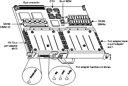
Table 7-47 outlines the minimum VIP2 hardware configurations for port adapters supported by the VIP2 architecture.
| Slot 1 | |||||||||
|---|---|---|---|---|---|---|---|---|---|
| Blank or Ethernet 8E | Ethernet 4E or 5EFL | Ethernet FE-TX or FE-FX | Token Ring 4R 1 | Serial 4T | Serial 8T | HSSI | FDDI F and F/FD2 | Comp/1 or Comp/4 Service Adapter | |
| Slot 0 | |||||||||
| Blank | VIP2-10 | VIP2-10 | VIP2-10 | VIP2-15 | VIP2-10 | VIP2-10 | VIP2-15 | VIP2-15 | VIP2-40 |
| Ethernet 8E | VIP2-10 | VIP2-10 | VIP2-10 | VIP2-15 | VIP2-10 | VIP2-15 | VIP2-15 | VIP2-15 | VIP2-40 |
| Ethernet 4E | VIP2-10 | VIP2-10 | VIP2-10 | VIP2-15 | VIP2-10 | VIP2-10 | VIP2-15 | VIP2-15 | VIP2-40 |
| Ethernet 5EFL | VIP2-10 | VIP2-10 | VIP2-10 | VIP2-15 | VIP2-10 | VIP2-15 | VIP2-15 | VIP2-15 | VIP2-40 |
| Ethernet FE-TX | VIP2-10 | VIP2-10 | VIP2-10 | VIP2-15 | VIP2-10 | VIP2-10 | VIP2-15 | VIP2-15 | VIP2-40 |
| Ethernet FE-FX | VIP2-10 | VIP2-10 | VIP2-10 | VIP2-15 | VIP2-10 | VIP2-10 | VIP2-15 | VIP2-15 | VIP2-40 |
| Token Ring 4R | VIP2-15 | VIP2-15 | VIP2-15 | VIP2-15 | VIP2-15 | VIP2-15 | VIP2-15 | VIP2-15 | VIP2-40 |
| Serial 4T | VIP2-103 | VIP2-103 | VIP2-103 | VIP2-15 | VIP2-103 | VIP2-15 | VIP2-15 | VIP2-15 | VIP2-40 |
| Serial 8T | VIP2-15 | VIP2-15 | VIP2-15 | VIP2-15 | VIP2-15 | VIP2-15 | VIP2-15 | VIP2-15 | VIP2-40 |
| HSSI | VIP2-15 | VIP2-15 | VIP2-15 | VIP2-15 | VIP2-15 | VIP2-15 | VIP2-15 | VIP2-15 | VIP2-40 |
| FDDI F and F/FD2 | VIP2-15 | VIP2-15 | VIP2-15 | VIP2-15 | VIP2-15 | VIP2-15 | VIP2-15 | VIP2-15 | VIP2-40 |
| Comp/1 or Comp/2 Service Adapter | VIP2-40 | VIP2-40 | VIP2-40 | VIP2-40 | VIP2-40 | VIP2-40 | VIP2-40 | VIP2-40 | VIP2-40 |
Table 7-48 lists the interface processors and options available for the Cisco 7000 series and Cisco 7500 series and provides interface processor product numbers.
| Interface Processor | Description | Product Number |
|---|---|---|
AIP | ATM Interface Processor, 1 TAXI multimode port, 100 Mbps | CX-AIP-TM |
| ATM Interface Processor, 1 SONET/SDH multimode port, 155 Mbps | CX-AIP-SM | |
| ATM Interface Processor, 1 SONET/SDH single-mode port, 155 Mbps | CX-AIP-SS | |
| ATM Interface Processor, 1 E3 coaxial port, 34 Mbps | CX-AIP-E3 | |
| ATM Interface Processor, 1 DS3 coaxial port, 45 Mbps | CX-AIP-DS3 | |
| ACIP | ATM Cable Interface Processor, 1 SONET/SDH multimode port, 155 Mbps | CX-ACIP-SM |
CIP2 | Second-generation Channel Interface Processor with single parallel channel | CX-CIP2-PCA11 |
| Second-generation Channel Interface Processor with dual parallel channel | CX-CIP2-PCA21 | |
| Second-generation Channel Interface Processor with single ESCON channel | CX-CIP2-ECA1 | |
| Second-generation Channel Interface Processor with dual ESCON channel | CX-CIP2-ECA2 | |
| Second-generation Channel Interface Processor with single ESCON channel and single parallel channel | CX-CIP2-ECAP11 | |
CT3IP2 | Channelized T3 Interface Processor, 1 port, 1-MB SRAM, 16-MB DRAM | CT3IP-20 |
| Channelized T3 Interface Processor, 1 port, 2-MB SRAM, 32-MB DRAM | CT3IP-40 | |
CT3IP-50 | Channelized DS3 Interface Processor, Model 50, 4 MB SRAM, 32 MB SDRAM | CT3IP-50 |
| May be ordered with the following memory options: 8 MB SRAM Option for VIP2-50 (Packet Memory) 64 MB SDRAM Option for VIP2-50 (Program Memory) 128 SDRAM Option for VIP2-50 (Program Memory) | MEM-VIP250-8M-S MEM-VIP250-64M-D MEM-VIP250-128M-D | |
EIP3 | Ethernet Interface Processor, 2 ports | CX-EIP2 |
| Ethernet Interface Processor, 4 ports | CX-EIP4 | |
| Ethernet Interface Processor, 6 ports | CX-EIP6 | |
FEIP4 | Fast Ethernet Interface Processor, 1 port | CX-FEIP-1FX |
| Fast Ethernet Interface Processor, 2 ports | CX-FEIP-2FX | |
| Fast Ethernet Interface Processor, 1 port | CX-FEIP-1TX | |
| Fast Ethernet Interface Processor, 2 ports | CX-FEIP-2TX | |
FEIP2 | Second-Generation Fast Ethernet Interface Processor, 2 ports | FEIP2-2TX |
| Second-Generation Fast Ethernet Interface Processor, 2 ports | FEIP2-2FX | |
FIP3 | FDDI Interface Processor, 1 multimode to multimode port5 | CX-FIP-MM |
| FDDI Interface Processor, 1 single-mode to single-mode port | CX-FIP-SS | |
| FDDI Interface Processor, 1 multimode to single-mode port | CX-FIP-MS | |
| FDDI Interface Processor, 1 single-mode to multimode port | CX-FIP-SM | |
| Fast Serial Interface Processor, 4 ports | CX-FSIP4 | |
| FSIP dual-port port adapter, default is 2 | PA-7KF-SPA | |
| FSIP E1-G.703/G.704 120-ohm dual port adapter | PA-7KF-E1/120 | |
| FSIP E1-G.703/G.704 75-ohm dual port adapter | PA-7KF-E1/75 | |
| Fast Serial Interface Processor, 8 ports | CX-FSIP8 | |
| FSIP dual-port port adapter (PA), default is 2 | PA-7KF-SPA | |
| FSIP E1-G.703/G.704 120-ohm dual port adapter | PA-7KF-E1/120 | |
| FSIP E1-G.703/G.704 75-ohm dual port adapter | PA-7KF-E1/75 | |
| HIP7 | HSSI Interface Processor, 1 high-speed serial port | CX-HIP |
MIP8 | MultiChannel Interface Processor, 1-port T1/PRI | CX-MIP-1CT1 |
| MultiChannel Interface Processor, 2-port T1/PRI | CX-MIP-2CT1 | |
POSIP2 | Packet OC-3 Interface Processor, 1 single-mode port, 1-MB SRAM, 16-MB DRAM | POSIP-OC3-20-SM |
| Packet OC-3 Interface Processor, 1 multimode port, 1-MB SRAM, 16-MB DRAM | POSIP-OC3-20-MM | |
| Packet OC-3 Interface Processor, 1 single-mode port, 2-MB SRAM, 32-MB DRAM | POSIP-OC3-40-SM | |
| Packet OC-3 Interface Processor, 1 multimode port, 2-MB SRAM, 32-MB DRAM | POSIP-OC3-40-MM | |
| SMIP8 | Service Provider MultiChannel Interface Processor, 2 T1 or ISDN PRI ports | CX-SMIP-2CT1 |
| SSIP3,6 | Standard Serial Interface Processor, 8-port | CX-SSIP8 |
TRIP | Token Ring Interface Processor, 2-port | CX-TRIP2 |
| Token Ring Interface Processor, 4-port | CX-TRIP4 | |
| VIP2-152 | Second-Generation Versatile Interface Processors, Forwarding Mode Only | See Table 7-46 |
| VIP2-40 | Second-Generation Versatile Interface Processors, Distributed Switching and Services | See Table 7-46 |
| Investment Protection Program (IPP) | Interface processor upgrades | See Table 7-51 |
Table 7-49 lists interface processor cables and provides product numbers. For more information about these cables, refer to the "Cables and Transceivers" chapter.
<$lastpagenum>
| Interface Processor | Cable Description | Product Number |
|---|---|---|
| AIP | - | For DS3/E3, use CAB-ATM-DS3/E3
Other cables are user supplied |
| CIP21,2 | Y cable that comes with CIP2
PCA V cable A PCA V cable B | CAB-PCA-Y
CAB-PCA-VA3 CAB-PC-VB |
| CT3IP | - | User supplied |
| EIP | - | User supplied |
| FEIP | - | User supplied |
| FEIP2 | - | User supplied |
| FIP2 | Mini-DIN-to-DIN transition | CAB-FMDD= |
| FSIP2
SSIP2 VIP-4E/4T2 VIP-4R/4T2 | X.21 high-density male DTE
X.21 high-density female DCE EIA/TIA-449 high-density male DTE EIA/TIA-449 high-density female DCE V.35 high-density male DTE V.35 high-density female DCE EIA/TIA-232 high-density male DTE EIA/TIA-232 high-density female DCE EIA-530 high-density male DTE E1-G.703/G.704 twinax 120-ohm balanced, 16.4 feet E1-G.703/G.704 DB-15 120-ohm balanced, 16.4 feet E1-G.703/G.704 BNC 75-ohm unbalanced, 16.4 feet | CAB-X21MT
CAB-X21FC CAB-449MT CAB-449FC CAB-V35MT CAB-V35FC CAB-232MT CAB-232FC CAB-530MT CAB-EI-TWINAX CAB-EI-DB15 CAB-EI-BNC |
| HIP 4 | Null modem, DTE, HSSI, 10 feet
Male to male, 10 feet | CAB-HNUL=
CAB-HSI1= |
| MIP or SMIP2 | DSX1 to CSU DB-15 thru
DSX1 to CSU DB-15 null E1 ISDN PRI, 10 feet E1 BNC 75-ohm unbalanced, 16.4 feet E1 DB15 120-ohm balanced, 16.4 feet E1 TWINAX 120-ohm balanced, 16.4 feet | CAB-7KCT1DB15
CAB-7KCT1NULL CAB-E1-PRI CAB-E1-BNC CAB-E1-DB15 CAB-E1-TWINAX |
| POSIP | - | User supplied |
| TRIP | - | User supplied |
| VIP2 | - | User supplied--except for the PA-4T and PA-8T port adapters. See Table 7-53 in the "Port Adapters and Service Adapters for the Cisco 7000 Family" chapter for port adapter cables. |
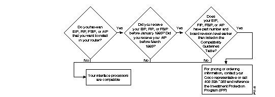
This section describes how to find out if an existing interface processor is compatible with a Cisco 7500 series router or a Cisco 7000 series router upgraded to include an RSP7000. If you determine that you need to upgrade your interface processor, see the "Investment Protection Program" section later in this chapter for more information on Cisco's upgrade program.
To determine compatibility, use the flowchart in Figure 7-26 and the compatibility guidelines in Table 7-50. If you need help in determining a board's part number and revision, see the next section, "Determining Board Part Number and Revision."
| Product Number | Board Part Number1, 2 | Board Revision3, 4 |
|---|---|---|
| CX-AIP-SS | 73-1188-02 | D0 or later |
| CX-AIP-SM | 73-1188-02 | D0 or later |
| CX-AIP-TM | 73-1188-02 | D0 or later |
| CX-AIP-DS3 | - | Does not require an upgrade |
| CX-AIP-E3 | - | Does not require an upgrade |
| CX-EIP2 | 73-1129-02 | N0 or later |
| CX-EIP4 | 73-1132-02 | N0 or later |
| CX-EIP6 | 73-0906-02 | N0 or later |
| CX-FIP-MM | 73-0892-03 | M0 or late |
| CX-FIP-MS | 73-1093-03 | M0 or later |
| CX-FIP-SM | 73-1090-03 | M0 or later |
| CX-FIP-SS | 73-1087-03 | M0 or later |
| CX-FSIP4 | 73-1187-05 | A0 or later |
| CX-FSIP8 | 73-1126-05 | A0 or later |
| All other interface processors5 | - | - |
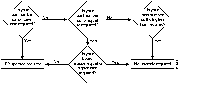
Figure 7-27 provides a flowchart to use with Table 7-50.
You can determine the part number and board revision of your interface processor in one of two ways:
Inspecting the Physical Board
The part number and board revision are typically silk-screened along an edge of the interface processor's printed circuit board:

Using the Show Diagbus Command
You can also use the show diagbus command to determine the part number and board revision of your interface processor. The following is an example of a compatible CX-EIP6:
Router# show diagbus
Slot 0:
Physical slot 0, ~physical slot 0xF, logical slot 0, CBus 0
Microcode Status 0x0
Master Enable, LED, WCS Loaded
Board is analyzed
EEPROM format version 1
EIP controller, HW rev 1.5, board revision B0
Serial number: 01652924 Part number: 73-0906-04
Test history: 0x00        RMA number: 00-00-00
Flags: cisco 7000 board; 7500 compatible
 EEPROM contents (hex):
  0x20: 01 00 01 05 00 19 38 BC 49 03 8A 04 00 00 00 00
  0x30: 58 00 00 00 00 00 00 00 00 00 00 00 00 00 00 00
 Slot database information:
Flags: 0x4      Insertion time: 980 (5d20 ago)
Cisco is committed to protecting your investment in its products. To achieve that, the Cisco 7500 was designed as an extension of the Cisco 7000 platform, allowing you to move existing interface processors between the Cisco 7000 and Cisco 7500 series platforms. However, to ensure forward compatibility with the Cisco 7500 series or a Cisco 7000 series router with an RSP7000 upgrade, some interface processors might need to be modified. The Investment Protection Program (IPP) provides you with a low- or no-cost migration path for upgrading interface processors.
The IPP is intended for the following situations:
The only interface processor types that might require modification are the CX-AIP, CX-EIP, CX-FIP, and CX-FSIP. To verify if one of these processors requires modification, follow the instructions in the "Verifying Interface Processor Compatibility" section earlier in this chapter.
Cisco provides two options for the return and upgrade process:
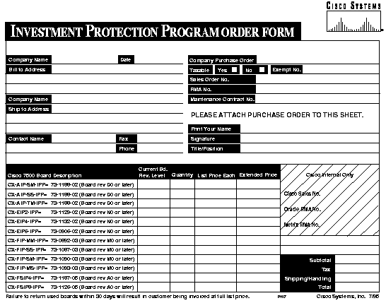
If you determine that your CX-AIP, CX-EIP, CX-FIP, or CX-FSIP needs to be modified, use the product numbers in Table 7-51 and the order form at the end of this chapter.
| Description | Product Number |
|---|---|
| IPP Upgrade ATM Interface Processor with SONET/Multimode | CX-AIP-SM-IPP= |
| IPP Upgrade ATM Interface Processor with SONET/Single-mode | CX-AIP-SS-IPP= |
| IPP Upgrade ATM Interface Processor with TAXI/Multimode | CX-AIP-TM-IPP= |
| IPP Upgrade 2-port Ethernet Interface Processor | CX-EIP2-IPP= |
| IPP Upgrade 4-port Ethernet Interface Processor | CX-EIP4-IPP= |
| IPP Upgrade 6-port Ethernet Interface Processor | CX-EIP6-IPP= |
| IPP Upgrade FDDI Multimode Interface Processor | CX-FIP-MM-IPP= |
| IPP Upgrade FDDI Single-mode Interface Processor | CX-FIP-SS-IPP= |
| IPP Upgrade FDDI Multimode/Single-mode Interface Processor | CX-FIP-MS-IPP= |
| IPP Upgrade FDDI Single-mode/Multimode Interface Processor | CX-FIP-SM-IPP= |
| IPP Upgrade 4-port Fast Serial Interface Processor | CX-FSIP4-IPP= |
| IPP Upgrade 8-port Fast Serial Interface Processor | CX-FSIP8-IPP= |
|
|