Table of Contents
Making Alarm Output Connections
Alarm output connections are made at the DB37 connector on the ARI card. For the connector pin assignments and alarm signal names, see the IPX Reference Manual.
Wire a 22 or 24-gauge cable with the appropriate number of pairs (generally 12 pairs) with a male DB37 connector at one end. Connect this cable to the DB37 connector on the ARI card and tighten the connector captive screws.
Making External Clock Connections
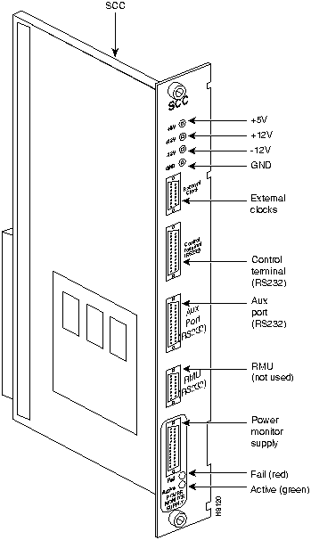
There is a RS-232 connector on the front panel of the SCC and SCC-B for connecting two external sources of a high-stability clock (primary and redundant). These inputs are 1.544 MHz for T1 systems and 2.048 MHz for CEPT systems. A third clock source is the internal IPX clock. One of the packet or circuit line inputs may also be selected for a source of timing for the node. The clock sources PRI, INTC, EXT1 and EXT2 are software selectable through the PCC.
The separate A and B clock inputs are the primary and standby clock sources. Either or both of these can be 1.544 Mbps or 2.048 Mbps. SCC itself selects clock input A or B.
The connector pinouts are described in the IPX Reference Manual.
Attaching Peripherals
To support peripheral attachments, the IPX 16/32 has the two ports CONTROL TERMINAL and AUX PORT on the SCC in back slot 1. A network must have at least one attached control terminal (or StrataView Plus workstation for statistics collecting). A network printer for printing out the state of the system is optional.
For StrataCom ISC to perform remote troubleshooting, the network must have a modem. This is a requirement for all StrataCom service plans.
The sections that follow describe procedures for attaching peripherals to the IPX. Read the manufacturer's literature to ensure the equipment is ready for attachment before you attempt to attach it to the IPX.
Connecting a Network Management Station
At least one node in a IPX network must be connected to a StrataView Plus workstation. The workstation connects to the LAN port (AUI-Ethernet) on the System Clock Card at the rear of the IPX.
StrataView Plus can be used to configure and maintain all IPX nodes in a network. For instructions on using the StrataView Plus workstation, see the StrataView Plus User's Guide.
Figure 2-30 : SCC Connectors

Refer to the IPX Reference Manual for information on control terminals supported by the IPX and their required configuration settings. Refer to the IPX Reference Manual for information on pin assignments for the IPX control terminal port.
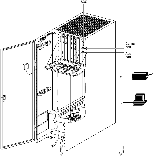
Attach the control terminal (or StrataView Plus workstation) to the IPX as follows (refer to Figure 2-30 and Figure 2-31).
Step 1 For a terminal, from the back of the cabinet, run the control terminal RS-232/V.24 cable through the opening at the bottom and up to the SCC card in back slot 1.
Step 2 For a control terminal, attach the RS-232/V24 cable to the CONTROL TERMINAL connector on the SCC.
Step 3 For a StrataView Plus NMS connection, at the AUI-Ethernet connector on the SCC, attach the AUI and connect to the LAN network.
Figure 2-31 : Connecting the Control Terminal and a Printer

Connecting the Printer
At least one node in the IPX network should have a printer. The printer connects to the AUX PORT on the SCC at back slot 1. The printer is used to display information about network operation. It can be configured to print maintenance information on a regular basis, and it can print specific diagnostic information whenever required. The Command Reference contains instructions for using the printer for this purpose.
Attach the printer to the IPX as follows:
- Check the printer RS-232/V.24 cabling pinout, and if required, adjust the DIP switches to the settings indicated for the type of printer to be connected to the IPX. See Appendix B for RS-232/V.24 cable pinout and DIP switch settings.
- From the back of the cabinet, run the printer RS-232/V.24 cable through the opening at the bottom then up to the SCC card in back slot 1.
- At the AUX PORT connector on the SCC, attach the printer RS-232/V.24 cable.
- Tighten the RS-232/V.24 connector screws to attach the cable connector to the AUX PORT connector.
- Plug the printer power cord into the appropriate wall receptacle.
Connecting a Modem to the IPX
To provide access for remote troubleshooting and remote alarm logging, two modems can be connected to the IPX.
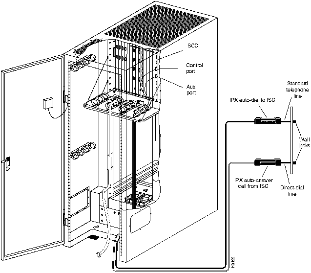
The modem that provides access for remote troubleshooting from the StrataCom ISC office (ISC-to-IPX modem) is connected to the CONTROL TERMINAL port on the SCC at back slot 1. Typically, it connects to the telephone wall jack with a direct-dial line (see Figure 2-32).
The modem that provides remote alarm logging (IPX-to-ISC modem) connects to the AUX PORT on the SCC at back slot 1. This modem connects to a wall jack with a standard telephone cord.
The modem-to-IPX connections require special cables and setup procedures. Refer to the IPX Reference Manual for instructions on connecting and setting up the modem.
Figure 2-32 : Connecting Modems to the IPX

Initial Startup of the IPX
Although the initial startup tasks are similar for the IPX 16/32 and the IPX 8, some differences exist. The two sections that follow explain these differences.
IPX 16/32
Before operating the IPX 16/32, make sure the following procedures have been performed:
Step 1 The IPX cabinet frame is attached to an isolated ground connection.
Step 2 The IPX unit using AC facility power is plugged into an appropriate AC receptacle. The IPX unit using DC facility power is connected to an appropriate dedicated DC source.
Step 3 From the back of the enclosure, turn the power switches to the ON position. The power switches are located on the AC or DC Power Distribution Unit.
Step 4 The power supplies have been checked for correct output.
Step 5 The full complement of cards for the specific node are mounted in the correct slots, correctly seated, and locked.
Step 6 The T1 connections are attached to the appropriate BC-T1 faceplate.
Step 7 The E1 connections are attached to the appropriate BC-E1 faceplate.
Step 8 The Fractional E1 or T1 connections are attached to the BC-E1 or BC-T1 card connector if the IPX is used to provide Fractional E1 or T1 service.
Step 9 The Subrate connections are attached to the BC-SR card connector if the IPX is used to provide Subrate E1 or T1 service.
Step 10 The data connections are attached to the appropriate SDI/LDI cards.
Step 11 The Frame Relay (User Device Connections) are attached to the appropriate FRI card connectors.
Step 12 A control terminal or StrataView Plus workstation can be connected to the SCC. A control terminal is connected to the CONTROL TERMINAL port on the SCC in back slot 1, and the power cord is plugged into the appropriate AC receptacle. If the StrataView Plus NMS is to be connected to the node, it is connected to the AUI-Ethernet connector.
Step 13 If needed, a printer connects to the AUX PORT on the SCC in back slot 1, and its power cord is plugged into the appropriate AC receptacle.
Step 14 If needed, one or more modems connect to the CONTROL TERMINAL port or AUX PORT on the SCC in back slot 1, and each modem power cord is plugged into the appropriate AC receptacle.
Step 15 Observe that, after you turn on the IPX node, the cards go through a series of initial diagnostic self-tests.
- The standby PCC/NPCs red "FAIL" light flashes until self-testing and configuration updates finish. The other NPC becomes active immediately but also performs self-testing and configuration updating. The entire process may take several minutes to complete.
- The remaining cards briefly show "FAIL" then become active or standby.
- The power supplies immediately become "ACTIVE."
- Alarms may be indicated. Alarms may be present on trunks that have not been physically connected. The alarms disappear when you "down" those trunks.
Step 16 If an alarm is present for a T1 or an E1 line that is physically connected to the IPX, try reconnecting the line to make sure there is a good physical connection.
Note If the alarm condition continues, it may indicate a valid T1 or E1 line problem.
IPX 8
Before IPX 8 operation begins, make sure the following procedures have been performed:
Step 1 The IPX cabinet frame is attached to an isolated ground connection.
Step 2 The IPX unit using AC facility power is plugged into an appropriate AC receptacle. Each power supply has its own power cord. The IPX unit using DC facility power is connected to an appropriate dedicated DC source.
Step 3 From the back of the enclosure, turn the power switches to the ON position. The power switches are located on the lower, right, rear of the cabinet.
Step 4 The power supplies have been checked for correct output. The power supply outputs are tested by using the test points on the SCC card.
Step 5 The full complement of cards for the specific node are mounted in the correct slots, correctly seated, and locked.
Step 6 The T1 connections are attached to the appropriate BC-T1 faceplate.
Step 7 The E1 connections are attached to the appropriate BC-E1 faceplate.
Step 8 The Fractional E1 or T1 connections are attached to the BC-E1 or BC-T1 card connector if the IPX is used to provide Fractional E1 or T1 service.
Step 9 The Subrate connections are attached to the BC-SR card connector if the IPX is used to provide Subrate E1 or T1 service.
Step 10 The data cables are attached to the appropriate SDI/LDI cards.
Step 11 The Frame Relay cables (User Device Connections) are attached to the appropriate FRI card connectors.
Step 12 A control terminal or StrataView Plus workstation can be connected to the SCC. A control terminal is connected to the CONTROL TERMINAL port on the SCC in back slot 1, and the power cord is plugged into the appropriate AC receptacle. If the StrataView Plus NMS is to be connected to the node, it is connected to the AUI-Ethernet connector.
Step 13 If needed, a printer connects to the AUX PORT on the SCC in back slot 1, and its power cord is plugged into the appropriate AC receptacle.
Step 14 If needed, one or more modems can connect to the CONTROL TERMINAL port or AUX PORT on the SCC in back slot 1, and each modem power cord is plugged into the appropriate AC receptacle.
Step 15 Observe that, after you turn on the IPX node, the cards go through a series of initial diagnostic self-tests.
- The standby PCC/NPCs red "FAIL" light flashes until self-testing and configuration updates are done. The other PCC becomes active immediately but also performs self-testing and configuration updating. The entire process may take several minutes to complete.
- The remaining cards briefly show "FAIL" then become active or standby.
- The power supplies immediately become "ACTIVE."
- Alarms may be indicated. Alarms may be present on trunks that have not been physically connected. The alarms disappear when you "down" (dnpln) those trunks.
Step 16 If an alarm is present for a T1 or an E1 line that is physically connected to the IPX, try reconnecting the line to make sure the physical connection is a good.
Note If the alarm condition continues, there may be a valid T1 or E1 line problem.
IPX Startup Diagnostic Test
IPX software includes a group of diagnostic tests that run on system hardware at power-up. The startup diagnostic either passes or fails the PCC/NPC(s). Each test result is displayed on the control terminal screen as pass or fail (Figure 2-33 or Figure 2-34).
Figure 2-33 : Power-Up Diagnostic Screen---Passed
**************************************************************************************
Release 8.2 Boot power up diagnostics starting.


Release 8.2 Power up diagnostics complete.
**************************************************************************************
Figure 2-34 : Power-Up Diagnostic Screen---Failed
**************************************************************************************

Release 8.2 Boot power up diagnostics starting.


.
Remove and reinsert this NPC to see if it fails again.
**************************************************************************************
If a NPC fails the power-up diagnostic (Figure 2-34), it does not boot. When this happens, do the following:
Step 1 Remove the failed NPC.
Step 2 Re-install it in the same slot.
Step 3 Wait for the power-up diagnostic to run.
Step 4 If the NPC fails the power-up diagnostics a second time, replace it with another NPC that is known to have passed the test.
Setting Up the IPX Software
The IPX software requires configuration before the IPX can function. Some of the tasks to perform are:
- Configuring Log-On and passwords
- Configuring a network (Node names, Domain Connections, etc.)
- Network synchronization (Clock Sources)
- Third party interfaces
- Connection routing (Bundled Connections, Preferred Routes, etc.)
- Job control information
- Configure Connections (Voice, Low/High Speed Data, Frame Relay, etc.)
For details of IPX commands and usage, refer to the Command Reference Manual.
Checking the IPX Operation
After the IPX is powered up, inspect the status lights on the front cards, back cards, and power supplies. Measure the power supply voltages and replace any power supplies that are out of tolerance.
Table 2-1 shows the normal status of each light, assuming n+1 redundancy for NTC and CDP cards
Table 2-1 : Component Status after Power-Up
| NPC
|
1
|
1
|
---
|
| CDP
|
---
|
---
|
---
|
| NTC
|
---
|
all
|
---
|
| BC-T1/E1
|
---
|
all
|
---
|
| BC-SR (Subrate)
|
---
|
all
|
---
|
| AIT-BC-T3/E3
|
---
|
all
|
---
|
| SDP/LDP
|
---
|
all
|
---
|
| SDI/LDI
|
---
|
all
|
---
|
| FRP
|
---
|
all
|
---
|
| FTC
|
|
|
|
| SCC (A or B)
|
1
|
0
|
---
|
| LEC
|
1
|
0
|
---
|
| ATMT
|
---
|
all
|
|
| ARC
|
1
|
--
|
--
|
| Power Supplies
|
All
|
---
|
---
|
1 Standby status is indicated by no lights on.
- If any card FAIL light is on steady, or if there is no ACTIVE card when there should be for that type, try removing and inserting the same card. Also, check the EEPROMs on the card to make sure they are seated properly.
- If a power supply FAIL light is on, or if no light is on, try removing and inserting the power supply. A failed power supply could also result from incorrect voltage settings.
Checking Power Supply Voltages
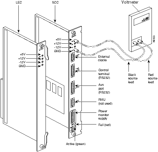
The measuring points for the power supply voltages for a one-shelf system are on the SCC (Figure 2-35). Measuring points for an IPX 32 system are provided on both the SCC and the LEC. Measuring points for the IPX 8 system are provided on the SCC. To measure the power supply outputs, do the following:
Step 1 Set the voltmeter for 20 VDC scale or lowest range applicable to the measurement.
Step 2 Locate the voltage test points on the SCC at back slot 1 (Figure 2-35).
Step 3 To check the +5 VDC power output, touch the voltmeter's black ground lead to GND test point, and touch the red source lead to the +5 VDC test point. The voltmeter should read 5 ± 0.25 VDC.
Step 4 Keep the black ground lead on GND test point. Touch the red source lead to the +12 VDC test point. The voltmeter should read +12 ± 0.5 VDC.
Step 5 Keep the black ground lead on GND test point. Touch the red source lead to the 12 VDC test point. The voltmeter should read --12 ± 0.5 VDC.
Step 6 For the two-shelf system, locate the test points on the LEC card at back slot 17 and repeat the three preceding measurements on the LEC.
Figure 2-35 : Power Supply Voltage Measurement Points

Power supplies are not field-adjustable. If the power supply voltage is out of tolerance, remove and replace with one known to be within tolerance.
Copyright 1988-1996 © Cisco Systems Inc.


![]()
![]()
![]()
![]()
![]()
![]()
![]()
![]()