|
|
Cabling and Pinout Information
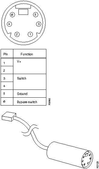
This appendix contains pinout information for CDDI A/B ports, CDDI adapter ports, concentrator master ports, and the optical bypass switch connector.
MLT-3 is the new American National Standards Institute (ANSI) draft specification developed by Cisco Systems for compression of FDDI signals over UTP copper wire. Cisco Systems products that are upgraded to MLT-3 will interoperate with other vendors' equipment that complies with the draft standard.
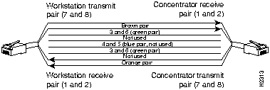
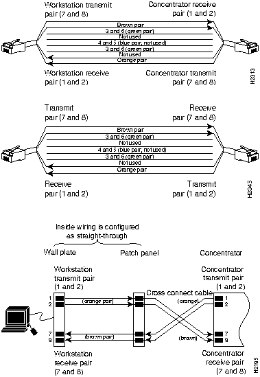
Workgroup CDDI/MLT-3 installations require category 5 equipment throughout. Two types of category 5 modular cables---cross-connect and straight-through---are used to connect concentrators and adapters to the network. (See Figure E-1 and Figure E-2.)
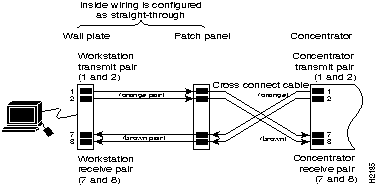
Figure E-1, Figure E-2, and Figure E-3, illustrate the EIA/TIA-568B wiring standard and CDDI transmit and receive pairs
Figure E-1 : Cross-Connect Cable Pinout Figure E-2 : Straight-Through Cable Pinout Figure E-3 : Patch-Panel Connections
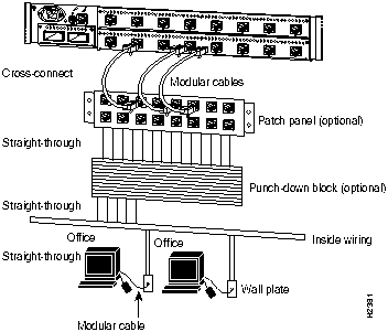
Figure E-4 shows the location of straight-through and cross-connect cabling for CDDI installations. Note that the cross-connect cabling is used between the concentrator and the patch panel.
Figure E-4 : Straight-Through and Cross-Connect Cabling Figure E-5 shows the optical bypass switch connector pinouts.
Figure E-5 : Bypass Connector Pinouts
Copyright 1988-1996 © Cisco Systems Inc.
![]()
![]()
![]()
![]()
![]()
![]()
![]()
![]()