
Table of Contents
Cisco 7513 Card Cage and Backplane Assembly Replacement Instructions
Cisco 7513 Card Cage and Backplane Assembly Replacement Instructions
Product Number MAS-7513CDCAGE=
The card cage and backplane assembly for the Cisco 7513 chassis can be replaced in the field.
Note The card cage and backplane assembly is a single field-replaceable unit (FRU) that requires replacement by a Cisco-certified service provider only. This document assumes you have already performed troubleshooting on your chassis and system; therefore, this replacement procedure is indicated.
This document discusses the procedures required to replace the card cage assembly, and includes the following sections:
Caution Before replacing the card cage and backplane assembly, read the section "Safety Guidelines" on page 3. The specific procedures for removing and installing the card cage and backplane assembly might require two people to perform.
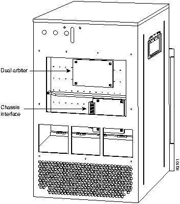
The Cisco 7513 card cage holds the processor modules used by the system. The Cisco 7513 is shown in Figure 1. The card cage and backplane are one assembly that includes the card cage, backplane, dual arbiter, and the chassis interface. The latter two components are printed circuit boards, which are attached to the rear of the backplane. The dual arbiter and chassis interface are replaced when the card cage and backplane assembly is replaced.
Figure 1 Cisco 7513---Rear-Panel View
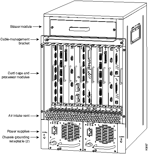
Figure 2 shows the location of the dual arbiter and chassis interface on the rear of the backplane.
Figure 2 Location of the Dual Arbiter and Chassis Interface on the Rear of the Backplane
Before you begin replacing the backplane and card cage assembly, review the safety guidelines in this section to avoid injuring yourself or damaging the equipment. This section also lists of the tools and parts you need to perform this procedure.
The following guidelines will help to ensure your safety and protect the equipment. This list is not inclusive of all potentially hazardous situations, so be alert.
- Never try to lift the chassis by yourself; two people are required to lift the Cisco 7513.
- Always disconnect all power cords and interface cables before moving the chassis.
- Keep tools and chassis components away from walk areas.
- Do not work alone if potentially hazardous conditions exist.
- Do not perform any action that creates a potential hazard to people or makes the equipment unsafe.
- Carefully examine your work area for possible hazards such as moist floors, ungrounded power extension cables, and missing safety grounds.
Follow these basic guidelines when working with any electrical equipment:
- Before beginning any procedures requiring access to the chassis interior, locate the emergency power-off switch for the room in which you are working.
- Disconnect all power and external cables before moving a chassis.
- Do not work alone if potentially hazardous conditions exist.
- Never assume that power is disconnected from a circuit; always check.
- Do not perform any action that creates a potential hazard to people or makes the equipment unsafe.
- Carefully examine your work area for possible hazards such as moist floors, ungrounded power extension cables, and missing safety grounds.
In addition, use the guidelines that follow when working with any equipment that is connected to telephone wiring or other network cabling:
- Never install telephone wiring during a lightning storm.
- Never install telephone jacks in wet locations unless the jack is specifically designed for wet locations.
- Never touch uninsulated telephone wires or terminals unless the telephone line is disconnected at the network interface.
- Use caution when installing or modifying telephone lines.
Electrostatic discharge (ESD) damage, which can occur when electronic boards or components are handled improperly, can result in complete or intermittent failures.
Following are guidelines for preventing ESD damage:
- Always use an ESD-preventive wrist strap or ankle strap and ensure that it makes good skin contact.
- When removing or installing an ESD sensitive component, connect the equipment end of a ground strap to an unpainted surface of the chassis, such as the chassis frame.
- If you are returning a replaced part to the factory, immediately place it in a static shielding bag to avoid ESD damage to the board.
- The wrist strap only protects the board from ESD voltages on the body; ESD voltages on clothing can still cause damage.

Warning For safety, periodically check the resistance value of the antistatic strap. The measurement should be between 1 and 10 megohms.
You need the following tools to install or replace backplane and card cage assembly:
- A 1/4-inch flat-blade screwdriver to loosen the captive screws on the power supplies and card cage
- You will need a number 1 Phillips or 1/4-inch flat-blade screwdriver to remove any blank processor module carriers (fillers) and to tighten the captive installation screws that secure the processor module in its slot.
- Spare card cage assembly---includes the card cage with the chassis interface (attached) and dual arbiter (attached)
- ESD-preventive wrist strap.
- Antistatic packaging in which the old card cage assembly should be placed
Replacing the card cage and backplane assembly first requires you to remove all processor modules installed in the card cage, and then replace them after the new card cage assembly is in place. The term processor module refers to the RSP2 and all interface processors.
Note Always use the ejector levers when installing or removing processor modules. A module that is partially seated in the backplane will cause the system to hang and subsequently crash.
 Timesaver To save time when you reinstall the processor modules in the card cage and reconnect interface cables, use the port and slot worksheet in Table 1 to note which cables are connected to which interface processor ports. (Also refer to Figure 10.)
 Timesaver Before you can remove the card cage and backplane assembly, you must remove all processor modules and both power supplies. Plan this procedure so that you can minimize its effects on your system.
To remove a processor module, follow these steps:
- Step 1 Turn OFF power to the chassis. If two power supplies are installed, the power switch on each supply must be in the OFF (O) position.
- Step 2 Attach an ESD-preventive strap between you and an unpainted surface on the chassis.
- Step 3 If there is not enough slack in the network interface cables to remove the processor module without straining the cables, disconnect any cables attached to the interface ports.
- Step 4 You must pull each processor modules straight out of its slot. Ensure that there are no obstructions that will prevent you from doing so, such as a power strip on a rack post, network connection devices attached to adjacent processor modules, or extensive cabling in front of the processor slots.
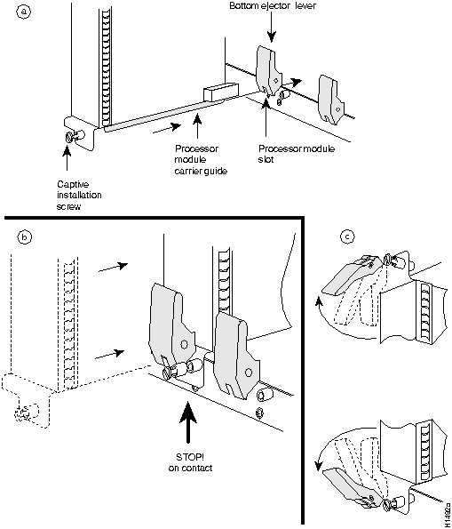
- Step 5 Use a screwdriver to loosen the captive installation screws at the both ends of the processor module. (See Figure 3a.)
- Step 6 Place your thumbs on the ejector levers on both ends of the processor module (see Figure 3c) and simultaneously pull them both outward to release the processor module from the backplane connector.
- Step 7 Grasp the processor module handle with one hand and place your other hand under the carrier to support it. Pull the processor module straight out of the slot keeping it at a 90-degree orientation to the backplane. (See Figure 5 on page 8.)
Figure 3 Ejector Levers and Captive Installation Screws
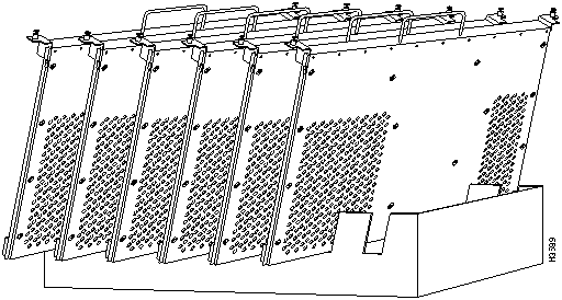
- Step 8 Place the removed processor modules in the black cardboard, board racks that were provided with the original equipment packaging. (See Figure 4.) You can place all 13 processor modules in these holders.
Figure 4 Board Rack with Processor Modules

Caution To prevent damage to the processor modules, do not stack them one on top of another.
You can replace an interface processor in any of the eleven interface processor slots, numbered 0 through 5 (CyBus 0) and 8 through 12 (CyBus 1), from left to right, viewing the chassis from the interface processor end. (See Figure 1.) Slot 6 or 7 can contain the RSP2. Blank processor module fillers are installed in slots without processor modules to maintain consistent air flow through the card cage.
Figure 5 Handling a Processor Module during Installation
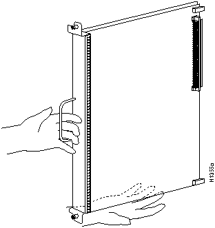

Caution Handle processor modules by the handles and carrier edges only to prevent ESD damage.
To replace a processor module, follow these steps:
- Step 1 Turn OFF power to the chassis. If two power supplies are installed, the power switch on each supply must be in the OFF (O) position.
- Step 2 Processor modules are secured with two captive installation screws. Use a number 1 Phillips or a 1/4-inch flat-blade screwdriver to loosen the two captive installation screws and remove the processor module filler (or the existing processor module) from the slot to be filled.
- Step 3 Hold the processor module handle with one hand, and place your other hand under the carrier to support it. (See Figure 5.) Avoid touching the board.
- Step 4 Place the back of the processor module in the slot and align the carrier guides along the sides of the processor module with the grooves in the top and bottom of the slot. (See Figure 3a.)
- Step 5 While keeping the processor module at a 90-degree orientation to the backplane, carefully slide the processor module into the slot until the processor module faceplate makes contact with the ejector levers.
- Step 6 Using your thumbs, simultaneously push both ejector levers inward until they push the processor module completely into the slot. The ejector levers should be in approximately the same orientation as the processor module faceplate. (See Figure 3c.)
 Caution Always install blank processor module fillers in empty processor slots to maintain the proper flow of cooling air through the chassis.
- Step 7 Use a screwdriver to tighten both captive installation screws on each processor module.
- Step 8 Attach network interface cables or other devices to the interface ports. Use the notes you made in the slot and port worksheet in Table 1.
- Step 9 After you reconnect power and turn ON power, check the status of the interfaces as follows:
- Use the show interface [type] or show controller [type] command to verify that the system has acknowledged the interfaces and brought them up.
- Use the configure command or the setup command facility to configure any new interface(s) you might have installed. This does not have to be done immediately, but the interfaces will not be available until you configure them.
Replacing the card cage and backplane assembly first requires you to remove power supplies (and the power supply blank if one is installed, in a system with one power supply), and then replace them after the new card cage assembly is in place.
Follow these steps to remove a power supply.
- Step 1 Turn OFF (O) the system power switch on each power supply you plan to remove.
- Step 2 Disconnect the power supply cables from the power supplies.
- For DC-input power supplies, refer to the configuration note "1200-Watt DC-Input Power Supply Replacement Instructions" (Document Number 78-1899-01) that shipped with the Cisco 7513 chassis equipped with DC-input power supplies.
- For AC-input power supplies, refer to the configuration note "1200-Watt AC-Input Power Supply Replacement Instructions" (Document Number 78-1900-01) that shipped with the Cisco 7513 chassis equipped with AC-input power supplies.
- Step 3 Use a large slotted screwdriver to loosen the captive screw that secures the power supply to the chassis frame. (See Figure 6.)
Figure 6 Removing a Power Supply (AC-Input Power Supplies Shown)
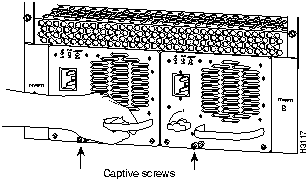
- Step 4 Grasp the power supply handle and pull the power supply about halfway out of the bay, then with your other hand under the power supply, pull it completely out of the bay. (See Figure 7.)
Figure 7 Supporting the Power Supply (AC-Input Power Supply Shown)
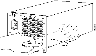

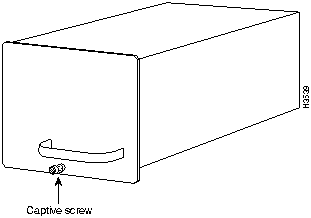
Caution To maintain agency compliance requirements and meet EMI emissions standards in Cisco 7513 chassis with a single power supply, the power supply blank must remain in the power supply bay adjacent to the power supply. (See Figure 8.) Replace this blank in the chassis after you replace the card cage assembly. To prevent system problems, do not mix AC-input and DC-input power supplies in the same chassis.
Figure 8 Power Supply Blank
This completes the power supply removal procedure.
The card cage and backplane consist of one assembly that can be removed and replaced as required. There are no wires, harnesses, or connectors. The assembly slides into and out of the chassis and attaches to the chassis frame with four slotted, captive screws. (See Figure 9.)
For this procedure, you will need one large flat-blade screwdriver, an antistatic bag for each removed processor module, or several antistatic mats or pieces of antistatic foam.

Timesaver Before you can remove the card cage and backplane assembly, you must remove all processor modules and both power supplies. Plan this procedure so that you can minimize its effects on your system.
Following is the procedure to replace the card cage and backplane assembly:
- Step 1 Turn the power switch on each power supply to the OFF position (O).
- Step 2 Disconnect the power supplies.
- For DC-input power supplies, refer to the configuration note "1200-Watt DC-Input Power Supply Replacement Instructions" (Document Number 78-1899-01) that shipped with the Cisco 7513 chassis equipped with DC-input power supplies.
- For AC-input power supplies, refer to the configuration note "1200-Watt AC-Input Power Supply Replacement Instructions" (Document Number 78-1900-01) that shipped with the Cisco 7513 chassis equipped with AC-input power supplies.
- Step 3 Using the directions in the appropriate configuration note, remove each power supply and set it aside. (Refer to the section "Removing a Power Supply" on page 9.)
- Step 4 Remove all processor modules from the chassis and carefully store them in antistatic bags or on an antistatic mat. (Refer to the section "Removing Processor Modules" on page 5.) Do not stack the processor modules one on top of another.
- Step 5 With the processor modules and power supplies removed, loosen the four large captive screws located to the left and right of the card cage opening. (See Figure 9.)
 Caution Unless the chassis is mounted in a rack, or otherwise anchored, the chassis might move toward you when you pull out the card cage and backplane assembly. To prevent injury, have a second person hold the chassis in place while you pull the card cage and backplane assembly from the chassis in the following step.
- Step 6 With the captive screws loosened, carefully pull the card cage and backplane assembly straight out of the chassis until the entire assembly is clear of the chassis sides. (See Figure 9.) The assembly is not heavy, but might be awkward to handle.
- Step 7 When the card cage and backplane assembly is completely free of the chassis, carefully place it on an antistatic mat or foam.
 Caution The electronic components on the rear of the backplane are completely exposed when the card cage and backplane assembly is removed from the chassis. To prevent damaging these components, place the card cage and backplane assembly on an antistatic mat or foam, and place the assembly in the same orientation as when it is mounted in the chassis. (See Figure 9.)
Figure 9 Removing and Replacing the Card Cage and Backplane Assembly
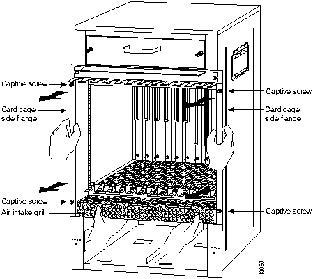
- Step 8 To replace the card cage and backplane assembly, carefully lift the assembly, place it into the chassis opening, and slide the assembly into the chassis opening until the left and right flanges on the card cage are flush with the chassis flanges.
- Step 9 Squeeze the card cage and chassis flanges together and tighten each captive screw. (See Figure 9.) Do not overtighten the captive screws.
 Caution The electronic components on the rear of the backplane are completely exposed when the card cage and backplane assembly is removed from the chassis. To prevent damaging these components, carefully slide the assembly into the chassis opening. (See Figure 9.)
- Step 10 Replace the processor modules in the card cage. To do so, refer to the section "Replacing Processor Modules" on page 8.
- Step 11 Reconnect the power supplies.
- For DC-input power supplies, refer to the configuration note "1200-Watt DC-Input Power Supply Replacement Instructions" (Document Number 78-1899-01) that shipped with the Cisco 7513 chassis equipped with DC-input power supplies.
- For AC-input power supplies, refer to the configuration note "1200-Watt AC-Input Power Supply Replacement Instructions" (Document Number 78-1900-01) that shipped with the Cisco 7513 chassis equipped with AC-input power supplies.
This completes the procedure for replacing the card cage and backplane assembly in the Cisco 7513. Proceed to the section "Replacing a Power Supply," which follows.
Follow these steps to replace the power supply:
- Step 1 To replace a power supply, hold it as shown in Figure 7 and slide it into the power supply bay. Push the supply all the way into the chassis until the sides are flush against the chassis frame.
- Step 2 Use a large slotted screwdriver to tighten the captive screw that secures the power supply to the chassis frame. (See Figure 6.)
- Step 3 Reconnect the power supply cables between the power supplies.
- For DC-input power supplies, refer to the configuration note "1200-Watt DC-Input Power Supply Replacement Instructions" (Document Number 78-1899-01) that shipped with the Cisco 7513 chassis equipped with DC-input power supplies.
- For AC-input power supplies, refer to the configuration note "1200-Watt AC-Input Power Supply Replacement Instructions" (Document Number 78-1900-01) that shipped with the Cisco 7513 chassis equipped with AC-input power supplies.
Note After the AC power cable or DC power cable leads are reconnected, reconnect the power cable at the power source.
This completes the power supply replacement procedure.
To complete the installation, perform a final check of all connections, then restart the system. This procedure is not for new systems; perform this procedure only if you have already connected the network interfaces and performed the first-time startup procedures discussed in the Cisco 7513 Hardware Installation and Maintenance publication and the Router Products Getting Started Guide.
Follow these steps to restart the system and verify that the system restarts successfully:
- Step 1 Check the following components to make sure they are secure:
- Processor modules are fully inserted in the slots and all captive screws are tightened.
- Interface cable connections are secured.
- Power supplies are fully inserted in the bays, and the captive screws are tightened.
- Power supply cables are fully connected to the power supplies and the power source, and secured with appropriate strain relief.
- Step 2 Ensure that a console terminal is connected to the RSP2 console port and turned on, or that you have a remote login to the router from another device through a Telnet session. (You will need to check the startup banner and displays to ensure that the system restarts properly and that all the interfaces reinitialize in the proper state.)
- Step 3 When you have checked all of the connection points, turn on the supply in the power A bay by turning its power switch clockwise one-quarter turn. The OK LED on the power supply and the power A LED on the front of the chassis should go on.
- Step 4 After the power supply in bay A is on, turn the second power supply on in bay B, if one is present for redundant power. The OK LED on each power supply and the power A (and B) LEDs on the front of the chassis should go on.
Note If you try to turn on a power supply and the switch resists, the power supply probably is not fully inserted into the bay. Turn the power switch fully counterclockwise (to O), pull the power supply out of the bay about two inches, then push the power supply firmly back into the slot. Do not slam the supply into the slot---doing so can damage the connectors on the supply and the backplane. Tighten the captive installation screw before turning on the switch.
- Step 5 Listen for the system blower. You should hear it start operating immediately.
- Step 6 On the console terminal, verify that the console displays the system banner and that the system and all interfaces initialize successfully. Following is an example of this display.
(display text omitted)
GS Software (RSP-K), Version 10.3(571)
Copyright (c) 1986-1995 by cisco Systems, Inc.
Compiled Wed 10-May-95 25:12
RSP2 (Risc 4600) processor with 16384K bytes of memory.
(display text omitted)
If the power supplies do not start up, or if the system or any interfaces do not initialize properly, refer to the Cisco 7513 Hardware Installation and Maintenance publication for additional information and installation troubleshooting procedures. If necessary, contact a service representative. (See the following section "Cisco Connection Online.")
Figure 10 Slot Numbering (Use with Table 1)
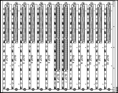
Table 1 Port and Slot Configuration Worksheet (Refer to Figure 10)
| 1 |
|
|
|
|
|
|
|
|
|
|
|
|
|
|
|
|
|
|
|
|
|
|
|
| 2 |
|
|
|
|
|
|
|
|
|
|
|
|
|
|
|
|
|
|
|
|
|
|
|
| 3 |
|
|
|
|
|
|
|
|
|
|
|
|
|
|
|
|
|
|
|
|
|
|
|
| 4 |
|
|
|
|
|
|
|
|
|
|
|
|
|
|
|
|
|
|
|
|
|
|
|
| 5 |
|
|
|
|
|
|
|
|
|
|
|
|
|
|
|
|
|
|
|
|
|
|
|
| 6 |
|
|
|
|
|
|
|
|
|
|
|
|
|
|
|
|
|
|
|
|
|
|
|
| 7 |
|
|
|
|
|
|
|
|
|
|
|
|
|
|
|
|
|
|
|
|
|
|
|
| 8 |
|
|
|
|
|
|
|
|
|
|
|
|
|
|
|
|
|
|
|
|
|
|
|
| Router Name |
Location |
Serial Number |
- (1)
- Slots 6 and 7 are reserved for the RSP2.
Cisco Connection Online (CCO) is Cisco Systems' primary, real-time support channel. Maintenance customers and partners can self-register on CCO to obtain additional content and services.
Available 24 hours a day, 7 days a week, CCO provides a wealth of standard and value-added services to Cisco's customers and business partners. CCO services include product information, software updates, release notes, technical tips, the Bug Navigator, configuration notes, brochures, descriptions of service offerings, and download access to public and authorized files.
CCO serves a wide variety of users through two interfaces that are updated and enhanced simultaneously---a character-based version and a multimedia version that resides on the World Wide Web (WWW). The character-based CCO (called "CCO Classic") supports Zmodem, Kermit, Xmodem, FTP, Internet e-mail, and fax download options, and is excellent for quick access to information over lower bandwidths. The WWW version of CCO provides richly formatted documents with photographs, figures, graphics, and video, as well as hyperlinks to related information.
You can access CCO in the following ways:
- WWW:
http://www.cisco.com
- Telnet:
cio.cisco.com
- Modem: From North America, 408 526-8070; from Europe, 33 1 64 46 40 82. Use the following terminal settings: VT100 emulation; data bits: 8; parity: none; stop bits: 1; and baud rates up to 14.4 kbps.
For a copy of CCO's Frequently Asked Questions (FAQ), contact
ciohelp@cisco.com.
For additional information, contact
cioteam@cisco.com.

Note If you are a network administrator and need personal technical assistance with a Cisco product that is under warranty or covered by a maintenance contract, contact Cisco's Technical Assistance Center (TAC) at 800 553-2447, 408 526-7209, or
tac@cisco.com.
To obtain general information about Cisco Systems, Cisco products, or upgrades, contact 800 553-6387, 408 526-7208, or
csrep@cisco.com.
Copyright 1988-1995
©
Cisco Systems Inc.
![]()


![]()
![]()
![]()


![]()

![]()
![]()


![]()

![]()
![]()
![]()

![]()

