|
|

700-Watt AC-Input Power Supply Installation and Replacement Instructions
Product Numbers: PWR/7-AC and PWR/7-AC=
This document contains instructions for installing or replacing a 700-watt (W), AC-input power supply in the Cisco 7000 and Cisco 7507 chassis.
One 700W power supply is standard equipment in the chassis. A second, identical power supply, when installed, provides redundant power. In systems with redundant power, the power supplies are load-sharing and fully hot-swappable; you can remove and replace one supply, while the remaining supply immediately ramps up to full power to maintain uninterrupted system operation.
The sections in this document include the following:
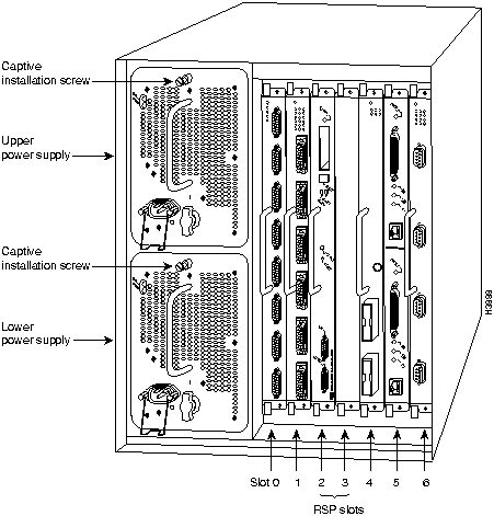
The 700W power supply is a modular power supply for the Cisco 7000 and Cisco 7507 multiprotocol, multimedia routers. One 700W power supply is standard equipment in the chassis. A second, identical power supply, if installed, provides redundant power. Power supplies reside in power supply bays in the rear of the router chassis, as shown in Table 1 on page 4. The lower power supply bay contains the first (standard) power supply, and the upper bay contains the second supply in systems with redundant power. Power supplies reside in power supply bays in the rear of the router chassis, as shown for the Cisco 7000 in Figure 1 and the Cisco 7507 in Figure 2.
Figure 1 AC-Input Power Supplies in the Cisco 7000
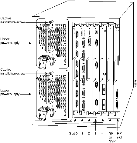
The lower power supply bay contains the first (or standard) power supply, and the upper bay contains the second (optional) supply in systems with redundant power.
Figure 2 AC-Input Power Supplies in the Cisco 7507
![]()
Dual power supplies are automatically load-sharing and redundant, which means that you can install or replace a second power supply on line. During normal operation, dual supplies provide system power simultaneously (load sharing). When you remove one supply, the remaining supply immediately ramps up to provide full power and maintain uninterrupted power to the system. Whenever possible, connect each power supply to a separate AC source. For example, connect one to a standard wall outlet and the other to an uninterruptible power supply (UPS). If there is a power failure, the power supply connected to the UPS maintains uninterrupted system power.
Table 1 lists the chassis power specifications for the AC-input power supply.
Table 1 AC-Input Power Supply Specifications
| Description | Specification |
|---|---|
| Power supply | 700 watts (W) maximum |
| Input voltage | 100 to 240 VAC wide input with power factor corrector (PFC) |
| AC current rating | 12A maximum @ 100 VAC, 6A maximum @ 240 VAC, with chassis fully configured |
| Frequency | 50 to 60 Hz autoranging |
| Power dissipation | 282W minimum configuration626W maximum configuration530W typical with maximum configuration |
| Heat dissipation | 4100 Btu/hr (1200W) |
On the chassis front panel, the upper power and lower power LEDs go on when the power supply in the corresponding bay is installed and supplying power to the system. Both the upper and lower power LEDs should go on in systems with redundant power. In addition to the chassis front panel LEDs, each power supply contains AC power and DC fail LEDs and individual power switches, which are shown in Figure 3.
Figure 3 Power Supply and Status Indicators
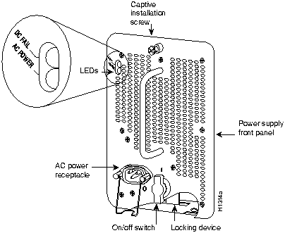
In systems with a single power supply, and in systems with redundant power when both power supplies are shutting down, the DC fail LED goes on momentarily as the system ramps down, but goes out when the power supply has completely shut down. In systems with redundant power and one power supply still active, the DC fail LED on the failed power supply will remain lit (powered by the active supply).
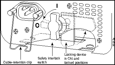
A modular power cord connects each power supply to the site power source. A cable retention clip on the power supply AC receptacle prevents the cable from accidentally being pulled out. The power supplies feature the following three safety interlock features:
Figure 4 Power Supply Safety Interlocks
The power supplies are self-monitoring. Each supply monitors its own temperature and internal voltages. An internal fan in each power supply draws cooling air from the front of the chassis, through the power supply, and out the back of the chassis. An air dam keeps the power supply airflow separate from that of the rest of the chassis (which is cooled by the system blower).
For a complete description of the power supply, refer to the Cisco 7000 Hardware Installation and Maintenance or Cisco 7507 Hardware Installation and Maintenance publications.
Before you begin this installation, review the safety guidelines in this section to avoid injuring yourself or damaging the equipment. This section also provides power requirements to consider if you are adding a second power supply to your system for redundant power, and lists of the tools and parts you need to perform this installation.
![]()
Waarschuwing Dit waarschuwingssymbool betekent gevaar. U verkeert in een situatie die lichamelijk letsel kan veroorzaken. Voordat u aan enige apparatuur gaat werken, dient u zich bewust te zijn van de bij elektrische schakelingen betrokken risico's en dient u op de hoogte te zijn van standaard maatregelen om ongelukken te voorkomen.
Varoitus Tämä varoitusmerkki merkitsee vaaraa. Olet tilanteessa, joka voi johtaa ruumiinvammaan. Ennen kuin työskentelet minkään laitteiston parissa, ota selvää sähkökytkentöihin liittyvistä vaaroista ja tavanomaisista onnettomuuksien ehkäisykeinoista.
Attention Ce symbole d'avertissement indique un danger. Vous vous trouvez dans une situation pouvant causer des blessures ou des dommages corporels. Avant de travailler sur un équipement, soyez conscient des dangers posés par les circuits électriques et familiarisez-vous avec les procédures couramment utilisées pour éviter les accidents.
Warnung Dieses Warnsymbol bedeutet Gefahr. Sie befinden sich in einer Situation, die zu einer Körperverletzung führen könnte. Bevor Sie mit der Arbeit an irgendeinem Gerät beginnen, seien Sie sich der mit elektrischen Stromkreisen verbundenen Gefahren und der Standardpraktiken zur Vermeidung von Unfällen bewußt.
Avvertenza Questo simbolo di avvertenza indica un pericolo. La situazione potrebbe causare infortuni alle persone. Prima di lavorare su qualsiasi apparecchiatura, occorre conoscere i pericoli relativi ai circuiti elettrici ed essere al corrente delle pratiche standard per la prevenzione di incidenti.
Advarsel Dette varselsymbolet betyr fare. Du befinner deg i en situasjon som kan føre til personskade. Før du utfører arbeid på utstyr, må du vare oppmerksom på de faremomentene som elektriske kretser innebærer, samt gjøre deg kjent med vanlig praksis når det gjelder å unngå ulykker.
Aviso Este símbolo de aviso indica perigo. Encontra-se numa situação que lhe poderá causar danos físicos. Antes de começar a trabalhar com qualquer equipamento, familiarize-se com os perigos relacionados com circuitos eléctricos, e com quaisquer práticas comuns que possam prevenir possíveis acidentes.
¡Advertencia! Este símbolo de aviso significa peligro. Existe riesgo para su integridad física. Antes de manipular cualquier equipo, considerar los riesgos que entraña la corriente eléctrica y familiarizarse con los procedimientos estándar de prevención de accidentes.
Varning! Denna varningssymbol signalerar fara. Du befinner dig i en situation som kan leda till personskada. Innan du utför arbete på någon utrustning måste du vara medveten om farorna med elkretsar och känna till vanligt förfarande för att förebygga skador.
The following guidelines will help to ensure your safety and protect the equipment. This list is not inclusive of all potentially hazardous situations, so be alert.
![]()
![]()
![]()
![]()
![]()
This section is only applicable if you do not have clear access to the power supply bays and must move a rack-mounted chassis. If you do have clear access to the power supply bays, proceed to the next section "Safety with Electricity." If space behind a rack-mounted chassis is limited, or if access to the power supply bays is partially blocked by a power strip or other equipment, you may have to slide the chassis partially out of the front of the rack in order to insert the power supplies. At least one person will have to support the front of the chassis while another person pushes it outward from the back and inserts the power supply. If you suspect that pushing the chassis out the front of the rack may topple the rack, make sure enough people are available to support the rack while you perform this procedure. The chassis weighs approximately 120 pounds with 1 power supply and 7 interface processors installed.Whenever you move or lift the chassis or any heavy object, follow these guidelines:
![]()
![]()
You can remove or install a redundant (second) power supply without turning off the other supply. Before removing a redundant power supply, ensure that the first supply is powered on to ensure uninterrupted operation. Follow these basic guidelines when working with any electrical equipment:
In addition, use the guidelines that follow when working with any equipment that is connected to telephone wiring or other network cabling:
The 700W, wide-input power supply uses a power factor corrector (PFC) that allows it to operate on input voltage and current within the ranges of 100--240 VAC and 50--60 Hz. When two power supplies are installed, the redundant power option assures that power to the chassis continues uninterrupted in the event that one power supply fails. It also provides uninterrupted power if an input power line fails only if the power supplies are connected to separate input lines. For maximum reliability, connect one power supply to a standard wall outlet and the other to a separate source, such as an uninterruptible power supply (UPS). If only one input line is available, and you must connect both power supplies to the same source, the redundant power supply will provide continuous power if the first power supply fails. It cannot, however, provide power backup if the input power fails. Table 1 on page 4 lists system power specifications including input voltage and operating frequency ranges.
![]()
This section lists the tools you will need to complete this installation. In most cases, you need only a screwdriver to install or replace a power supply. However, if the chassis is mounted in a rack and access to the power supply bays is partially blocked by a power strip or other equipment, or if you have less than three feet of working space at the rear of the rack, you may need to move the chassis, which requires additional tools.
You need the following tools to install or replace a power supply:
Before beginning the power supply installation, check the installation screws on all power supplies and check the area around the power supply bays to determine which tools you will need.
The new or replacement power supply and the power cord shipped with it are the only parts you need to complete this installation. If you remove a power supply and leave the bay empty, install a cover plate over the empty bay. The chassis is shipped with a cover plate installed over the upper bay. If the plate is not available, contact a service representative to order a replacement (Product Number MAS-7KPSCOVER).
![]()
The following section describes the procedures for removing an existing power supply and installing a new one. It also contains procedures for installing power supplies in rack-mounted chassis when the power supply bays are partially blocked.
If cables from other equipment are in front of the bay, move them aside and temporarily secure them with cable ties. If you must remove a rack-mounted chassis from the rack, proceed to the following section, "Removing a Rack-Mounted Chassis." Otherwise, if you now have clear access to the power supply bays, proceed to the section "Removing a Power Supply" on page 13 to replace an existing supply, or to the section "Inserting a Power Supply" on page 14 to install a new power supply for redundant power.
In systems with redundant power, you can install, remove, or replace one of the power supplies without affecting system operation. When power is removed from one supply, the redundant power feature causes the second supply to ramp up to full power and maintain uninterrupted system operation.
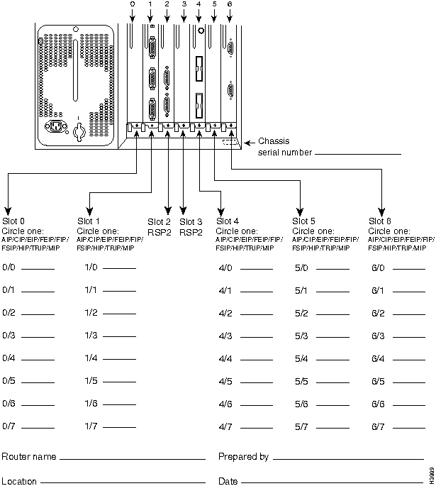
This section describes how to proceed if your system is installed in an equipment rack and you do not have clear access to the power supply bays. If the chassis is not in a rack, or if you already have clear access to the power supply bays, you do not need to perform these steps. Proceed to the sections that follow. If you determine that moving the chassis is unavoidable, you will need to disconnect all power and interface cables. Be sure to label the cables to avoid crossing them when you reconnect them to the chassis. The configuration worksheet provided at the end of this document can help you reconnect the cables to the correct ports if you complete it as you disconnect cables from the interface processors. (For the Cisco 7000, refer to Figure 6, and for the Cisco 7507, refer to Figure 7.)
![]()
To slide the chassis out of the front of the rack to gain access to the power supply bays, do the following:
![]()
![]()
If you are replacing the power supply in a single-supply system, remove the existing supply from the lower bay first, if possible, and install the new power supply in the lower bay to maintain a low center of gravity in the chassis (you will have to interrupt system operation to do so). Always install a filler plate over an empty power supply bay to prevent electrical shock and to protect the backplane connectors from contamination.
Follow these steps to remove a power supply:
![]()
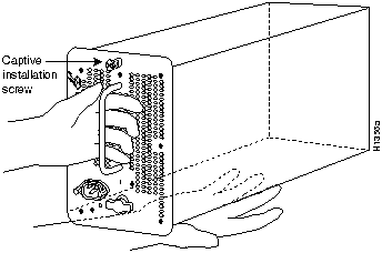
Figure 5 Handling a Power Supply
![]()
If you are installing a replacement power supply, proceed to the next section. Otherwise, reconnect all power and interface cables on the rear of the chassis and restart the system.
Always install the first power supply in the lower power supply bay and the second, if any, in the upper bay. In systems with dual power supplies and when separate power sources are available, connect each power supply to separate input lines, so in case of an input line failure, the second source will most likely still be available.
![]()
![]()
![]()
![]()
To complete the installation you turn the power supply on and observe the LEDs on the power supply to verify that the new supply is operating properly.
If the power supply fails to operate properly after several attempts to initialize it, refer to the note on page 25 of this document and contact a service representative for assistance.
This completes the power supply installation. Refer to the Cisco 7000 Hardware Installation and Maintenance or Cisco 7507 Hardware Installation and Maintenance publications for installation-related troubleshooting procedures, and to the Router Products Configuration Guide publication for descriptions and examples of software features and commands.
Figure 6 Cisco 7000 Port Configuration Worksheet
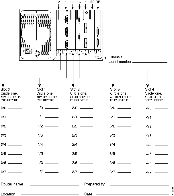
Figure 7 Cisco 7507 Port Configuration Worksheet
Following are translations of the safety warnings that appear throughout this publication:
![]()
Waarschuwing Er zijn twee mensen nodig om het frame op te tillen. Het frame dient onder de onderste rand vastgegrepen en met beide handen omhooggetild te worden. Om te voorkomen dat u letsel oploopt, dient u uw rug recht te houden en met behulp van uw benen, niet uw rug, te tillen. Om schade aan het frame en de onderdelen te voorkomen, mag u nooit proberen om het frame op te tillen aan de handvatten op de voedingen of op de interface-processors of aan de kunststof panelen aan de voorkant van het frame. Deze handvatten zijn niet ontworpen om het gewicht van het frame te dragen.
Varoitus Asennuspohjan nostamiseen tarvitaan kaksi henkilöä. Ota ote asennuspohjan alareunasta ja nosta molemmin käsin. Pitäen selkäsi suorana nosta jalkojen (ei selän) avulla, jotta välttäisit loukkaantumista. Älä yritä nostaa asennuspohjaa virtalähteen tai liitäntäprosessorin kahvoista tai asennuspohjan etuosan muovipaneeleista, jotta estät asennuspohjan ja rakenneosien vaurioitumisen. Näitä kahvoja ei ole suunniteltu kestämään asennuspohjan painoa.
Attention Il faut deux personnes pour soulever le châssis. Le saisir par son rebord inférieur et soulever des deux mains. Pour éviter tout trauma de la région lombaire, garder le dos droit et soulever la charge en redressant les jambes. Pour éviter d'endommager le châssis et ses composants, ne jamais tenter de le soulever par les poignées des blocs d'alimentation ou des processeurs d'interface, ni par les panneaux en plastique à l'avant du châssis. Ces poignées ne sont pas prévues pour supporter le poids du châssis.
Warnung Zum Anheben des Chassis werden zwei Personen benötigt. Fassen Sie das Chassis unterhalb der unteren Kante an und heben es mit beiden Händen an. Um Verletzungen zu vermeiden, ist der Rücken aufrecht zu halten und das Gewicht mit den Beinen, nicht mit dem Rücken, anzuheben. Um Schäden an Chassis und Bauteilen zu vermeiden, heben Sie das Chassis nie an den Kunststoffabdeckungen vorne am Chassis oder mit den Griffen am Netzgerät oder an den Schnittstellenprozessoren an. Diese Griffe sind nicht so konstruiert, daß sie das Gewicht des Chassis tragen könnten.
Avvertenza Il telaio va sollevato da due persone. Afferrare il telaio al di sotto del bordo inferiore e sollevare con entrambe le mani. Per evitare infortuni, mantenere la schiena diritta e sollevare il peso con le gambe, non con la schiena. Per evitare danni al telaio ed ai componenti, non provare mai a sollevare il telaio tramite le maniglie sugli alimentatori o sui processori di interfaccia oppure tramite i pannelli in plastica sulla parte anteriore del telaio. Queste maniglie non sono state progettate per sostenere il peso del telaio.
Advarsel Det er nødvendig med to personer for å løfte kabinettet. Ta tak i kabinettet under den nedre kanten, og løft med begge hender. Unngå personskade ved å holde ryggen rett og løfte med bena, ikke ryggen. Unngå skade på kabinettet og komponentene ved å aldri prøve å løfte kabinettet etter håndtakene på strømforsyningsenhetene, grensesnittprosessorene eller i plastpanelene foran på kabinettet. Disse håndtakene er ikke beregnet på å tåle vekten av kabinettet.
Aviso São necessárias duas pessoas para levantar o chassis. Agarre o chassis imediatamente abaixo da margem inferior, e levante-o com ambas as mãos. Para evitar lesões, mantenha as suas costas direitas e levante o peso com ambas as pernas, sem forçar as costas. Para prevenir danos no chassis e nos seus componentes, nunca tente levantá-lo pelas asas das unidades abastecedoras de energia, nem pelos processadores de interface, ou pelos painéis plásticos localizados na frente do chassis. Estas asas não foram criadas para suportar o peso do chassis.
¡Atención! Se necesitan dos personas para levantar el chasis. Sujete el chasis con las dos manos por debajo del borde inferior y levántelo. Para evitar lesiones, mantenga la espalda recta y levántelo con la fuerza de las piernas y no de la espalda. Para evitar daños al chasis y a sus componentes, no intente nunca levantar el chasis por las asas de las fuentes de alimentación o de los procesadores de interfase, ni por los paneles de plástico situados en el frontal del chasis. Las asas no han sido diseñadas para soportar el peso del chasis.
Varning! Det krävs två personer för att lyfta chassit. Fatta tag i chassit under den nedre kanten och lyft med båda händerna. För att undvika skador skall du hålla ryggen rak och lyfta med benen, inte ryggen. Chassit och delarna kan skadas om du försöker lyfta chassit i handtagen på strömförsörjningsenheterna eller gränssnittsprocessorerna, eller i plastpanelerna på chassits framsida. Handtagen är inte konstruerade för att hålla chassits tyngd.
![]()
Waarschuwing Tijdens onweer dat gepaard gaat met bliksem, dient u niet aan het systeem te werken of kabels aan te sluiten of te ontkoppelen.
Varoitus Älä työskentele järjestelmän parissa äläkä yhdistä tai irrota kaapeleita ukkosilmalla.
Attention Ne pas travailler sur le système ni brancher ou débrancher les câbles pendant un orage.
Warnung Arbeiten Sie nicht am System und schließen Sie keine Kabel an bzw. trennen Sie keine ab, wenn es gewittert.
Avvertenza Non lavorare sul sistema o collegare oppure scollegare i cavi durante un temporale con fulmini.
Advarsel Utfør aldri arbeid på systemet, eller koble kabler til eller fra systemet når det tordner eller lyner.
Aviso Não trabalhe no sistema ou ligue e desligue cabos durante períodos de mau tempo (trovoada).
¡Atención! No operar el sistema ni conectar o desconectar cables durante el transcurso de descargas eléctricas en la atmósfera.
Varning! Vid åska skall du aldrig utföra arbete på systemet eller ansluta eller koppla loss kablar.
![]()
Waarschuwing U dient de voeding niet aan te raken zolang het netsnoer aangesloten is. Bij systemen met een stroomschakelaar zijn er lijnspanningen aanwezig in de voeding, zelfs wanneer de stroomschakelaar uitgeschakeld is en het netsnoer aangesloten is. Bij systemen zonder een stroomschakelaar zijn er lijnspanningen aanwezig in de voeding wanneer het netsnoer aangesloten is.
Varoitus Älä kosketa virtalähdettä virtajohdon ollessa kytkettynä. Virrankatkaisimella varustetuissa järjestelmissä on virtalähteen sisällä jäljellä verkkojännite, vaikka virrankatkaisin on katkaistu-asennossa virtajohdon ollessa kytkettynä. Järjestelmissä, joissa ei ole virrankatkaisinta, on virtalähteen sisällä verkkojännite, kun virtajohto on kytkettynä.
Attention Ne pas toucher le bloc d'alimentation quand le cordon d'alimentation est branché. Avec les systèmes munis d'un commutateur marche-arrêt, des tensions de ligne sont présentes dans l'alimentation quand le cordon est branché, même si le commutateur est à l'arrêt. Avec les systèmes sans commutateur marche-arrêt, l'alimentation est sous tension quand le cordon d'alimentation est branché.
Warnung Berühren Sie das Netzgerät nicht, wenn das Netzkabel angeschlossen ist. Bei Systemen mit Netzschalter liegen Leitungsspannungen im Netzgerät vor, wenn das Netzkabel angeschlossen ist, auch wenn das System ausgeschaltet ist. Bei Systemen ohne Netzschalter liegen Leitungsspannungen im Netzgerät vor, wenn das Netzkabel angeschlossen ist.
Avvertenza Non toccare l'alimentatore se il cavo dell'alimentazione ècollegato. Per i sistemi con un interruttore di alimentazione, tensioni di linea sono presenti all'interno dell'alimentatore anche quando l'interruttore di alimentazione è en posizione di disattivazione (off), se il cavo dell'alimentazione è collegato. Per i sistemi senza un interruttore, tensioni di linea sono presenti all'interno dell'alimentatore quando il cavo di alimentazione è collegato.
Advarsel Berør ikke strømforsyningsenheten når strømledningen er tilkoblet. I systemer som har en strømbryter, er det spenning i strømforsyningsenheten selv om strømbryteren er slått av og strømledningen er tilkoblet. Når det gjelder systemer uten en strømbryter, er det spenning i strømforsyningsenheten når strømledingen er tilkoblet.
Aviso Não toque na unidade abastecedora de energia quando o cabo de alimentação estiver ligado. Em sistemas com interruptor, a corrente eléctrica estará presente na unidade abatecedora, sempre que o cabo de alimentação de energia estiver ligado, mesmo quando o interruptor se encontrar desligado. Para sistemas sem interruptor, a tensão eléctrica dentro da unidade abatecedora só estará presente quando o cabo de alimentação estiver ligado.
¡Atención! No tocar la fuente de alimentación mientras el cable esté enchufado. En sistemas con interruptor de alimentación, hay voltajes de línea dentro de la fuente, incluso cuando el interruptor esté en Apagado (OFF) y el cable de alimentación enchufado. En sistemas sin interruptor de alimentación, hay voltajes de línea en la fuente cuando el cable está enchufado.
Varning! Vidrör inte strömförsörjningsenheten när nätsladden är ansluten. För system med strömbrytare finns det nätspänning i strömförsörjningsenheten även när strömmen har slagits av men nätsladden är ansluten. För system utan strömbrytare finns det nätspänning i strömförsörjningsenheten när nätsladden är ansluten.
![]()
Waarschuwing Dit toestel kan meer dan één netsnoer hebben. Om het risico van een elektrische schok te verminderen, dient u de stekkers van de twee netsnoeren uit het stopcontact te halen voordat u het toestel een servicebeurt geeft.
Varoitus Tässä laitteessa saattaa olla useampi kuin yksi virtajohto. Irrota molemmat virtalähteestä tulevat johtimet ennen laitteen huoltamista, jotta vältät sähköiskun vaaran.
Attention Il est possible que cette unité soit munie de plusieurs cordons d'alimentation. Pour éviter les risques d'électrocution, débrancher les deux cordons d'alimentation avant de réparer l'unité.
Warnung Diese Einheit hat möglicherweise mehr als ein Netzkabel. Zur Verringerung der Stromschlaggefahr trennen Sie beide Netzgerätekabel ab, bevor Sie die Einheit warten.
Avvertenza Questa unità potrebbe essere dotata di più di un cavo di alimentazione. Per ridurre il rischio di scossa elettrica, scollegare i due cavi di alimentazione prima di procedere alla manutenzione dell'unità.
Advarsel Denne enheten kan være utstyrt med mer enn én strømledning. Koble fra de to strømledningene før det utføres reparasjonsarbeid på enheten for å redusere faren for elektriske støt.
Aviso Esta unidade poderá ter mais do que um cabo de alimentação. Para reduzir o risco de choque eléctrico, desligue os dois cabos de alimentação antes de efectuar reparações na unidade.
¡Atención! Puede ser que este equipo posea más de un cable de alimentación. Para reducir el riesgo de descarga eléctrica, desenchufar los dos cables antes de proceder al mantenimiento de la unidad.
Varning! Denna enhet kan vara försedd med mer än en nätsladd. För att minska risken för elektriska stötar skall båda nätsladdarna dras ur innan du utför underhållsarbete på enheten.
![]()
Waarschuwing De wisselstroom voeding voor de Cisco 7000 en Cisco 7507 heeft tweepolige/neutrale zekeringen.
Varoitus Cisco 7000:n ja Cisco 7507:n vaihtovirtalähteessä on kaksinapainen/nollajohtimellinen liitäntä.
Attention L'alimentation en courant alternatif du Cisco 7000 et du Cisco 7507 est munie de doubles fusibles pôle/neutre.
Warnung Das Wechselstrom-Netzgerät für den Cisco 7000 und Cisco 7507 ist mit zweipoliger/neutraler Sicherung ausgestattet.
Avvertenza L'alimentatore CA per il Cisco 7000 ed il Cisco 7507 èdotato di fusibili a polo doppio/neutro.
Advarsel Vekselstrømsforsyningsenheten for Cisco 7000 og Cisco 7507 har både topolede og nøytrale sikringer.
Aviso O fornecimento de corrente alternada ao Cisco 7000 e ao o Cisco 7507 possui fusão bipolar/neutra.
¡Atención! La fuente de alimentación de corriente alterna (CA) para los equipos Cisco 7000 y Cisco 7507 posee doble fusible, para el polo activo y el neutro.
Varning! Strömförsörjningsenheten för växelström för Cisco 7000 och Cisco 7507 har dubbel pol-/neutralsäkring.
![]()
Waarschuwing Dit produkt is afhankelijk van de installatie van het gebouw voor kortsluit- (overstroom)beveiliging. Controleer of er een zekering of stroomverbreker van niet meer dan 120 Volt wisselstroom, 15 A voor de V.S. (240 Volt wisselstroom, 10 A internationaal) gebruikt wordt op de fasegeleiders (alle geleiders die stroom voeren).
Varoitus Tämä tuote on riippuvainen rakennukseen asennetusta oikosulkusuojauksesta (ylivirtasuojauksesta). Varmista, että vaihevirtajohtimissa (kaikissa virroitetuissa johtimissa) käytetään Yhdysvalloissa alle 120 voltin, 15 ampeerin ja monissa muissa maissa 240 voltin, 10 ampeerin sulaketta tai suojakytkintä.
Attention Pour ce qui est de la protection contre les courts-circuits (surtension), ce produit dépend de l'installation électrique du local. Vérifier qu'un fusible ou qu'un disjoncteur de 120 V alt., 15 A U.S. maximum (240 V alt., 10 A international) est utilisé sur les conducteurs de phase (conducteurs de charge).
Warnung Dieses Produkt ist darauf angewiesen, daß im Gebäude ein Kurzschluß- bzw. Überstromschutz installiert ist. Stellen Sie sicher, daß eine Sicherung oder ein Unterbrecher von nicht mehr als 240 V Wechselstrom, 10 A (bzw. in den USA 120 V Wechselstrom, 15 A) an den Phasenleitern (allen stromführenden Leitern) verwendet wird.
Avvertenza Questo prodotto dipende dall'installazione dell'edificio per quanto riguarda la protezione contro cortocircuiti (sovracorrente). Verificare che un fusibile o interruttore automatico, non superiore a 120 VCA, 15 A U.S. (240 VCA, 10 A internazionale) sia stato usato nei fili di fase (tutti i conduttori portatori di corrente).
Advarsel Dette produktet er avhengig av bygningens installasjoner av kortslutningsbeskyttelse (overstrøm). Kontroller at det brukes en sikring eller strømbryter som ikke er større enn 120 VAC, 15 A (USA) (240 VAC, 10 A internasjonalt) på faselederne (alle strømførende ledere).
Aviso Este produto depende das instalações existentes para protecção contra curto-circuito (sobrecarga). Assegure-se de que um fusível ou disjuntor não superior a 240 VAC, 10A é utilizado nos condutores de fase (todos os condutores de transporte de corrente).
¡Atención! Este equipo utiliza el sistema de protección contra cortocircuitos (o sobrecorrientes) deló propio edificio. Asegurarse de que se utiliza un fusible o interruptor automático de no más de 240 voltios en corriente alterna (VAC), 10 amperios del estándar internacional (120 VAC, 15 amperios del estándar USA) en los hilos de fase (todos aquéllos portadores de corriente).
Varning! Denna produkt är beroende av i byggnaden installerat kortslutningsskydd (överströmsskydd). Kontrollera att säkring eller överspänningsskydd används på fasledarna (samtliga strömförande ledare) för internationellt bruk max. 240 V växelström, 10 A (i USA max. 120 V växelström, 15 A).
Cisco Connection Online (CCO) is Cisco Systems' primary, real-time support channel. Maintenance customers and partners can self-register on CCO to obtain additional content and services.
Available 24 hours a day, 7 days a week, CCO provides a wealth of standard and value-added services to Cisco's customers and business partners. CCO services include product information, software updates, release notes, technical tips, the Bug Navigator, configuration notes, brochures, descriptions of service offerings, and download access to public and authorized files.
CCO serves a wide variety of users through two interfaces that are updated and enhanced simultaneously---a character-based version and a multimedia version that resides on the World Wide Web (WWW). The character-based CCO (called "CCO Classic") supports Zmodem, Kermit, Xmodem, FTP, Internet e-mail, and fax download options, and is excellent for quick access to information over lower bandwidths. The WWW version of CCO provides richly formatted documents with photographs, figures, graphics, and video, as well as hyperlinks to related information.
You can access CCO in the following ways:
http://www.cisco.com
cio.cisco.com
For a copy of CCO's Frequently Asked Questions (FAQ), contact
ciohelp@cisco.com.
For additional information, contact
cioteam@cisco.com.
tac@cisco.com.
To obtain general information about Cisco Systems, Cisco products, or upgrades, contact 800 553-6387, 408 526-7208, or
csrep@cisco.com.
|
|
Copyright 1988-1995 © Cisco Systems Inc.