|
|
Flash Memory Card Installation Instructions
Product Numbers: MEM-RSP-FLC8M=, MEM-RSP-FLC16M=, MEM-RSP-FLC20M=, MEM-RP-FLC8M=, MEM-RP-FLC16M=
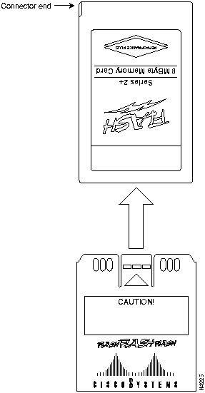
This publication describes installation and configuration procedures for the Flash memory card, which ships as a spare part and is used with the Route Switch Processor (RSP1 and RSP2), 7000 Series Route Switch Processor (RSP7000), and the Route Processor (RP). This card is an 8-, 16-, or 20-megabyte (MB), Intel Series 2+ Flash memory card, which conforms with the Personal Computer Memory Card International Association (PCMCIA) format. The RP, RSP7000, RSP1, and RSP2 Flash memory cards are identical except that the RP Flash memory card contains a metal sleeve. The RSP7000 requires Cisco IOS Release 10.3(9) or later.
The Flash memory card is used to store and boot Cisco Internetwork Operating System (Cisco IOS) software images and interface processor microcode images, and can be used as a server to store software and microcode images for other systems. The spare Flash memory card is shipped blank; you must format it before using it. Procedures for formatting the card are included in this publication.
Flash memory card product numbers are router specific, as described in Table 1.
Table 1 : Routers and Flash Memory Card Product Numbers
| Routers | Processor Card | Flash Memory Card |
|---|---|---|
| Cisco 7505 | RSP1 | MEM-RSP-FLC8M=
MEM-RSP-FLC16M= MEM-RSP-FLC20M= |
| Cisco 7507 and Cisco 7513 | RSP2 | MEM-RSP-FLC8M=
MEM-RSP-FLC16M= MEM-RSP-FLC20M= |
| Cisco 7010 | RP, RP64MB
RSP7000 |
MEM-RP-FLC8M=1
MEM-RP-FLC16M=1 MEM-RSP-FLC8M= MEM-RSP-FLC16M= MEM-RSP-FLC20M= |
| Cisco 7000 | RP, RP64MB
RSP7000 |
MEM-RP-FLC8M=1
MEM-RP-FLC16M=1 MEM-RSP-FLC8M= MEM-RSP-FLC16M= MEM-RSP-FLC20M= |
The Flash memory card is sensitive to electrostatic discharge (ESD) damage. Observe appropriate ESD-preventive procedures when handling the card.
In this publication, the first sections follow a chronological order typical of many Flash memory card installations: insert the card, format the card, copy an image to the card, and make that image bootable. The rest of the sections contain information about typical operations:
Preventing Electrostatic Discharge Damage
Electrostatic discharge (ESD) damage, which can occur when electronic cards or components are improperly handled, results in complete or intermittent failures. A processor module comprises a printed circuit board that is fixed in a metal carrier. Electromagnetic interference (EMI) shielding, connectors, and a handle are integral components of the carrier. Although the metal carrier helps to protect the board from ESD, use a preventive antistatic strap whenever handling a processor module.
Following are guidelines for preventing ESD damage:
![]()
Locating the RSP1, RSP2, RP, or RSP7000
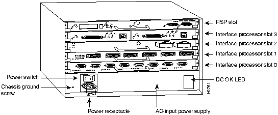
In the Cisco 7505, access to the RSP1, which contains the PCMCIA slots for the Flash memory card, is from the rear. The top processor slot, called the RSP slot, is reserved for the RSP1. (See Figure 1.)
Figure 1 : Cisco 7505 (Interface Processor End)
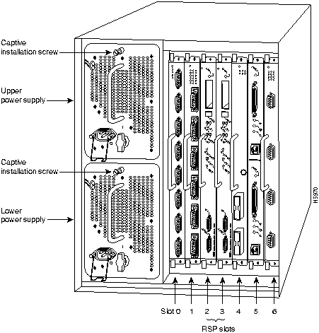
In the Cisco 7507, access to the RSP2, which contains the PCMCIA slots for the Flash memory card, is from the rear. Chassis slots 2 and 3, labeled RSP slots, are reserved for the RSP2. (See Figure 2.)
Figure 2 : Cisco 7507, Interface Processor End
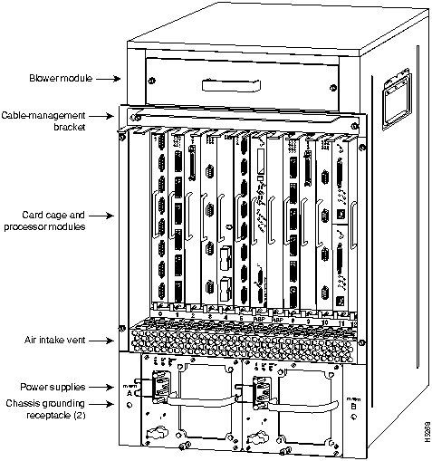
In the Cisco 7513, access to the RSP2, which contains the PCMCIA slots for the Flash memory card, is from the rear. (See Figure 3.) slot 6 or 7, labeled RSP, are reserved for the RSP2.
Figure 3 : Cisco 7513 (Interface Processor End)
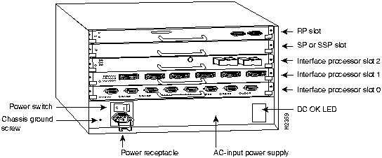
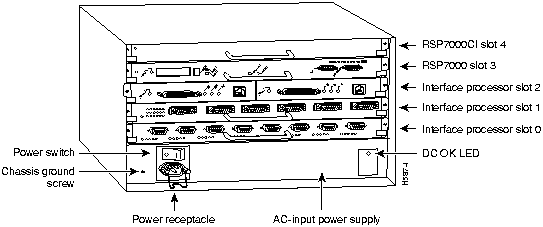
In the Cisco 7010, access to the RP, which contains the PCMCIA slot for the Flash memory card, is from the rear. The top processor slot is reserved for the RP. (See Figure 4.)
Figure 4 : Cisco 7010 (Interface Processor End)
In the Cisco 7010 equipped with the RSP7000, the PCMCIA slots for the Flash memory card are located in the RSP7000, which is installed in slot 3 (labeled 7000 RSP). (See Figure 5.)
Figure 5 : Cisco 7010 with RSP7000 and RSP7000CI Installed
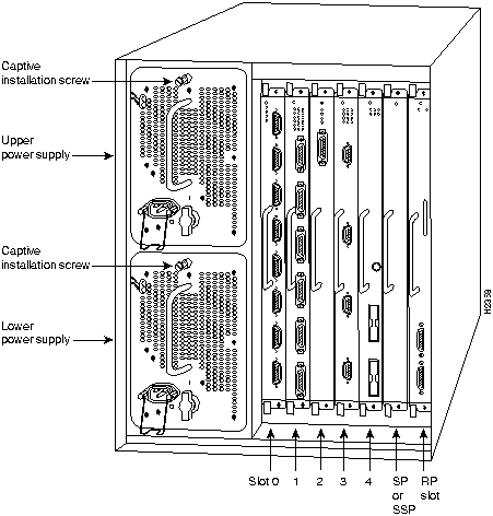
In the Cisco 7000, access to the RP, which contains the PCMCIA slot for the Flash memory card, is from the rear. (See Figure 6.) Slot 6, labeled RP, is reserved for the RP card.
Figure 6 : Cisco 7000 (Interface Processor End)
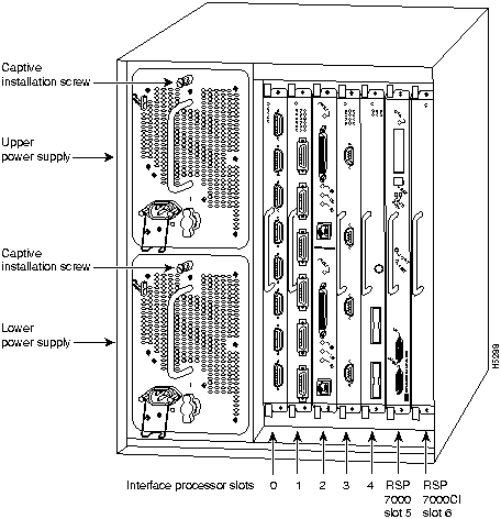
In the Cisco 7000 equipped with the RSP7000, the PCMCIA slots for the Flash memory card are located in the RSP7000, which is installed in slot 5 (labeled 7000 RSP). (See Figure 7.)
Figure 7 : Cisco 7000 with RSP7000 and RSP7000CI Installed
Installing and Removing the Flash Memory Card in an RSP or RSP7000
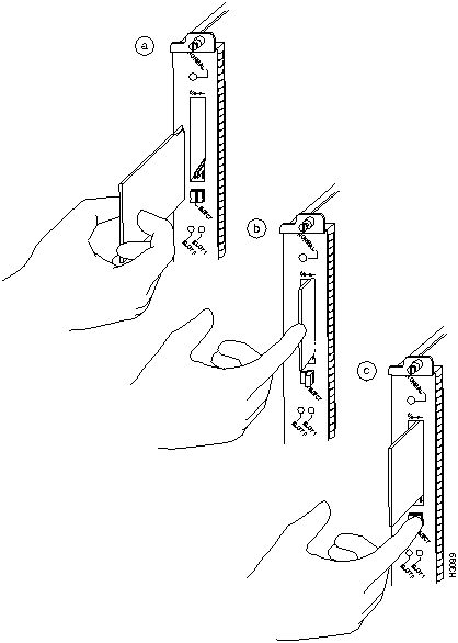
The RSP and RSP 7000 have two PCMCIA slots---slot 0 and slot 1---into which you can install a Flash memory card. In the RSP1, slot 0 is on the bottom and slot 1 on the top (see Figure 8). In the RSP2, slot 0 is on the left and slot 1 is on the right (see Figure 9). Both slots can be used at the same time. The following procedure is a generic one and can be used for a Flash memory card in either slot position.
Following is the procedure for installing and removing a Flash memory card:
Figure 8 : Installing and Removing a Flash Memory Card (RSP1 and RSP7000)
Figure 9 : Installing and Removing a Flash Memory Card (RSP2 and RSP7000)
Installing and Removing the Flash Memory Card in an RP
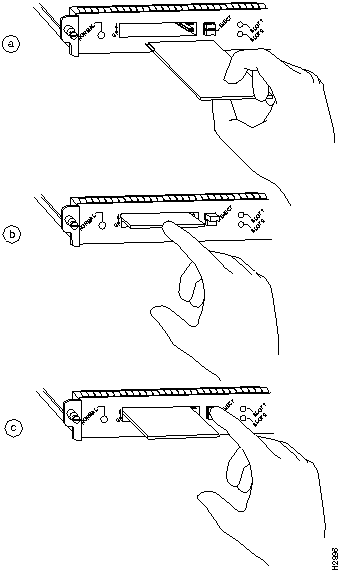
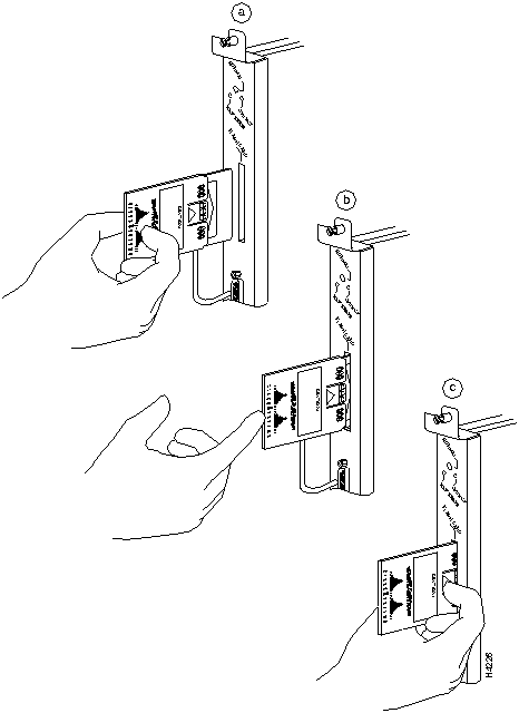
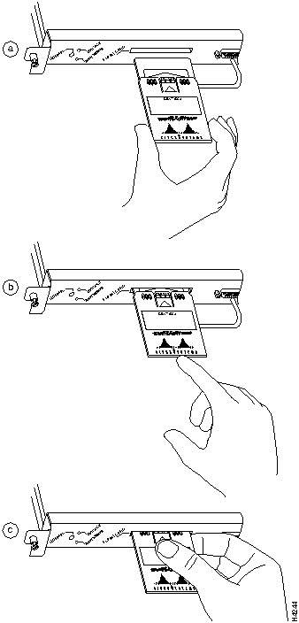
The RP has one PCMCIA slot into which you can install a Flash memory card. (See Figure 11 or Figure 12.)
Following is the procedure for installing and removing a Flash memory card:
Figure 10 : Installing the Metal Sleeve
Figure 11 : Installing and Removing a Flash Memory Card (RP in a Cisco 7000)
Figure 12 : Installing and Removing a Flash Memory Card (RP in a Cisco 7010)
Formatting a Flash Memory Card in the RSP or RSP7000
Before you can use a new Flash memory card, you must format it.
If you plan to use a Flash memory card that was formatted on another type of system, see the section "Flash Memory Card Compatibility," on page 27, to determine if you need to reformat it first.
Use the following procedure to format a new Flash memory card:
The new Flash memory card is now formatted and ready to use.
Formatting a Flash Memory Card in the RP
Before you can use a new Flash memory card, you must format it. Also, if you plan to boot from a Flash memory card that was formatted on an RSP-based system (Cisco 7500 series or a Cisco 7000 series router with an RSP7000), you must first reformat the card on your system.
Use the following procedure to format a new Flash memory card (the procedure assumes you have already booted your router):
The new Flash memory card is now formatted and ready to use.
Copying an Image into a Flash Memory Card
With the Flash memory card formatted, you can now copy an image into it. The following procedure assume the following:
Following is the procedure for copying a file (called new.image) into the Flash memory card:
Making the Flash Memory Card Image Bootable
Use the following series of commands to make the image (the file named new.image) bootable. Note that, since the configuration register must be set to 0x2102, the config-register command is part of the sequence.
When the system reloads it will boot the image new.image from the Flash memory card in slot 0.
Copying Bootable Images between Flash Memory Cards (RSP and RSP7000 only)
As future releases of Cisco IOS images become available, you will receive these images either as a file booted from a network server, a file on floppy disk, or a file on a Flash memory card.
The following scenario describes how to use a newly released image on a Flash memory card in a system that has an older image on a Flash memory card in slot 0 and a default boot image in the onboard Flash SIMM.
For this scenario, the filenames are as follows:
You will copy the new image from the new Flash memory card onto the Flash memory card that contains the old image.
When the system reloads, it will boot the file image.new from the Flash memory card in slot 0.
Enabling Booting from Flash Memory on an RSP or RSP7000
To enable booting from Flash memory, set configuration register bits 3, 2, 1, and 0 to a value between 2 and 15 in conjunction with the boot system flash [filename] configuration command.
Following are definitions of the various Flash memory-related boot commands:
boot system flash---Boots the first file in onboard Flash memory
boot system flash flash:---Boots the first file in onboard Flash memory
boot system flash herfile---Boots the file named "herfile" on onboard Flash memory
boot system flash slot0:---Boots the first file on Flash memory card in slot 0
boot system flash flash:hisfile ---Boots the file named "hisfile" on onboard Flash memory
boot system flash slot0:myfile ---Boots the file named "myfile" on the Flash memory card in slot 0
To enter configuration mode and specify a Flash memory filename in the PCMCIA slot from which to boot, enter the configure terminal command at the enable prompt, as follows:
To disable Break and enable the boot system flash slot0: command, enter the config-register command with the value shown in the following example:
To save the new configuration to memory, use the copy running-config startup-config command as follows:
When you enter boot commands, pay attention to the use of the space bar, which influences the way the router interprets the command. For example, notice the difference in the following commands:
In the first case, the router boots the file specified (myfile). In the second case, the router finds the filename field blank and boots the first file on the Flash memory card.
Enabling Booting from Flash Memory on an RP
To enable booting from Flash memory, set configuration register bits 3, 2, 1, and 0 to a value between 2 and 15 in conjunction with the boot system flash [filename] configuration command.
Following are definitions of the various Flash memory-related boot commands:
boot system flash---Boots the first file in onboard Flash memory
boot system flash flash:---Boots the first file in onboard Flash memory
boot system flash herfile---Boots the file named "herfile" on onboard Flash memory
boot system flash slot0:---Boots the first file on Flash memory card in the PCMCIA slot (slot 0)
boot system flash flash:hisfile ---Boots the file named "hisfile" on onboard Flash memory
boot system flash slot0:myfile ---Boots the file named "myfile" on the Flash memory card in the PCMCIA slot (slot 0)
To enter configuration mode and specify a Flash memory filename in the PCMCIA slot from which to boot, enter the configure terminal command at the enable prompt, as follows:
To disable Break and enable the boot system flash slot0: command, enter the config-register command with the value shown in the following example:
To save the new configuration to memory, use the copy running-config startup-config command as follows:
When you enter boot commands, pay attention to the use of the Spacebar, which influences the way the router interprets the command. For example, notice the difference in the following commands:
In the first case, the router boots the file specified (myfile). In the second case, the router finds the filename field blank and boots the first file on the Flash memory card.
Copying to Flash Memory on an RSP or RSP7000
Copying a new image to Flash memory might be required whenever a new image or maintenance release becomes available.
Use the command copy tftp:filename [ bootflash | slot0 | slot1 ]:filename for the copy procedure where tftp:filename is the source of the file and [ bootflash | slot0 | slot1 ]:filename is the destination in onboard Flash memory or on either of the Flash memory cards.
An example of the copy tftp:filename command follows:
Copying to Flash Memory on an RP
Copying a new image to Flash memory might be required whenever a new image or maintenance release becomes available.
Use the command copy tftp:filename [ bootflash | slot0]:filename for the copy procedure where tftp:filename is the source of the file and [ bootflash | slot0]:filename is the destination in onboard Flash memory or on either of the Flash memory cards.
An example of the copy tftp:filename command follows:
RSP-Specific Flash Memory Commands
Following are additional commands related to the Flash memory in the single in-line memory module (SIMM) on the RSP or RSP7000 (called bootflash) and in PCMCIA cards. (The following example assumes you are currently in PCMCIA slot 0.) You can determine which PCMCIA slot you are accessing using the pwd command as follows:
You can move between Flash memory media using the cd [ bootflash | slot0 | slot1 ] command as follows:
You can list the directory of any Flash memory media using the dir [ bootflash | slot0 | slot1 ] command as follows:
You can delete a file from any Flash memory media using the delete command as follows:
To verify that the delete command was successful, use the dir/all/long command.
The squeeze command permanently removes files, which are marked as deleted, and pushes all other undeleted files together to eliminate spaces between them.
Following is the syntax of the squeeze command:
To prevent loss of data due to sudden power loss, the "squeezed" data is temporarily saved to another location of Flash memory, which is specially used by the system.
In the preceding command display output, the character "e" means this special location has been erased (which must be performed before any write operation). The character "b" means that the data that is about to be written to this special location has been temporarily copied. The character "E" signifies that the sector which was temporarily occupied by the data has been erased. The character "S" signifies that the data was written to its permanent location in Flash memory.
The squeeze command operation keeps a log of which of these functions has been performed so upon sudden power failure, it can come back to the right place and continue with the process. The character "Z" means this log was erased after the successful squeeze command operation.
A locked block of Flash memory occurs when power is lost or a Flash memory card is unplugged during a write or erase operation. When a block of Flash memory is locked, it cannot be written to or erased, and the operation will consistently fail at a particular block location. The only way to recover from locked blocks is by reformatting the Flash memory card with the format command.
Flash Memory Card Compatibility
In order to use the Flash memory card, the card must have been formatted on the same type of system. Table 2 shows which systems support using a Flash memory card without reformatting and which systems require that you reformat the card before it can be used.
Table 2 : Flash Memory Card Compatibility
Any Intel Series 2+ Flash memory card can be used on an RSP- or RP-based router. However, an RP-based router requires installation of the card's metal sleeve and must contain Cisco IOS Release 11.0 boot ROMs (SWR-G7-11.0.0=) or later. (The RP board requires Cisco IOS 11.0 in order to boot from the Flash memory card.) In addition, an RP-based router can only read up to 16 MB.
The Cisco Internetwork Operating System (Cisco IOS) software running the router contains extensive features and functionality. The effective use of many of many of these features is easier if you have more information at hand.
To obtain general information about documentation, call Customer Service at 800 553-6387 or 408 526-7208. Customer Service hours are 5:00 a.m. to 6:00 p.m. Pacific time, Monday through Friday (excluding company holidays). You can also send e-mail to For additional information on configuring the Cisco 7500 series routers and VIP2, the following documentation resources are available to you:
Cisco Connection Online (CCO), formerly Cisco Information Online (CIO), is Cisco Systems' primary, real-time support channel. Maintenance customers and partners can self-register on CCO to obtain additional content and services.
Available 24 hours a day, 7 days a week, CCO provides a wealth of standard and value-added services to Cisco's customers and business partners. CCO services include product information, software updates, release notes, technical tips, the Bug Navigator, configuration notes, brochures, descriptions of service offerings, and download access to public and authorized files.
CCO serves a wide variety of users through two interfaces that are updated and enhanced simultaneously---a character-based version and a multimedia version that resides on the World Wide Web (WWW). The character-based CCO supports Zmodem, Kermit, Xmodem, FTP, Internet e-mail, and fax download options, and is excellent for quick access to information over lower bandwidths. The WWW version of CCO provides richly formatted documents with photographs, figures, graphics, and video, as well as hyperlinks to related information.
You can access CCO in the following ways:
For a copy of CCO's Frequently Asked Questions (FAQ), contact
Copyright 1988-1996 © Cisco Systems Inc.
![]()
A Flash memory card that is shipped as part of a Cisco 75XX (or a Cisco 7000 or Cisco 7010 with an RSP7000) system contains an image. A spare Flash memory card must be formatted before use.
Router#
format slot0:
All sectors will be erased, proceed? [confirm]
Enter volume id (up to 30 characters):
MyNewCard
Formatting sector 1
Format device slot0 completed
Router#
![]()
Router#
format slot0:
All sectors will be erased, proceed? [confirm]
Enter volume id (up to 30 characters):
MyNewCard
Formatting sector 1
Format device slot0 completed
Router#
Router>
en
Password:
Router#
copy tftp:new.image slot0:new.image
20575008 bytes available on device slot0, proceed? [confirm]
Address or name of remote host [1.1.1.1]?
Loading new.image from 1.1.1.1 (via Ethernet1/0): !!!!!!!!!!!!!!!!!!!!!!!!!!!!!!
!!!!!!!!!!!!!!!!!!!!!!!!!!!!!!!!!!!!!!!!!!!!!!!!!!!!!!!!!!!!!!!!!!!!!!!!!!!!!!!!
!!!!!!!!!!!!!!!!!!!!!!!!!!!!!!!!!!!!!!!!!!!!!!!!!!!!!!!!!!!!!!!!!!!!!!!!!!!!!!!!
!!!!!!!!!!!!!!!!!!!!!!!!!!!!!!!!!!!!!!!!!!!!!!!!!!!!!!!!!!!!!!!!!!!!!!!!!!!!!!!!
!!!!!!!!!!!!!!!!!!!!!!!!!!!!!!!!!!!!!!!!!!!!!!!!!!!!!!!!!!!!!!!!!!!!!!!!!!!!!!!!
!!!!!!!!!!!!!!!!!!!!!!!!!!!!!!!!!!!!!!!!!!!!!!!!!!!!!!!!!!!!!!!!!!!!!!!!!!!!!!!!
!!!!!!!!!!!!!!!!!!!!!!!!!!!!!!!!!!!!!!!!!!!!!!!!!!!!!!!!!!!!!!!!!!!!!!!!!!!!!!!!
!!!!!!!!!!!!!!!!!!!!!!!!!!!!!!!!!!!!!!!!!!!!!!!!!!!!!!!!!!!!!!!!!!!!!!!!!!!!!!!!
!!!!!!!!!!!!!!!!!!!!!!!!!!!!!!!!!!!!!!!!!!!!!!!!!!!!!!!!!!!!!!!!!!!!!!!!!!!!!!!!
!!!!!!!!!!!!!!!!!!!!!!!!!!!!!!!!!!!!!!!!!!!!!!!!!!!!!!!!!!!!!!!!!!!!!!!!!!!!!!!!
!!!!!!!!!!!!!!!!!!!!!!!!!!!!!!!!!!!!!!!!!!!!!!!!!!!!!!!!!!!!!!!!!!!!!!!!!!!!!!!!
!!!!!!!!!!!!!!!!!!!!!!!!!!!!!!!!!!!!!!!!!!!!!!!!!!!!!!!!!!!!!!!!!!!!!!!!!!!!!!!!
!!!!!!!!!!!!!!!!!!!!!!!!!!!!!!!!!!!!!!!!!!!!!!!!!!!!!!!!!!!!!!!!!!!!!!!!!!!!!!!!
!!!!!!!!!!!!!!!!!!!!!!!!!!!!!!!!!!!!!!!!!!!!!!!!!!!!!!!!!!!!!!!!!!!!!!!!!!!!!!!!
!!!!!!!!!!!!!!!!!!!!!!!!!!!!!!!!!!!!!!!!!!!!!!!!!!!!!!!!!!!!!!!!!!!!!!!!!!!!!!!!
!!!!!!!!!!!!!!!!!!!!!!!!!!!!!!!!!!!!!!!!!!!!!!!!!!!!!!!!!!!!!!!!!!!!!!!!!!!!!!!!
!!!!!!!!!!!!!!!!!!!!!!!!!!!!!!!!!!!!!!!!!!!!!!!!!!!!!!!!!!!!!!!!!!!!!!!!!!!!!!!!
!!!!!!!!!!!!!!!!!!!!!!!!!!!!!!!!!!!!!!!!!!!!!!!!!!!!!!!!!!!!!!!!!!!!!!!!!!!!!!!!
!!!!!!!!!!!!!!!!!!!!!!!!!!!!!!!!!!!!!!!!!!!!!!!!!!!!!!!!!!!
[OK - 7799951/15599616 bytes]
CCCCCCCCCCCCCCCCCCCCCCCCCCCCCCCCCCCCCCCCCCCCCCCCCCCCCCCCCCCCCCCCCCCCCCCCCCCCCCCC
CCCCCCCCCCCCCCCCCCCCCCCCCCCCCCCCCCCCCCCCCCCCCCCCCCCCCCCCCCCCCCCCCCCCCCCCCCCCCCCC
CCCCCCCCCCCCCCCCCCCCCCCCCCCCCCCCCCCCCCCCCCCCCCCCCCCCCCCCCCCCCCCCCCCCCCCCCC
Router#
Router#
config terminal
Router(config)#
no boot system
Router(config)#
boot system flash slot0:new.image
Router(config)#
config-register 0x2102
Crtl-z
Router#
copy running-config startup-config
Router#
reload
Router>
en
Password:
Router#
Router#
copy slot1:image.new slot0:image.new
Router#
config t
Router(config)#
no boot system
Router(config)#
boot system flash slot0:image.new
Crtl-z
Router#
copy running-config startup-config
Router#
reload
Router# configure terminal
Enter configuration commands, one per line. End with CTRL-Z.
Router(config)# boot system flash slot0:myfile
Router(config)# config-reg 0x2102

To exit configuration mode, enter Cntl-Z as follows:
Crtl-z
Router#
Router# copy running-config startup-config
Router(config)# boot system flash slot0:myfile (correct command)
Router(config)# boot system flash slot0: myfile (incorrect command)
Router# copy tftp:myfile1 slot0:myfile1
20575008 bytes available on device slot0, proceed? [confirm]
Address or name of remote host [1.1.1.1]?
Loading new.image from 1.1.1.1 (via Ethernet1/0): !!!!!!!!!!!!!!!!!!!!!!!!!!!!!!
!!!!!!!!!!!!!!!!!!!!!!!!!!!!!!!!!!!!!!!!!!!!!!!!!!!!!!!!!!!!!!!!!!!!!!!!!!!!!!!!
!!!!!!!!!!!!!!!!!!!!!!!!!!!!!!!!!!!!!!!!!!!!!!!!!!!!!!!!!!!!!!!!!!!!!!!!!!!!!!!!
!!!!!!!!!!!!!!!!!!!!!!!!!!!!!!!!!!!!!!!!!!!!!!!!!!!!!!!!!!!!!!!!!!!!!!!!!!!!!!!!
!!!!!!!!!!!!!!!!!!!!!!!!!!!!!!!!!!!!!!!!!!!!!!!!!!!!!!!!!!!!!!!!!!!!!!!!!!!!!!!!
!!!!!!!!!!!!!!!!!!!!!!!!!!!!!!!!!!!!!!!!!!!!!!![OK - 7799951/15599616 bytes]
CCCCCCCCCCCCCCCCCCCCCCCCCCCCCCCCCCCCCCCCCCCCCCCCCCCCCCCCCCCCCCCCCCCCCCCCCCCCCCCC
CCCCCCCCCCCCCCCCCCCCCCCCCCCCCCCCCCCCCCCCCCCCCCCCCCCCCCCCCCCCCCCCCCCCCCCCCCCCCCCC
CCCCCCCCCCCCCCCCCCCCCCCCCCCCCCCCCCCCCCCCCCCCCCCCCCCCCCCCCCCCCCCCCCCCCCCCCC
Router#
Router# pwd
slot0
Router# cd slot0
slot0
Router# cd slot1
Router# pwd
slot1
Router# dir
-#- -length- -----date/time------ name
1   4601977  May 19 1994 09:42:19 myfile1
6   679      May 19 1994 05:43:56 todays--config
7   1        May 19 1994 09:54:53 fun1
Router# delete slot0:fun1
Router# dir
-#- -length- -----date/time------ name
1   4601977  May 19 1994 09:42:19 myfile1
6   679      May 19 1994 05:43:56 todays--config
Router# squeeze slot0:
All deleted files will be removed, proceed? [confirm]
Squeeze operation may take a while, proceed? [confirm]
ebESZ
![]()
Formatted In
Installed In
Usable Without Reformatting
Must Be Reformatted
RSP1
RSP1
X
RSP1
RSP2
X1
RSP7000
RSP1 or RSP2
X
RSP7000
RP
X
RSP1
RP
X
RSP2
RSP1
X1
RSP2
RSP2
X
RSP2
RP
X
RP
RP
X
RP
RSP1
X
RP
RSP2
X
RP
RSP7000
X
1 Cisco IOS Release 10.3(572) and higher (for example Cisco IOS 10.3[6]) make RSP1and RSP2 formats compatible. In Cisco IOS Release 10.3(5) and lower, RSP1 and RSP2 formats are not compatible and require you to reformat the card before it can be used.
cs-rep@cisco.com
. You can also refer to the Cisco Information Packet that shipped with your router.
http://www.cisco.com.
cco.cisco.com.
ccohelp@cisco.com.
For additional information, contact
ccoteam@cisco.com.
tac@cisco.com.
To obtain general information about Cisco Systems, Cisco products, or upgrades, contact 800 553-6387, 408 526-7208, or
csrep@cisco.com.

![]()
![]()
![]()
![]()
![]()
![]()
![]()
![]()