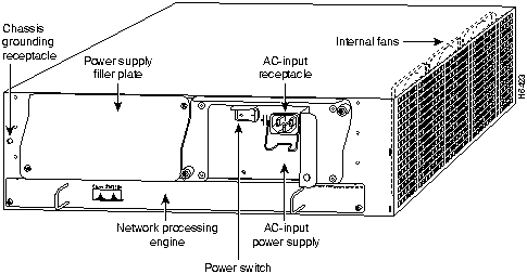
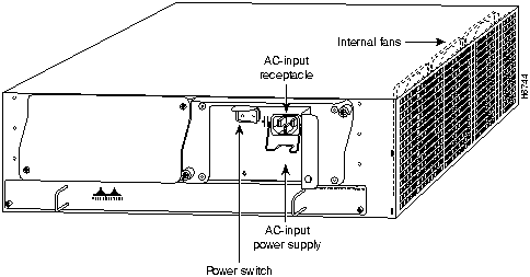
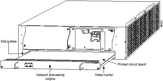
The rear of the Cisco 7200 series routers provides access to the network processing engine and up to two 280W, AC-input or DC-input power supplies (refer to Figure 4).
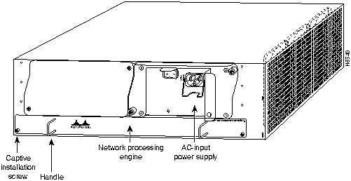
The network processing engine has no external connectors or LEDs. There are two handles for removing and installing the network processing engine and two captive installation screws for securing it to the chassis.
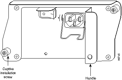
A fully configured Cisco 7200 series router operates with only one installed power supply; however, a second, optional power supply provides hot-swappable, load-sharing, redundant power. The power supply has the router's main power switch and either an AC-input power receptacle, or a hardwired DC-input power cable (depending on the type of installed power supply). Adjacent to the power supply bays there is a 10 x 32-inch chassis ground receptacle that provides a chassis ground connection for ESD equipment or a grounding wire (refer to Figure 4).
Note The Cisco 7200 routers come equipped with either one 280W AC-input or one 280W DC-input power supply; a second 280W AC-input or DC-input power supply is available for the router. Figure 4 shows the rear of a Cisco 7200 series router that is configured with a single 280W AC-input power supply. (A power supply filler plate is installed over the second power supply bay.)
Three internal fans draw cooling air into the chassis interior and across internal components to maintain an acceptable operating temperature (refer to Figure 4). The three fans are enclosed in a tray that is located in the subchassis.
The I/O controller, port adapters, power supplies, and network processing engine slide into their respective chassis slots and connect directly to the router's midplane; there are no internal cables to connect. The midplane distributes DC power from the power supplies to the I/O controller, port adapters, fan tray, and network processing engine.
Memory Systems Overview
The Cisco 7200 series memory systems are divided between the I/O controller and the network processing engine. The memory systems provide the following functions:
- Main memory (DRAM)---Stores the running configuration and routing tables. The Cisco Internetwork Operating System (Cisco IOS) software executes from main memory.
- Shared memory---Used for packet buffering by the router's network interfaces.
- Flash memory SIMM---Stores the boot helper software. The boot helper image allows you to boot the router when Flash memory does not contain a valid system image.
- Flash memory card(s)---Stores the default Cisco IOS software image.
- Erasable programmable read-only memory (EPROM)-based memory---The ROM monitor permits you to boot the Cisco IOS image from Flash memory if a boot helper image is not present in boot Flash memory.
- Nonvolatile random-access memory (NVRAM)---Stores the system configuration, environmental monitoring logs, and the virtual configuration register.
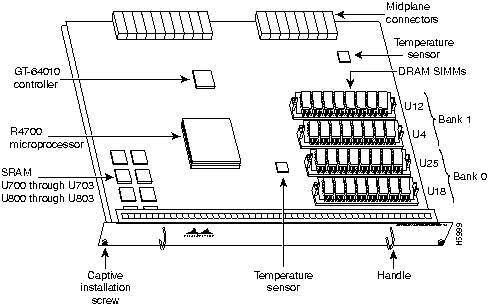
Table 1 lists the Cisco 7200 series processor and memory specifications. Table 2 lists the network processing engine factory-installed DRAM configurations and their product numbers. Figure 5 shows the I/O controller with the optional Fast Ethernet port. Figure 6 shows the network processing engine.
Table 1 : Cisco 7206 Processor and Memory Specifications
| Network processing engine
|
Processor
|
150-MHz Orion RISC1
|
Socket U201
|
|
|
Main memory (DRAM)2
|
16 to 128 MB
|
Bank 1: U12 and U4
Bank 0: U25 and U18
|
|
|
SRAM3
|
1 MB
|
Sockets U700 through U703
Sockets U800 through U803
|
|
|
Unified secondary cache
|
512 KB
|
U2, U10, U14, and U26
|
I/O Controller
|
Flash SIMM
|
4 MB
|
Socket U99
|
|
|
Flash memory card
|
8 to 20 MB
|
PCMCIA
Slot 0 and Slot 1
|
|
|
Nonvolatile RAM
|
128 KB
|
Socket U41
|
|
|
Boot ROM4
|
256 KB
|
Socket U20
|
1 RISCreduced instruction set computing
2 DRAMdynamic random-access memory
3 SRAMstatic random-access memory
4 ROMread-only memory
Table 2 : DRAM SIMM Configurations
| 16 MB
|
U18 and U25
|
2 8-MB SIMMs
|
U4 and U12
|
--
|
MEM-NPE-16MB1
|
|
|
|
|
|
|
|
| 24 MB
|
U18 and U25
|
2 8-MB SIMMs
|
U4 and U12
|
2 4-MB SIMMs
|
MEM-NPE-24MB
|
| 32 MB
|
U18 and U25
|
2 16-MB SIMMs
|
U4 and U12
|
--
|
MEM-NPE-32MB1
|
|
|
|
|
|
|
|
| 64 MB
|
U18 and U25
|
2 32-MB SIMMS
|
U4 and U12
|
--
|
MEM-NPE-64MB1
|
|
|
|
|
|
|
|
| 128 MB
|
U18 and U25
|
2 32-MB SIMMs
|
U4 and U12
|
2 32-MB SIMMs
|
MEM-NPE-128MB1
|
1 These products are also available as DRAM upgrades. For example, to upgrade a network processing engine from 16 MB to 32 MB of DRAM, order product number MEM-NPE-16MB=.
Figure 5 : Input/Output Controller---With Optional Fast Ethernet Port
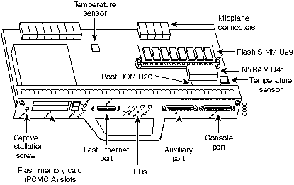
Figure 6 : Network Processing Engine
Proceed to the following section "Installation Prerequisites."
Installation Prerequisites
This section provides a list of parts and tools you need to remove main, Flash, and ROM monitor memory in the Cisco 7200 series routers. This section also includes safety and ESD-prevention guidelines to help you avoid injury to yourself and damage to the equipment.
List of Parts and Tools
You need the following tools and parts to replace the main, Flash, and ROM monitor memory from the network processing engine and the I/O controller. If you need additional equipment, contact a service representative for ordering information.
- New DRAM or Flash single in-line memory modules (SIMMs), or ROM monitor device
- Number 2 Phillips screwdriver
- 3/16-inch flat-blade screwdriver
- Your own ESD-prevention equipment or the disposable grounding wrist strap included with all upgrade kits, FRUs, and spares
- An antistatic mat or surface
- Small needlenose pliers
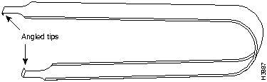
In addition, the ROM monitor device replacement requires a DIP-type integrated circuit (IC) removal tool (see Figure 7) or a small flat-blade screwdriver.
Figure 7 : IC Removal Tool
Safety Guidelines
Following are safety guidelines that you should follow when working with any equipment that connects to electrical power or telephone wiring.
Electrical Equipment Guidelines
Follow these basic guidelines when working with any electrical equipment:
- Before beginning any procedures requiring access to the chassis interior, locate the emergency power-off switch for the room in which you are working.
- Disconnect all power and external cables before moving a chassis.
- Do not work alone when potentially hazardous conditions exist.
- Never assume that power has been disconnected from a circuit; always check.
- Do not perform any action that creates a potential hazard to people or makes the equipment unsafe.
- Carefully examine your work area for possible hazards such as moist floors, ungrounded power extension cables, and missing safety grounds.
Telephone Wiring Guidelines
Use the following guidelines when working with any equipment that is connected to telephone wiring or to other network cabling:
- Never install telephone wiring during a lightning storm.
- Never install telephone jacks in wet locations unless the jack is specifically designed for wet locations.
- Never touch uninsulated telephone wires or terminals unless the telephone line has been disconnected at the network interface.
- Use caution when installing or modifying telephone lines.
Preventing Electrostatic Discharge Damage
Electrostatic discharge (ESD) damages equipment and impairs electrical circuitry. ESD occurs when printed circuit boards or memory SIMMs are improperly handled and results in complete or intermittent failures.
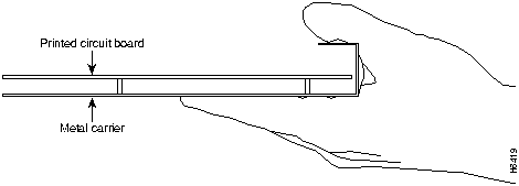
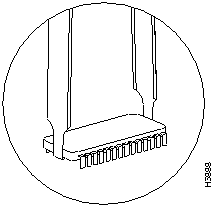
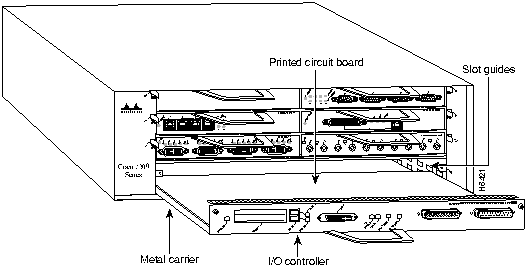
The I/O controller and network processing engine consist of a printed circuit board that is fixed in a metal carrier. Electromagnetic interference (EMI) shielding, connectors, and a handle are integral components of the carrier. Handle the I/O controller and network processing engine by their carrier edges and handle; never touch the printed circuit board or connector pins.
Figure 8 shows the location of a printed circuit board when it is installed in a network processing engine or I/O controller metal carrier. Do not touch the printed circuit board when handling either component.
Figure 8 : Handling the I/O Controller and the Network Processing Engine
Handle SIMMs by the edges only; avoid touching the memory modules, pins, or traces (the metal fingers along the connector edge of the SIMM) (refer to Figure 9). Always wear a preventive antistatic strap whenever handling SIMMs.
Figure 9 : Handling a SIMM

Although the metal carrier helps to protect the I/O controller and the network processing engine from ESD, wear a preventive antistatic strap whenever handling the I/O controller or network processing engine. Ensure that the strap makes good skin contact and connect the strap's clip to an unpainted chassis surface to safely channel unwanted ESD voltages to ground.
If no wrist strap is available, ground yourself by touching the metal part of the chassis.
 Caution Use a number 2 Phillips's screwdriver to tighten the captive installation screws on the I/O controller and the network processing engine. These screws prevent accidental removal, provide proper grounding for the router, and help to ensure that the I/O controller and network processing engine are properly seated in the router midplane.
Following are guidelines for preventing ESD damage:
- Always use an ESD wrist strap or ankle strap when installing or replacing the I/O controller, network processing engine, or port adapters. Ensure that the ESD strap makes contact with your skin.
- Handle the I/O controller, network processing engine, or port adapters by their metal carrier edges and handle; avoid touching the printed circuit board or any connector pins.
- When removing the I/O controller, network processing engine, or port adapters, place them on an antistatic surface with the printed circuit board components facing upward, or in a static shielding bag. If you are returning an I/O controller, network processing engine, or port adapter to the factory, immediately place it in a static shielding bag.

Caution Periodically check the resistance value of the antistatic strap. The measurement should be within the range of 1 and 10 megohms.
Ensuring Easy Access to the Router
If your Cisco 7200 series router is installed in a standard 19-inch rack or in a 19-inch Telco rack, cables from other equipment in the rack may obstruct access to the rear of the router. Also, rack power strips or other permanent fixtures may obstruct access to the router. Review the following guidelines to ensure easy access to the rear of the router when it is installed in a rack. If the router is not installed in a rack, or if you already have clear access to the rear of the router, proceed to the following section "Removing and Replacing Memory SIMMs and the Boot ROM."
Use the following guidelines to ensure easy access to the rear of the router when it is installed in a rack:
- Ensure that you have at least three to four feet of working space at the rear of the router.
- If cables from other equipment in the rack fall in front of the rear end of the router, carefully gather the cables (using care not to strain them) and use cable ties to anchor them away from the rear of the router.
- If access to the rear of the router is partially blocked by a power strip or some other permanent rack fixture, detach the router from the rack and carefully slide it forward until there is enough clearance to remove the power supply, the network processing engine, and the subchassis from the router. Detailed steps for detaching the router from the rack are contained in the following section "Removing the Network Processing Engine."

Caution Make sure that at least one other person is available to support the front of the router as you slide it out from the rack and, if necessary, to continue to support it while you remove and insert the power supply, network processing engine, or subchassis.
Removing and Replacing Memory SIMMs and the Boot ROM
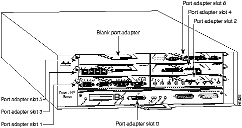
There is one Flash memory SIMM on the I/O controller (refer to Figure 5) and four main memory (DRAM) SIMMs on the network processing engine (refer to Figure 6); the replacement instructions are the same for the Flash memory and DRAM SIMMs.
The following sections explain how to remove and replace the Flash memory SIMM on the I/O controller, and how to remove and replace the DRAM SIMMs from the network processing engine. Removing and replacing the SIMMs involves the following steps:
- Powering Down the Router and Disconnecting Input Power
- Removing the Input/Output Controller
- Removing the Network Processing Engine
- Removing Memory SIMMs
- Installing New Memory SIMMs
- Removing the Boot ROM
- Replacing the Input/Output Controller
- Replacing the Network Processing Engine
- Reconnecting Input Power and Powering Up the Router
These tasks are described in detail in the following subsections.
Note The tasks for removing and replacing the I/O controller and network processing engine in the Cisco 7204 and the Cisco 7206 are the same. Therefore, the illustrations in the following sections show the Cisco 7206, unless indicated otherwise.
Powering Down the Router and Disconnecting Input Power
To power down a Cisco 7200 series router that has an installed AC-input power supply, complete the following steps:
Note Before powering down the router, use the copy running-config startup-config command to save the router's running configuration to nonvolatile memory.
Step 1 Facing the rear of the router, place the power switch (on the power supply) in the OFF (0) position. Repeat this action if a second power supply is installed in the router.
Step 2 Observe the following items:
- The green OK LED on the power supply turns off
- The fans stop operating
- The LEDs on the I/O controller turn off
- The LEDs on the port adapters turn off
To disconnect AC-input power to a Cisco 7200 series router, complete the following steps:
Step 1 Unplug input power cable from the power source.
Step 2 Push down on the cable-retention clip that secures the input power cable to the router's power supply.
Step 3 Unplug the other end of the input power cable from the power supply (refer to Figure 10).
Figure 10 : Disconnecting Power from a Cisco 7200 Series AC-Input Power Supply
Step 4 Repeat Step 2 through Step 1 if a second power supply is installed.
This completes the procedure for powering down the router and disconnecting input power. Proceed to the following section "Removing the Input/Output Controller."
Removing the Input/Output Controller
To remove an I/O controller from a Cisco 7200 series router, complete the following steps:
Step 1 Power down the router and disconnect the input power cable. Refer to the section "Powering Down the Router and Disconnecting Input Power" earlier in this document.
Step 2 Attach an ESD-preventative wrist strap between you and an unfinished chassis surface.
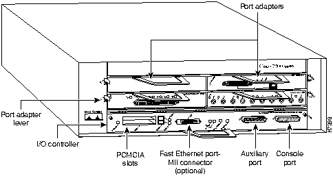
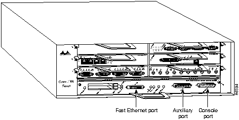
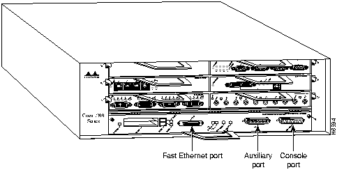
Step 3 Disconnect the cables from the I/O controller's console, auxiliary, and Fast Ethernet (if present) ports (refer to Figure 11).
Figure 11 : Cisco 7200 Series Input/Output Controller Ports, Handle, and Captive Screws
Step 4 Remove the Flash memory cards (if present) from the I/O controller's PCMCIA slots. Refer to the section "Installing and Removing a Flash Memory Card" later in this document.
Step 5 Using a number 2 Phillips screwdriver, loosen the two captive installation screws on the faceplate of the I/O controller (refer to Figure 11).
Step 6 Grasp the I/O controller handle and carefully pull the controller from its chassis slot.
 Caution Handle the I/O controller by the carrier edges and handle only; never touch the printed circuit board components or connector pins (refer to Figure 8).
Step 7 Place the I/O controller on an antistatic surface with its components facing upward, or in a static shielding bag. If you are returning the I/O controller to the factory, immediately place it in a static shielding bag.
This completes the procedure for removing the I/O controller. Proceed to the section "Removing the Network Processing Engine."
Removing the Network Processing Engine
To remove the network processing engine from a Cisco 7200 series router, complete the following steps:
Note The weight of installed power supplies in your Cisco 7200 series router might make it difficult to remove the network processing engine. If you have difficulty, consider removing power supplies from the chassis and then removing the network processing engine. Refer to the section "Removing and Installing an AC-Input Power Supply" on page 28 of this document for information on removing and replacing an installed power supply.
Step 1 Power down the router and disconnect its input power cable. Refer to the section "Powering Down the Router and Disconnecting Input Power" earlier in this document.
Step 2 Attach an ESD-preventative wrist strap between you and an unfinished chassis surface.
Step 3 Using a number 2 Phillips screwdriver, loosen the two captive installation screws on the faceplate of the network processing engine (refer to Figure 12).
- If the router is not installed in a standard 19-inch rack or in a Telco rack, skip to Step 7. If the router is installed in a rack, determine if any permanent rack fixtures, such as a power strip, are obstructing access to the power supply. If a rack fixture is obstructing access to the power supply, proceed with Step 4.
Step 4 Using a 3/16-inch flat-blade screwdriver, loosen the four screws that secure the router to the front mounting strips of the rack.
Step 5 Position at least one person in front of the rack to support the front underside of the router.
Step 6 From the rear of the rack, carefully push the front of the router out of the rack until there is enough clearance to remove the network processing engine.
Step 7 Grasp the two network processing engine handles and carefully pull the network processing engine from its chassis slot.
 Caution Handle the network processing engine by the carrier edges and handles only; never touch the printed circuit board components or connector pins (refer to Figure 8).
Figure 12 : Cisco 7200 Series Network Processing Engine Captive Screws and Handles
Step 8 Place the network processing engine on an antistatic surface with its printed circuit board components facing upward, or in a static shielding bag.
This completes the procedure for removing the network processing engine. Proceed to the section "Removing Memory SIMMs."
Removing Memory SIMMs
This section explains how to remove memory SIMMs that are installed on the I/O controller and the network processing engine. To remove the installed SIMMs, complete the following steps:
Step 1 Attach an ESD-preventive wrist strap between you and an unpainted router surface.
Step 2 Place the I/O controller or the network processing engine on an antistatic mat or surface (ensure that you are wearing an antistatic device, such as a wrist strap).
Step 3 Position the I/O controller or the network processing engine so that the handle is away from you and the edge connector is toward you.
Step 4 Locate the SIMMs.
- The Flash SIMM on the I/O controller occupies socket U99 (refer to Figure 5).
- The DRAM SIMMs on the network processor engine occupy sockets U18, U25, U4, and U12 (refer to Figure 6).
Note SIMMs installed in your system might look different from the SIMMs shown in the following illustrations.
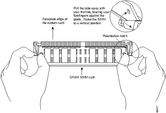
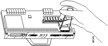
Step 5 Release the spring clips from the SIMM that you want to remove, and release the SIMM from the socket (refer to Figure 13).
Figure 13 : Releasing the SIMM Spring Clips
Step 6 When both ends of the SIMM are released from the socket, grasp the ends of the SIMM with your thumb and forefinger and pull the SIMM completely out of the socket. Handle the edges of the SIMM only; avoid touching the memory module or pins, and the metal traces, or fingers, along the socket edge.
Step 7 Place the SIMM in an antistatic bag to protect it from ESD damage. You can use the SIMMs that you remove in compatible equipment.
Step 8 Repeat Step 4 through Step 7 for the remaining SIMMs.
This completes the SIMM removal procedure. Proceed to the following section "Installing New Memory SIMMs."
Installing New Memory SIMMs
The Flash SIMM on the I/O controller in located in socket U99; the DRAM SIMMs on the network processing engine are located in sockets U18, U25, U4, and U12 (refer to Figure 5 and Figure 6).
 Caution Handle SIMMs by the edges only; avoid touching the memory modules, pins, or traces (the metal fingers along the connector edge of the SIMM) (refer to Figure 9).
To install memory SIMMs in the I/O controller and the network processing engine, complete the following steps:
Note With the I/O controller or the network processing engine in the same orientation as the previous procedure (with the handle away from you and the edge connector toward you), you will install the first SIMM in the socket farthest from you. Then you will install the last SIMM in the socket closest to you.
Step 1 Remove a new SIMM from the antistatic bag.
 Caution To prevent DRAM errors and to ensure your system initializes correctly at startup, DRAM bank 0 (socket U25 and U18) must contain two SIMMs of the same type. You may also install up to two SIMMs of the same type in bank 1 (socket U12 and U4); however, bank 0 must always contain two SIMMs.
Step 2 Orient the SIMM so its connector edge (the metal fingers) is down and the component side is facing you (refer to Figure 14).
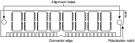
Figure 14 : Cisco 7200 Series Main Memory SIMM
Step 3 Hold the sides of the SIMM between your thumb and middle finger, with your forefinger against the far edge, opposite the connector edge. (See Figure 9.)
Step 4 Tilt the SIMM to approximately the same angle as the socket and insert the entire connector edge into the socket.
 Caution When inserting SIMMs, use firm but not excessive pressure. If you damage a socket, you must return the I/O controller or the network processing engine to the factory for repair.
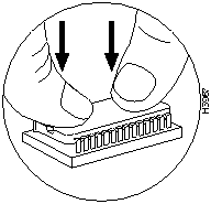
Step 5 Gently push the SIMM into the socket until the spring clips snap over the ends of the SIMM. If necessary, rock the SIMM gently back and forth to seat it properly.
Step 6 Repeat Steps 1 through Step 5 for the remaining SIMMs.
Step 7 When all SIMMs are installed, check all alignment holes (two on each SIMM), and ensure that the spring retainer is visible. If it is not, the SIMM is not seated properly. If any SIMM appears misaligned, carefully remove it and reseat it in the socket. Push the SIMM firmly back into the socket until the retainer springs snap into place.
This completes the SIMM replacement procedure. If you plan to replace the boot ROM, proceed to the following section "Removing the Boot ROM." If you do not plan to replace the boot ROM, proceed to the section "Replacing the Input/Output Controller" later in this document.
Removing the Boot ROM
The ROM monitor is in located in socket U20 on the I/O controller (refer to Figure 5). To remove the boot ROM device, complete the following steps:
Step 1 Attach an ESD-preventive strap between you and any unpainted router surface.
Step 2 Place the I/O controller flat on an antistatic mat or surface and locate the boot ROM device.
Step 3 Carefully remove the new boot ROM from its packaging and verify that the new boot ROM is the correct version for this upgrade. Return the new boot ROM to its packaging.
Step 4 Place the angled tips of the IC removal tool beneath the ends of the boot ROM (refer to Figure 15).
Figure 15 : Enlargement of the IC Removal Tool and Boot ROM
Step 5 Squeeze the arms of the IC removal tool and gently, but firmly, pull up on the boot ROM until its pins are clear of the socket. Apply even pressure to both tips of the IC removal tool (refer to Figure 16). It might be necessary to gently rock the IC removal tool and boot ROM end to end until the boot ROM is free of the socket.
 Caution To prevent bent pins, pull the boot ROM straight up and out of its socket.
Figure 16 : Using the IC Removal Tool to Remove the Boot ROM
Step 6 Set the old boot ROM aside (preferably in an antistatic bag).
This completes the steps for removing the Boot ROM. Proceed to the section "Installing a New Boot ROM."
Installing a New Boot ROM
To install a new Boot ROM, complete the following steps:
Step 1 Remove the new boot ROM device from its packaging.
Step 2 Align the new boot ROM with the U20 socket, and note the notch at the end of the socket and boot ROM. Match the notch at the end of the boot ROM with the notch on the socket. If the boot-ROM notch is not aligned with the socket notch, the boot ROM will be damaged when power is turned on.
Step 3 Applying pressure evenly, gently press the boot ROM's pins into the holes in the U20 socket. (See Figure 17.) Take care not to bend any pins. You can straighten bent pins using small needlenose pliers; however, a broken pin means that the boot ROM is unusable, and you must order a new one.
 Caution To prevent bent pins, push the boot ROM straight down into its socket, applying pressure evenly.
Figure 17 : Inserting the Boot ROM into the Socket
Step 4 When you have inserted the new boot ROM all the way into its socket, check around the boot ROM for any bent pins. Pins bent underneath the boot ROM are difficult to see.
If any pins are bent, remove the boot ROM, use the needlenose pliers to straighten the pins, and reinsert the boot ROM as described in Step 7 through Step 9. Note that a broken pin means that the boot ROM is unusable, and you must order a new one.
If all pins are inserted correctly, and the boot ROM notch is aligned with the socket notch, the boot ROM is properly installed.
This completes the steps for installing a new Boot ROM. Proceed to the section "Replacing the Input/Output Controller."
Replacing the Input/Output Controller
To replace the I/O controller in the router, complete the following steps:
Step 1 Ensure that the router is powered down and its input power cable is disconnected from the router and the power source. Refer to the section "Powering Down the Router and Disconnecting Input Power" earlier in this document.
Step 2 Attach an ESD-preventative wrist strap between you and an unfinished chassis surface.
Step 3 Using both hands, grasp the I/O controller by its metal carrier edges and orient the I/O controller so that its printed circuit board components are upward (refer to Figure 8).
 Caution Handle the I/O controller by the carrier edges and handle only; never touch the printed circuit board components or connector pins.
Step 4 Align the left and right edge of the I/O controller between the I/O controller slot guides (refer to Figure 18).
Figure 18 : Aligning the I/O Controller's Printed Circuit Board between the Slot Guides
 Caution Do not align the I/O controller's metal carrier between the slot guides. Doing so will damage components on the printed circuit board as you slide the I/O controller into its chassis slot.
Step 5 Gently push the I/O controller all the way into its chassis slot until you feel the connectors mate with the router midplane.
Step 6 Seat the I/O controller in the router midplane by tightening its captive installation screws with a number 2 Phillips screwdriver.
Note The I/O controller is not fully seated in the router midplane until you tighten its captive installation screws (use a number 2 Phillips screwdriver).
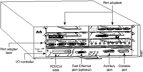
Step 7 Connect the cables to the I/O controller's console, auxiliary, and Fast Ethernet (if present) ports (refer to Figure 19).
Figure 19 : Input/Output Controller Ports, Handle, and Captive Installation Screws
Step 8 Replace Flash memory cards (if present) in the I/O controller's PCMCIA slots. Refer to the section "Installing and Removing a Flash Memory Card" later in this document.
This completes the procedure for replacing the I/O controller in a Cisco 7200 series router. Proceed to the section "Replacing the Network Processing Engine."
Replacing the Network Processing Engine
To replace the network processing engine in the router, complete the following steps:
Step 1 Ensure that the router is powered down and its input power cable is disconnected from the router and the power source. Refer to the section "Powering Down the Router and Disconnecting Input Power" earlier in this document.
Step 2 Attach an ESD-preventative wrist strap between you and an unfinished chassis surface.
Step 3 Using both hands, grasp the network processing engine by its metal carrier edges and orient the network processing engine so that its printed circuit board components are upward (you can see the components) (refer to Figure 8).
 Caution Handle the network processing engine by the carrier edges and handles only; never touch the printed circuit board components or connector pins.
Step 4 Align the left and right edge of the network processing engine's printed circuit board between the network processing engine slot guides (refer to Figure 20).
Figure 20 : Aligning the Network Processing Engine between the Slot Guides
 Caution Do not align the network processing engine's metal carrier between the slot guides. Doing so will damage components on the network processing engine's printed circuit board as you slide the network processing engine into its chassis slot.
Step 5 Gently slide the network processing engine all the way into its chassis slots until you feel the connectors mate with the router midplane.
Step 6 Seat the network processing engine in the router midplane by tightening its captive installation screws with a number 2 Phillips screwdriver.
Note The network processing engine is not fully seated in the router midplane until you tighten its captive installation screws (use number 2 Phillips screwdriver).
Step 7 If you removed power supplies from the router, replace the power supplies. Refer to the section "Removing and Installing an AC-Input Power Supply" on page 28 of this document when replacing an AC-input power supply in a Cisco 7200 series router.
Step 8 If you pushed the front of router out of the rack, slowly guide the router back into the rack.
Step 9 Use a 3/16-inch flat-blade screwdriver to tighten the four screws that secure the router to front mounting strips of the rack.
This completes the procedure for replacing the network processing engine in a Cisco 7200 series router. Proceed to the section "Reconnecting Input Power and Powering Up the Router."
Reconnecting Input Power and Powering Up the Router
The following sections explain how to reconnect AC-input power to a Cisco 7200 series router, power up the router, and verify a successful system boot.
To connect AC-input power to a Cisco 7200 series router, complete the following steps:
Step 1 At the rear of the router, check that the power switch on the power supply is in the OFF (0) position.
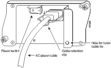
Step 2 Slide the cable-retention clip down, away from the AC receptacle, and plug in the power cable.
Step 3 Secure the cable in the power supply AC receptacle by sliding the cable-retention clip up until it snaps around the connector. The cable-retention clip provides strain relief for the AC power cable (refer to Figure 21).
Figure 21 : Connecting AC-Input Power to a Cisco 7200 Series Router
Step 4 Plug the AC power supply cable into the AC power source.
Note Each AC-input power supply operating at 120 VAC requires a minimum of 5A service. We recommend powering the Cisco 7200 series routers from a 15A receptacle at the power source.
Step 5 Repeat Step 1 through Step 4 for the second power supply (if present).
This completes the steps for connecting input power to a Cisco 7200 series router.
To power up a Cisco 7200 series router that has an installed AC-input power supply, complete the following steps:
Step 1 Check for the following:
- Each port adapter is inserted in its slot and its respective port adapter lever is in the locked position
- The network processing engine and the I/O controller are inserted in their respective slots, and their captive installation screws are tightened
- All network interface cables are connected to the port adapters
- A Flash memory card is installed in its PCMCIA slot (if present)
- Each power cable is connected and secured with the cable-retention clip
- The console terminal is turned on
Step 2 At the rear of the router, place the power switch on the power supply in the ON (|) position. Repeat this step if a second power supply is installed in the router. The green OK LED on the power supply turns on.
Step 3 Listen for the fans; you should immediately hear them operating.
Step 4 During the boot process, observe the system's LEDs. The LEDs on most of the port adapters go on and off in irregular sequence. Some may go on, go out, and go on again for a short time. On the I/O controller, the IO Power OK LED comes on immediately.
Step 5 Observe the initialization process. When the system boot is complete (a few seconds), the network processing engine begins to initialize the port adapters and the I/O controller. During this initialization, the LEDs on each port adapter behave differently (most flash on and off). The enabled LED on each port adapter goes on when initialization is completed, and the console screen displays a script and system banner similar to the following:
Cisco Internetwork Operating System Software
IOS (tm) 7200 Software (C7200-J-M), Version 11.1(6)CA [kpfjrgiu 100]
Copyright (c) 1986-1996 by cisco Systems, Inc.
Compiled Sun 21-Apr-96 04:10 by
If the system fails to boot properly, or if the console terminal displays a checksum or memory error, check the following:
- Ensure that all SIMMs are installed correctly. If necessary, shut down the system and remove the I/O controller or the network processing engine. Check the SIMMs by looking straight down on them and then at eye level. The SIMMs should all be aligned at the same angle and the same height when properly installed. If a SIMM appears to stick out or rest in the socket at a different angle from the others, remove the SIMM and reinsert it. Then replace the I/O controller or the network processing engine and reboot the system for another installation check.
- Each DRAM SIMM bank must contain SIMMs of the same size and speed or the system will not operate. SIMMs must be 60 ns or faster. The speed is silkscreened along one edge of the SIMM.
If after several attempts the system fails to restart properly, contact a service representative for assistance. Before you call, make note of any error messages, unusual LED states, or any other indications that might help solve the problem.
This completes the procedures for reconnecting input power and powering up the router. This also completes the procedure for removing and replacing memory SIMMs and the ROM monitor device for the Cisco 7200 series routers.
Installing and Removing a Flash Memory Card
The I/O controller has two PCMCIA slots: Slot 0 (lower) and Slot 1 (upper). (See Figure 22) To install a Flash memory card in either PCMCIA slot, complete the following steps:
Step 1 Connect an ESD-preventive strap between you and an unpainted chassis surface.
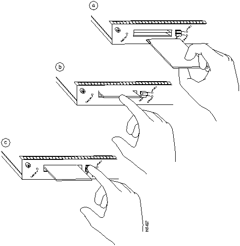
Step 2 Orient the Flash memory card so that its connector end faces the appropriate slot (refer to Figure 22a).
Step 3 Carefully guide the card into the slot until it mates with the slot's connector and the eject button for the slot pops out toward you (See Figure 22b).
Note Flash memory cards do not insert all the way into the PCMCIA slots on the I/O controller; the end of the card protrudes from the I/O controller faceplate. Do not attempt to force the card past this point.
To remove a Flash memory card from either PCMCIA slot, complete the following steps:
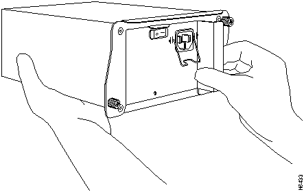
Step 1 Press the ejector button on the slot. (See Figure 22c).
Step 2 Grasp the card and pull it from the slot.
Step 3 Place the card in an antistatic bag.
Figure 22 : Installing and Removing a Flash Memory Card
Removing and Installing an AC-Input Power Supply
The weight of power supplies installed in a Cisco 7200 series router might make it difficult for you to pull the network processing engine from its chassis slot. If this is the case, consider removing installed power supplies from the chassis and then removing the network processing engine. The following sections explain how remove and install an AC-input power supply in a Cisco 7200 series router.
Removing an AC-Input Power Supply from a Cisco 7200 Series Router
To remove an AC-input power supply from a Cisco 7200 series router, complete the following steps:
Step 1 Ensure that the power switch on the power supply is in the OFF (0) position and input power is disconnected from the power supply and its power source. (Refer to the section "Powering Down the Router and Disconnecting Input Power" earlier in this document.)
Step 2 Using a number 2 Phillips screwdriver, loosen the two captive screws on the faceplate of the power supply (refer to Figure 23).
- If the router is not installed in a standard 19-inch rack or in a Telco rack, skip to Step 6. If the router is installed in a rack, determine if any permanent rack fixtures, such as a power strip, are obstructing access to the power supply. If a rack fixture is obstructing access to the power supply, proceed to Step 3.
Figure 23 : AC-Input Power Supply Captive Installation Screws and Handle
Step 3 Using a 3/16-inch flat-blade screwdriver, loosen the screws that secure the router to the front mounting strips of the rack.
Step 4 Position at least one person in front of the rack to support the front underside of the router.
Step 5 From the rear of the rack, carefully push the front of the router out of the rack until there is enough clearance to remove the power supply.
Step 6 Grasp the power supply handle and pull the power supply from the router.
 Caution To maintain agency compliance requirements and meet EMI emissions standards for the Cisco 7200 series chassis with a single power supply, the power supply filler plate must remain in the power supply bay adjacent to the installed power supply. Do not remove this filler plate from the router unless you intend to install a redundant power supply.
Step 7 Repeat Step 1 through Step 6 for the other installed power supply (if present).
This completes the procedure for removing an AC-input power supply from a Cisco 7200 series router. Proceed to the following section "Installing an AC-Input Power Supply."
Installing an AC-Input Power Supply
To install an AC-input power supply in a Cisco 7200 series router, complete the following steps:
Step 1 Make sure the power switch on the power supply is in the OFF (0) position (refer to Figure 10).
Step 2 Grasp the power supply handle with one hand and place your other hand underneath the power supply for support (refer to Figure 24).
Figure 24 : Holding the AC-Input Power Supply
Step 3 Align the power supply to the power supply bay.
Step 4 Slide the power supply completely into the power supply bay until its faceplate is flush with the router's rear panel.
 Caution When inserting a power supply into the router, do not use unnecessary force; slamming the power supply into the bay can damage the connectors on the rear of the supply and on the midplane.
Step 5 Seat the power supply in the router by tightening its captive screws with a number 2 Phillips screwdriver.
Note The power supply is not fully seated in the router midplane until you tighten its captive installation screws (use a number 2 Phillips screwdriver).
Step 6 Repeat Step 1 through Step 5 for a second power supply (if present).
Step 7 If there is no second power supply, replace the filler plate on the empty power supply bay. Using a number 2 Phillips screwdriver, tighten the filler plate's captive screws.
Step 8 If you pushed the router out of the rack, slowly guide the router back into the rack.
Step 9 Use a 3/16-inch flat-blade screwdriver to tighten the screws that secure the router to front mounting strips of the rack.
 Caution To maintain agency compliance requirements and meet EMI emissions standards for the Cisco 7200 series routers with a single power supply, the power supply filler plate must remain in the power supply bay adjacent to the installed power supply. Do not remove this filler plate from the router unless you intend to install a redundant power supply.
This completes the procedures for replacing an AC-input power supply in a Cisco 7200 series router.
Cisco Connection Online
Copyright 1988-1996 © Cisco Systems Inc.