|
|

Cisco 7200 Series Input/Output Controller Replacement Instructions
Product Numbers: C7200-I/O-FE-MII=, C7200-I/O=
This document explains how to remove and replace the Input/Output (I/O) controller in the Cisco 7200 series routers. It includes instructions for powering down a router, removing an installed I/O controller, and installing a new I/O controller in the router. This document also includes steps for verifying the initialization of the installed I/O controller after you power up the router.
The following sections are included in this document:
The Cisco Internetwork Operating System (Cisco IOS) software running your router contains extensive features and functionality. The effective use of many of these features is easier if you have more information at hand.
Cisco documentation and additional literature are available on a CD-ROM called Cisco Connection Documentation, Enterprise Series, which ships with your chassis. The CD is updated and shipped monthly, so it might be more up to date than printed documentation. To order additional copies of the Cisco Connection Documentation, Enterprise Series CD, contact a Cisco Sales or Customer Service representative. You can also access Cisco technical documentation on the World Wide Web URL http://www.cisco.com.
For additional information on configuring the Cisco 7200 series routers, the following documentation resources are available to you:
The following sections give brief overviews of the Cisco 7200 series routers and the I/O controllers.
The Cisco 7200 series consists of the four-slot Cisco 7204 and the six-slot Cisco 7206. The Cisco 7200 series routers support multiprotocol, multimedia routing and bridging with a wide variety of protocols and any combination of Ethernet, Fast Ethernet, Token Ring, Fiber Distributed Data Interface (FDDI), and serial media. Network interfaces reside on port adapters that provide a connection between the routers' three Peripheral Component Interconnect (PCI) buses and external networks. Port adapters can be placed in any available port adapter slot, in any desired combination.
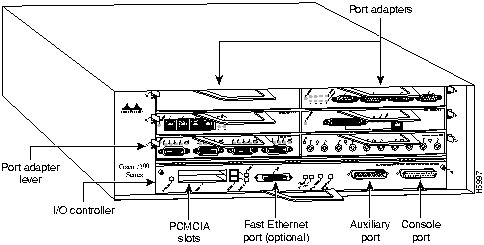
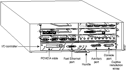
The front of the Cisco 7200 series routers provides access to an Input/Output (I/O) controller and up to four or six network interface port adapters. The I/O controller has a local console port for connecting a data terminal (or data terminal equipment [DTE]) and an auxiliary port for connecting a modem (or other data communications equipment [DCE]) or other devices for configuring and managing the router; two Personal Computer Memory Card International Association (PCMCIA) slots for Flash memory cards; and an optional Fast Ethernet port. The Fast Ethernet port provides a 100-Mbps connection to the network. Figure 1 shows the Cisco 7204. Figure 2 shows the Cisco 7206.
Figure 1 : Cisco 7204---Front View
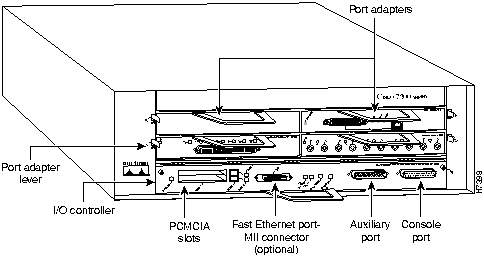
Figure 2 : Cisco 7206---Front View
The port adapters installed in the Cisco 7200 series routers are of the same type as those installed on the second-generation Versatile Interface Processors (VIP2s) in the Cisco 7000 family routers. The port adapters installed in the Cisco 7200 series routers support online insertion and removal (OIR).
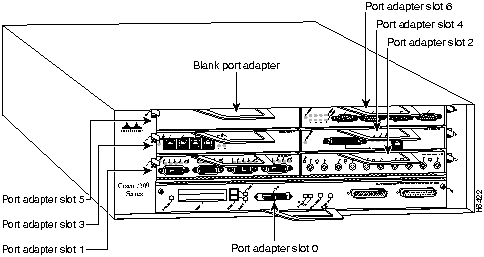
Port adapter slots in the Cisco 7200 series are numbered from left to right, beginning with port adapter slot 1 and continuing through port adapter slot 4 for the Cisco 7204, and slot 6 for the Cisco 7206. Port adapter slot 0 is the Fast Ethernet port on the I/O controller. Figure 3 shows the port adapter slot numbering for the Cisco 7206.
Figure 3 : Port Adapter Slot Numbering---Cisco 7206 Shown
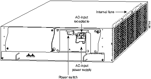
The rear of the Cisco 7200 series routers provides access to the network processing engine and up to two 280W, AC-input or DC-input power supplies (refer to Figure 4).
Figure 4 : Cisco 7200 Series Router---Rear View
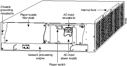
The network processing engine has no external connectors or LEDs. There are two handles for removing and installing the network processing engine and two captive installation screws for securing it to the chassis.
A fully configured Cisco 7200 series router operates with only one installed power supply; however, a second, optional power supply provides hot-swappable, load-sharing, redundant power. The power supply has the router's main power switch and either an AC-input power receptacle, or a hardwired DC-input power cable (depending on the type of installed power supply). Adjacent to the power supply bays there is a 10 x 32-inch chassis ground receptacle that provides a chassis ground connection for ESD equipment or a grounding wire (refer to Figure 4).
Three internal fans draw cooling air into the chassis interior and across internal components to maintain an acceptable operating temperature (refer to Figure 4). The three fans are enclosed in a tray that is located in the subchassis.
The I/O controller, port adapters, power supplies, and network processing engine slide into their respective chassis slots and connect directly to the router's midplane; there are no internal cables to connect. The midplane distributes DC power from the power supplies to the I/O controller, port adapters, fan tray, and network processing engine.
Input/Output Controller Overview
The Input/Output controller shares the system memory functions and the environmental monitoring functions for the Cisco 7200 series routers with the network processing engine.
The I/O controller is available with an optional Fast Ethernet port. Figure 5 shows an I/O controller without the Fast Ethernet port. Figure 6 shows an I/O controller with the Fast Ethernet port. The I/O controller consists of the following components:
Figure 5 : Input/Output Controller---Without the Fast Ethernet Port
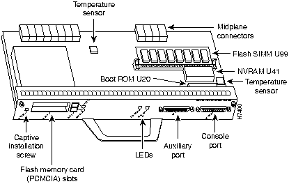
Figure 6 : Input/Output Controller---With the Fast Ethernet Port
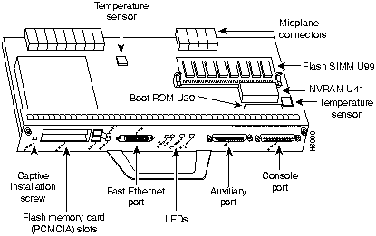
Table 1 lists the I/O controller memory components.
Table 1 : Input/Output Controller Memory Components
| Type | Size | Quantity | Description | Location |
|---|---|---|---|---|
| Boot ROM | 256 KB | 1 | EPROM for the ROM monitor program | Socket U20 |
| Flash SIMM
Flash memory card |
4 MB
8 MB to 20 MB |
1
Up to 2 |
Contains the default boot helper image
Contains the default Cisco IOS image |
Socket U99
PCMCIA Slot 0 and slot 1 |
| NVRAM | 128 KB | 1 | Nonvolatile EPROM for the system configuration file | Socket U41 |
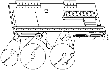
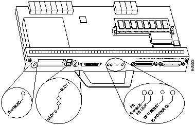
Depending on whether the Fast Ethernet port is present, either two or four LEDs on the I/O controller faceplate indicate system status; two additional LEDs indicate the status of the Flash memory cards installed in either PCMCIA slot.
Figure 7 shows the LEDs of an I/O controller that does not have the Fast Ethernet port. Figure 8 shows the LEDs of an I/O controller that has the Fast Ethernet port. Table 2 lists I/O controller LEDs and their functions.
Next to the IO power OK LED on the I/O controller faceplate is the CPU reset button. The CPU reset button resets the entire system.
Figure 7 : I/O Controller LEDs and CPU Reset Button---Without the Fast Ethernet Port
Figure 8 : I/O Controller LEDs and CPU Reset Button---With the Fast Ethernet Port
This section provides a list of parts and tools you need to remove and replace the I/O controller in the Cisco 7200 series routers. This section also includes safety and ESD-prevention guidelines to help you avoid injury to yourself and damage to the equipment.
You need the following tools and parts to remove and replace the I/O controller. If you need additional equipment, contact a service representative for ordering information:
Following are safety guidelines that you should follow when working with any equipment that connects to electrical power or telephone wiring.
Electrical Equipment Guidelines
Follow these basic guidelines when working with any electrical equipment:
Use the following guidelines when working with any equipment that is connected to telephone wiring or to other network cabling:
Preventing Electrostatic Discharge Damage
Electrostatic discharge (ESD) damages equipment and impairs electrical circuitry. ESD occurs when printed circuit boards are improperly handled and results in complete or intermittent failures.
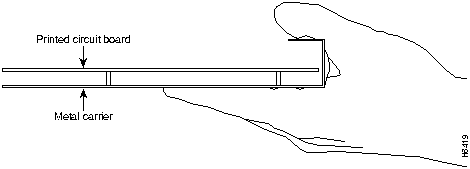
The network processing engine, I/O controller, and port adapters consist of a printed circuit board that is fixed in a metal carrier. Electromagnetic interference (EMI) shielding, connectors, and a handle are integral components of the carrier. Handle the network processing engine, I/O controller, and port adapters by their carrier edges and handle; never touch the printed circuit board or connector pins.
Figure 9 shows the location of a printed circuit board when it is installed in a network processing engine or I/O controller metal carrier. Do not touch the printed circuit board when handling either component.
Figure 9 : Handling the Network Processing Engine and the I/O Controller---Side View
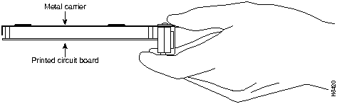
Figure 10 shows the location of a printed circuit board when it is installed in a port adapter metal carrier. Do not touch the printed circuit board when handling a port adapter.
Figure 10 : Handling a Port Adapter---Side View
Although the metal carrier helps to protect the printed circuit boards from ESD, wear a preventive antistatic strap whenever handling the network processing engine, I/O controller, or port adapters. Ensure that the strap makes good skin contact and connect the strap's clip to an unpainted chassis surface to safely channel unwanted ESD voltages to ground.
If no wrist strap is available, ground yourself by touching the metal part of the chassis.
Following are guidelines for preventing ESD damage:
Removing and Replacing the Input/Output Controller
The following sections explain how to remove and replace an I/O controller in the Cisco 7200 series routers. It involves the following tasks:
These tasks are described in detail in the following subsections.
Copying the Configuration File to a TFTP Server
Before you replace the I/O controller, copy the router's running configuration to a Trivial File Transfer Protocol (TFTP) file server so that you can retrieve it later; otherwise, you will have to reenter your configuration manually.
Before copying the router's configuration file to a TFTP file server, check the following items:
Complete the following steps to copy the router's configuration file to a remote host:
This completes the procedure for copying the configuration file to a TFTP server. Proceed to the section "Powering Down the Router and Disconnecting Input Power."
Powering Down the Router and Disconnecting Input Power
To power down a Cisco 7200 series router that has an installed AC-input power supply, complete the following steps:
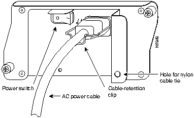
To disconnect AC-input power to a Cisco 7200 series router, complete the following steps:
Figure 11 : Disconnecting Power from a Cisco 7200 Series AC-Input Power Supply
This completes the procedure for powering down the router and disconnecting input power. Proceed to the section "Removing the Input/Output Controller."
Removing the Input/Output Controller
To remove an I/O controller from a Cisco 7200 series router, complete the following steps:
Figure 12 : Cisco 7200 Series Input/Output Controller Ports, Handle, and Captive Screws
This completes the procedure for removing an installed I/O controller. Proceed to the section "Replacing an Input/Output Controller."
Replacing an Input/Output Controller
To install a new I/O controller in the router, complete the following steps:
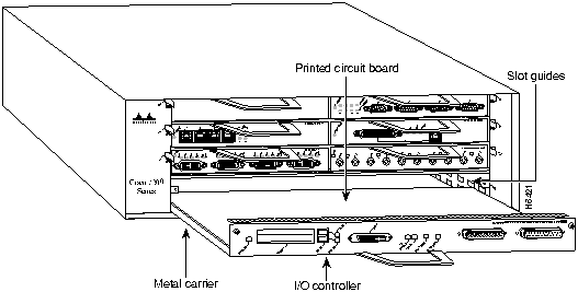
Figure 13 : Aligning the I/O Controller's Printed Circuit Board between the Slot Guides
This completes the procedure for replacing the I/O controller in a Cisco 7200 series router. Proceed to the section "Reconnecting Input Power and Powering Up the Router."
Reconnecting Input Power and Powering Up the Router
The following sections explain how to reconnect AC-input power to a Cisco 7200 series router, power up the router, and verify a successful system boot.
To connect AC-input power to a Cisco 7200 series router, complete the following steps:
Figure 14 : Connecting AC-Input Power to a Cisco 7200 Series Router
This completes the steps for connecting input power to a Cisco 7200 series router. To power up a Cisco 7200 series router that has an installed AC-input power supply, complete the following steps:
This completes the procedures for reconnecting input power and powering up the router. Proceed to the section "Downloading the Saved Configuration from the TFTP Server" later in this document.
Downloading the Saved Configuration from the TFTP Server
After you install a new I/O controller in the router and verify a successful router boot, you must retrieve the router's configuration from the TFTP server and copy it to NVRAM. Use the copy tftp running-config command to copy the saved configuration from the TFTP file server. The system prompts you for a host name and address, the name of the configuration file stored on the host, and confirmation to reboot using the remote file.
Before retrieving the router's configuration file from the TFTP file server, check the following:
To retrieve the saved router configuration from the remote host, complete the following steps:
This completes the procedure for downloading the saved router configuration from the remote host. This also completes the procedure for replacing the I/O controller in a Cisco 7200 series router. Proceed to the following section "Reference Information" for additional information you might need when replacing an I/O controller in a Cisco 7200 series router.
This section includes additional information that you might need when replacing an I/O controller in a Cisco 7200 series router.
I/O Controller Connection Equipment and Port Signaling
This section contains connection equipment and pinout information for the console, auxiliary, and Fast Ethernet ports on the I/O controller.
Fast Ethernet MII Connection Equipment
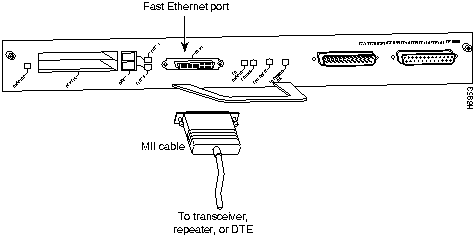
The optional Fast Ethernet port on the I/O controller has a single MII, 40-pin, D-shell type connector that is configurable for 100 megabits per second (Mbps). The MII connector supports IEEE 802.3u interfaces compliant with the 100BASE-X and 100BASE-T standards. The single MII connection requires an external transceiver that permits connection to multimode fiber for 100BASE-FX or 100BASE-T4 physical media (refer to Figure 15).
Figure 15 : Optional Fast Ethernet Port Connection
Depending on the type of media you use between the MII connection and your switch or hub, the network side of your 100BASE-T transceiver should be appropriately equipped with ST-type connectors (for optical fiber), BNC connectors, and so forth.
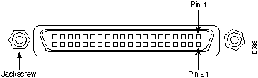
Figure 16 shows the pin orientation of the female MII receptacle on the Fast Ethernet port.
The MII receptacle uses 2-56 screw-type locks, called jackscrews, to secure the cable or transceiver to the MII port. MII cables and transceivers have knurled thumbscrews that you fasten to the jackscrews on the MII connector and tighten with your fingers. Use the jackscrews to secure your MII cable to the MII receptacle.
Table 3 lists the pinouts and signals for the I/O controller MII receptacle.
Table 3 : MII Connector Pinout
Console and Auxiliary Port Connection Equipment
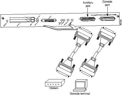
The I/O controller has two EIA/TIA-232 ports: a DCE-mode console port and a DTE-mode auxiliary port. The console port is a DCE DB-25 receptacle for connecting a data terminal. The auxiliary port is a DTE DB-25 plug for connecting a modem or other DCE device (such as a CSU/DSU or other router) to the Cisco 7206 (refer to Figure 17).
Before connecting a terminal to the console port, configure the terminal to match the router console port as follows: 9600 baud, 8 data bits, no parity, 2 stop bits (9600 8N2). You need an EIA/TIA-232 DCE console cable to connect the terminal to the console port. After you establish normal router operation, you can disconnect the terminal.
You must supply your own interface cable between the auxiliary port and the equipment you are connecting. For console and auxiliary port pinouts, refer to the sections "Console Port Signals" and "Auxiliary Port Signals" later in this document.
Figure 17 : Console and Auxiliary Port Connections
Both Data Set ready (DSR) and Data Carrier Detect (DCD) are active when the system is running. The Request To Send (RTS) signal tracks the state of the Clear to Send (CTS) input. The console port does not support modem control or hardware flow control. Table 4 lists the signals used on the console port. The console port requires a straight-through EIA/TIA-232 cable.
Table 4 : Console Port Signals
Table 5 lists the signals used on the auxiliary port. The auxiliary port supports hardware flow control and modem control.
Table 5 : Auxiliary Port Signals
Installing and Removing a Flash Memory Card
The I/O controller has two PCMCIA slots: Slot 0 (lower) and Slot 1 (upper) (refer to Figure 18). To install a Flash memory card in either PCMCIA slot, complete the following steps:
To remove a Flash memory card from either PCMCIA slot, complete the following steps:
Figure 18 : Installing and Removing a Flash Memory Card
Copyright 1988-1996 © Cisco Systems Inc.
![]()
![]()
LED
Function
IO Power OK
Indicates that the I/O controller is on and receiving DC power from the router midplane. This LED comes on during a successful router boot and remains on during normal operation of the router.
Enabled
Indicates that the network processing engine and the I/O controller are enabled for operation by the system; however, it does not mean that the Fast Ethernet port on the I/O controller is functional or enabled. This LED comes on during a successful router boot and remains on during normal operation of the router.
FE ENABLE
Indicates that the Fast Ethernet port on the I/O controller is initialized and enabled for operation by the system. This LED comes on after the I/O controller has been enabled and remains on during normal operation of the router.
FE LINK
Indicates that the Fast Ethernet port on the I/O controller is receiving a carrier signal from the network. This LED remains off during normal operation of the router, unless there is an incoming carrier signal.
Slot 0 Slot 1
The slot 0 and slot 1 LEDs indicate which PCMCIA slot is in use and blink when either slot is being accessed by the system.
![]()
![]()
Router#
copy startup-config tftp
Remote host []?
Router#
copy startup-config tftp
Remote host []?
servername
Translating "servername"...domain server (1.1.1.1) [OK]
Name of configuration file to write [Router-confg]?
Write file Router-confg on host 1.1.1.1? [confirm]
Writing Router-confg .....
Write file Router-confg on host 1.1.1.1? [confirm]
Writing Router-confg: !!!! [ok]
Writing Router-confg .....
![]()
![]()
![]()
Cisco Internetwork Operating System Software
IOS (tm) 7200 Software (C7200-J-M), Version 11.1(6)CA [kpfjrgiu 100]
Copyright (c) 1986-1996 by cisco Systems, Inc.
Compiled Sun 21-Apr-96 04:10 by
Router#
copy tftp running-config
Host or network configuration file [host]?
IP address of remote host [255.255.255.255]?
1.1.1.1
Name of configuration file [router-confg]?
Configure using router-confg from 1.1.1.1? [confirm]
Booting router-confg from 1.1.1.1: ! ! [OK - 874/16000 bytes]
Booting Router-confg ..... [timed out]
![]()
Pin1
In
Out
I/O
Description
14--17
--
Yes
--
Transmit Data (TxD)
12
Yes
--
--
Transmit Clock (Tx_CLK)2
11
--
Yes
--
Transmit Error (Tx_ER)
13
--
Yes
--
Transmit Enable (Tx_EN)
3
--
Yes
--
MII Data Clock (MDC)
4--7
Yes
--
--
Receive Data (RxD)
9
Yes
--
--
Receive Clock (Rx_CLK)2
10
Yes
--
--
Receive Error (Rx_ER)
8
Yes
--
--
Receive Data Valid (Rx_DV)
18
Yes
--
--
Collision (COL)
19
Yes
--
--
Carrier Sense (CRS)
2
--
--
Yes
MII Data Input/Output (MDIO)
22--39
--
--
--
Common (ground)
1, 20, 21, 40
--
--
--
+5.0 volts (V)
1 Any pins not indicated are not used.
2 Tx_CLK and Rx_CLK are provided by the external transceiver.
Pin
Signal
Direction
Description
1
GND
--
Ground
2
TxD
<---
Transmit Data
3
RxD
--->
Receive Data
6
DSR
--->
Data Set Ready (always on)
7
GND
--
Ground
8
DCD
--->
Data Carrier Detect (always on)
Pin
Signal
Direction
Description
2
TxD
--->
Transmit Data
3
RxD
<---
Receive Data
4
RTS
--->
Request To Send (used for hardware flow control)
5
CTS
<---
Clear To Send (used for hardware flow control)
6
DSR
<---
Data Set Ready
7
Signal Ground
--
Signal Ground
8
CD
<---
Carrier Detect (used for modem control)
20
DTR
--->
Data Terminal Ready (used for modem control only)

![]()
![]()
![]()
![]()
![]()
![]()
![]()
![]()