|
|

This chapter provides the following procedures for installing the router, making all external cable connections, turning on the system power, and verifying that the system initializes properly:
The rack-mount kit provides the hardware for mounting the chassis in a standard 19-inch-wide equipment rack or in a Telco-type rack. If you are installing an equipment shelf or using mounting hardware other than that supplied with the chassis, review the guidelines in the section "Equipment Racks" in the chapter "Preparing for Installation," then proceed to the section n "General Installation" in this chapter after the router is installed in the rack. A cable management kit is also included with the chassis. Install these fixtures to keep network interface cables untangled and orderly, and to maintain clear access to interface processors in the lower interface processor slots.
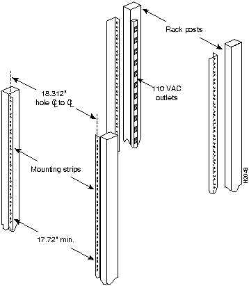
The rack-mounting kit included with the router is for a standard 19-inch, two- or four-post rack or a two-post Telco-type rack. The chassis mounts to two rack posts with ears that attach to the sides of the chassis. The inside width between the two posts or mounting strips (left and right) must be at least 17.72 inches. (See Figure 3-1.) The chassis ears attach to either the front or back of the chassis, so that you can position either the interface processor or noninterface processor end at the front of the rack. Install the cable management fixtures after you install the chassis in the rack.
Some equipment racks provide a power strip along the length of one of the mounting strips. Figure 3-1 shows a typical 19-inch equipment rack with a power strip along one of the back posts. If your rack has this feature, consider the position of the strip when planning fastener points and ensure that you will be able to pull processor modules straight out of the slots. Also, if you plan to install the cable management brackets, ensure that the power strip does not block the sides of the brackets and prevent you from routing the cables through them. When possible, install the interface processor end of the chassis away from the power strip to avoid problems accessing cables and interface processors. (See the section "Equipment Racks" in the chapter "Preparing for Installation.")
The inlet and exhaust ports for cooling air are located in the sides of the chassis, so multiple routers can be stacked in a rack with little or no vertical clearance. If necessary, you can remove the four chassis feet. The chassis is 10.50 inches high when the feet are removed.
Figure 3-1 Typical 19-Inch Equipment Rack Posts and Mounting Strips
Have the following tools on hand before you begin the rack installation:
The rack-mount kit includes the following parts:
When installing the router in an enclosed rack, removing the door temporarily may provide additional clearance. We recommend that you have someone to assist you by supporting the chassis while you mount it in the rack by securing the chassis ears to the rack-mounting strips.
The chassis should be unpacked, and you should have already verified the router configuration.
Each chassis ear has two studs that fit into holes in the chassis. The chassis has two pairs of holes on each side: one pair near the interface processor end and one pair near the noninterface processor end. Both ears must be installed at the same end on each side. Install the ears near the end of the router that will be in the front of the rack. For example, if you plan to install the chassis with the interface processor end of the router at the front and the noninterface processor end in the back of the rack, install the ears near the interface processor end of the chassis. (See Figure 3-2.)
Figure 3-2 Installing the Ears on the Chassis
![]()
To install the ears on the chassis, follow these steps:
![]()
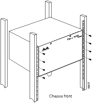
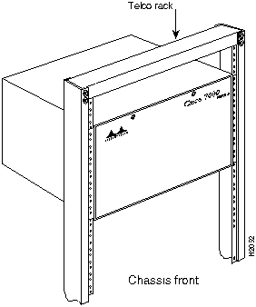
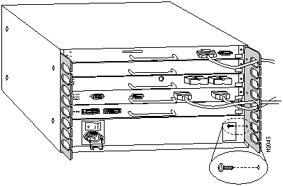
The ears secure the chassis to two rack posts, and the rest of the chassis is cantilevered off the ears. After installing the ears on the chassis, mount the router by securing the ears to two posts or mounting strips in the rack with the eight slotted screws provided. Because the ears bear the weight of the entire chassis, be sure to use all eight slotted screws to fasten the chassis ears to the rack posts. Figure 3-3 shows a typical installation in a standard, 19-inch equipment rack with four mounting posts. Figure 3-4 shows a typical installation in a Telco-type rack, which usually has two center posts and is bolted to the floor. If you are mounting the router in a rack with four posts, use all eight slotted screws to mount the chassis on the front posts.
Figure 3-3 Installing the Chassis in a Four-Post, 19-Inch Rack
We recommend that you allow at least one or two inches of vertical clearance between the router and any equipment directly above and below it. However, if necessary to save vertical space in the rack, you can remove the four chassis feet either before or after you install the chassis in the rack. (It is easier to grip the underside of the chassis to lift it when the feet are in place). Each rubber foot is secured to the chassis bottom with a slotted screw. If removal is necessary, use a 3/16-inch flat-blade screwdriver to remove the feet, then put the feet in a safe place in case you need them later.
Unless you have a way of supporting the chassis in the rack while you install the fasteners, get another person to assist you so that one person can support the chassis while the other installs the fasteners.
![]()
Figure 3-4 Installing the Chassis in a Telco Rack
![]()
To install the chassis in the rack, follow these steps:
![]()
This completes the rack installation. Proceed to the section "Installing the Cable Management Brackets" in this chapter to continue the installation.
The router should already be in the area where you will install it, and your installation location should already be determined; if not, refer to the section "Site Requirements" in the chapter "Preparing for Installation."
When installing the router on a table top, ensure that you have planned a clean, safe location for the chassis and have considered the following:
If you do not mount the router in a rack, follow these steps to install the router on a bench or tabletop:
![]()
The cable management brackets (shown in Figure 3-5) attach to the inner sides of the chassis at the interface processor end. Use the brackets to keep network interface cables untangled and orderly, and to prevent cables from hindering access to interface processors in the lower interface processor slots. Install the brackets before connecting network interface cables to the interface processor ports; otherwise, you will probably need to disconnect the cables to install the screws that secure the brackets. Route interface cables through the cable management brackets as you connect them to the interface processor ports. If necessary, wrap cable ties through the holes provided to secure small-gauge cables.
Figure 3-5 Cable Management Brackets
You will need the following tools and parts to install the cable management brackets; the brackets and panhead screws are included with the chassis:
Follow these steps to install the two cable management brackets on the router:
This completes the cable management bracket installation. Proceed to the next section to connect the interface cables.
Connect an 550W, AC-input power supply as follows:
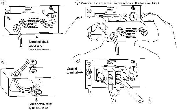
Connect a 600W, DC-input power supply as follows:
![]()
Figure 3-6 Removing and Replacing the Terminal Block Cover and Power Cable Leads
![]()
The following sections describe the basic network connections you will make to the router. Using the Configuration Worksheet will help you to make connections and later configure each interface without having to access the rear of the chassis to check port addresses. We recommend that you complete the "Port Configuration Worksheet" in the chapter "Preparing for Installation" (Table 2-17) if you have not already done so.
The following guidelines will assist you in properly connecting the external network cables to the router interface ports.
![]()
![]()
Have the following tools on hand to secure interface cables and complete the installation:
The sections that follow provide illustrations of the connections between the router interface ports and your network(s). Network interface equipment, such as Ethernet transceivers, MAUs, and CSUs, should be available and in place already. If they are not, refer to the section "Preparing Network Connections" in the chapter "Preparing for Installation" for descriptions of the equipment you need for each interface type to complete the connection to your network.
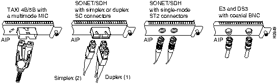
All AIP ATM interfaces are full-duplex. You must use the appropriate ATM interface cable to connect the AIP with an external ATM network. The AIP provides an interface to ATM switching fabrics for transmitting and receiving data up to 155 megabits per second (Mbps) bidirectionally; the actual data rate is determined by the PLIM.
The AIP can support interfaces that connect to the following physical layers:
Connect the AIP interface cables as shown in Figure 3-7. For detailed descriptions of ATM cabling requirements, refer to the section "Distance Limitations" in the chapter "Preparing for Installation" and the section "ATM Connection Equipment" in the chapter "Preparing for Installation."
Figure 3-7 ATM (AIP) Connections
![]()
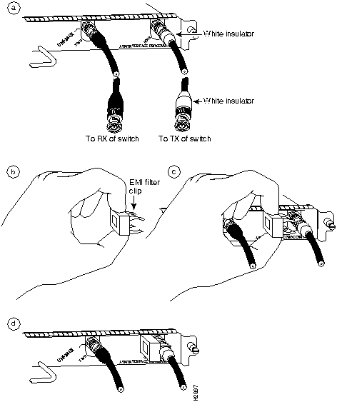
The E3 and DS3 PLIMs require cable CAB-ATM-DS3/E3. If you have an E3 PLIM, you must follow Steps 1 through 3 to install the CAB-ATM-DS3/E3 cable and EMI filter assembly. If you do not have an E3 PLIM, proceed to the appropriate section for your configuration.
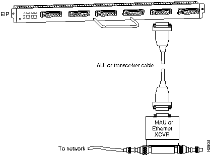
An Ethernet transceiver or MAU should already be connected to your network. Connect each Ethernet port on the EIP to an Ethernet transceiver with a transceiver cable, or to an attachment unit with an attachment unit interface (AUI). Figure 3-9 shows an example of a typical connection. Some transceivers connect directly to the Ethernet port on the EIP (usually the 10BaseT type) and do not require an interface cable.
On each EIP port, slide the metal bracket up over two posts on the cable connector, or tighten the thumbscrews to secure the cable in the port and provide strain relief. For descriptions of the connection equipment and connector locks, refer to the section "Ethernet Connection Equipment" in the chapter "Preparing for Installation."
Figure 3-9 Ethernet Connections
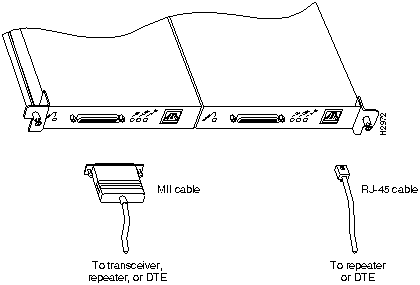
For an MII connection, a 100BaseT transceiver or MAU should already be connected to your network. The RJ-45 connection does not require an external transceiver. On a single 100BaseT port adapter, you can use either the RJ-45 connection or the MII connection. If you have two 100BaseT port adapters on your FEIP, you can use the RJ-45 connection on one and the MII connection on the other. RJ-45 and MII cables are not available from Cisco Systems.
If you have RJ-45 connections, attach the Category 5 UTP cable directly to the RJ-45 port on the FEIP. (See Figure 3-10.) If you have MII connections, attach an MII cable directly to the MII port on the FEIP or attach a 100BaseT or 100BaseF transceiver, with the media appropriate to your application, to the MII port on the FEIP. Attach the network end of your RJ-45 or MII cable to your 100BaseT or 100BaseF transceiver, switch, hub, repeater, DTE, or whatever external 100BaseT equipment you have.
Figure 3-10 Fast Ethernet Connections
![]()
Connecting bus and tag or ESCON cables between the CIP and a host processor is beyond the scope of this publication. The specific CIP connection requirements are discussed in detail in the configuration note Channel Interface Processor (CIP) Installation and Configuration (Document Number 78-1342-xx, where xx is the latest version of the document), which ships with the CIP and is also available on Cisco Connection Documentation CD-ROM.
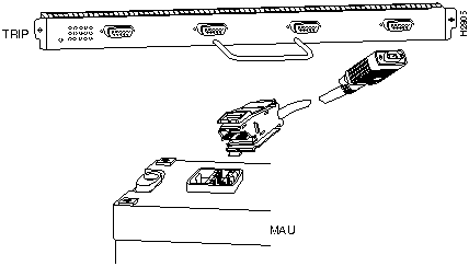
Each Token Ring interface connects to the ring through a MAU or a multistation access unit (MSAU), which should already be connected to the ring. Connect the Type 1 or Type 3 lobe cables to the appropriate TRIP ports and tighten the thumbscrews to secure the cable in the port and provide strain relief. Then connect the network end of each lobe cable to the MAU or MSAU. For descriptions of the connection equipment, refer to the section "Token Ring Connection Equipment" in the chapter "Preparing for Installation."
Figure 3-11 Token Ring Connections
The speed of each Token Ring port must match the speed of the ring to which it is connected. The default speed for all TRIP ports is 4 Mbps, which you can change to 16 Mbps on any port with the configuration command ring-speed n, where n is the speed (4 or 16) in Mbps. Before you enable the Token Ring interfaces, ensure that each is set for the correct speed, or it can bring the ring down. The following sample session changes the ring speed on Token Ring port 1/2 from the default 4 Mbps to 16 Mbps:
7010# configure terminal
int tokenring 1/2
ring-speed 16
^Z
7010# write memory
[OK]
![]()
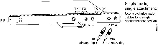
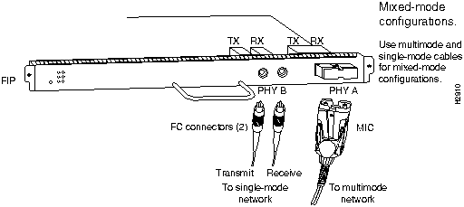
Both single-mode and multimode connections are available and can be combined on one FIP. The fiber-optic cable connects directly to the FIP ports. Single-mode uses separate transmit and receive cables. You will need two single-mode cables for a single-attach connection, or four cables for a dual-attach connection. Multimode uses one integrated transmit/receive cable for each physical interface (one for PHY A and one for PHY B). You will need one multimode cable for a single-attach connection, and two cables for a dual-attach connection. Figure 3-17, which shows the connections for a dual-attach connection that uses both single-mode and multimode fiber, illustrates the types of connections used for both fiber modes. For cable and connector descriptions, refer to the section "FDDI Connection Equipment" in the chapter "Preparing for Installation."
This section also provides instructions for connecting an optical bypass switch to a dual attachment multimode network connection. Because the method of connecting optical bypass switches varies between different manufacturer's models, refer to the documentation for your particular bypass switch for correct connection instructions. If you are installing an optical bypass switch, proceed to the section "Installing an Optical Bypass Switch" in this chapter.
![]()
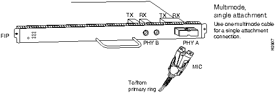
A FIP that is connected as a single-attach station (SAS) typically is connected to the ring through a concentrator. The FIP receives and transmits the signal through the same physical interface, usually PHY A. Depending on whether you are connecting to a single-mode of multimode fiber network, connect the FIP as follows:
Figure 3-12 Single Attach Station (SAS), Single-Mode Fiber Network Connections
If you are connecting other FIPs as dual attach stations (DASs), proceed to the following section. Otherwise, proceed to "Connecting the Console Terminal" in this chapter.
Figure 3-13 Single Attach Station (SAS), Multimode Fiber Network Connections
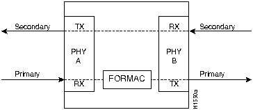
A FIP that is connected as a dual-attach station (DAS) connects to both the primary and secondary rings. The signal for each ring is received on one physical interface (PHY A or PHY B) and transmitted from the other. The standard connection scheme (which is shown in Figure 3-14) for a DAS dictates that the primary ring signal comes into the FIP on the PHY A receive port and returns to the primary ring from the PHY B transmit port. The secondary ring signal comes into the FIP on the PHY B receive port and returns to the secondary ring from the PHY A transmit port. Failure to observe this relationship will prevent the FDDI interface from initializing. Figure 3-17 shows the connections for a dual attachment that uses both multimode and single-mode fiber.
Depending on whether you are connecting to a single-mode or multimode fiber network, connect the FIP as follows:
Figure 3-15 Dual Attach Station (DAS), Single-Mode Fiber Network Connections
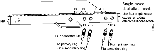
Figure 3-16 Dual Attach Station (DAS), Multimode Fiber Network Connections
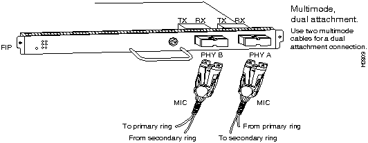
Figure 3-17 FDDI Dual Attach Network Connections, Single-Mode and Multimode
If you are connecting an optical bypass switch, proceed to the next section. Otherwise, proceed to "Connecting the Console Terminal" in this chapter.
An optical bypass switch is a device installed between the ring and the station that provides additional fault tolerance to the network. If a FIP that is connected to a bypass switch fails or shuts down, the bypass switch activates automatically and allows the light signal to pass directly through it, bypassing the FIP completely. (See Figure 3-18 or Figure 3-19.) A port for connecting an optical bypass switch is provided on the multimode/multimode FIP (CX-FIP-MM) and the single-mode/single-mode FIP (CX-FIP-SS).
Figure 3-18 CX-FIP-MM Connection with Optical Bypass
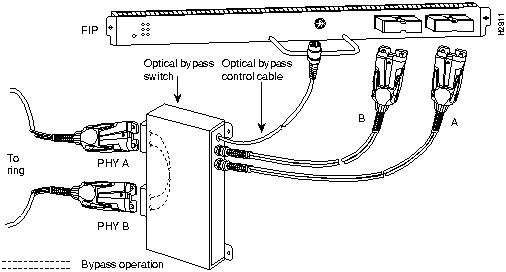
Figure 3-19 CX-FIP-SS Connection with Optical Bypass
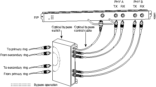
The optical bypass control port on the FIP is a six-pin mini-DIN receptacle. Some optical bypass switches use DIN connectors, and some use a mini-DIN. A DIN-to-mini-DIN control cable (CSB-FMDD) is included with the CX-FIP-MM or CX-FIP-SS to connect optical bypass switches that use the larger DIN connector. Up to 100 milliamperes of current can be supplied to the optical bypass switch.
Following are general instructions for connecting an optical bypass switch to the FIP; however, your particular bypass switch may require a different connection scheme. Use these steps as a general guideline, but refer to the instructions provided by the manufacturer of the switch for specific connection requirements.
All FSIP ports support any available interface type and mode. The serial adapter cable determines the electrical interface type and mode of the port to which it is connected. EIA/TIA-232, EIA/TIA-449, V.35, and X.21 interfaces are available in DTE mode with a plug at the network end and in DCE mode with a receptacle at the network end. EIA-530 is available only in DTE mode with a plug. For descriptions and illustrations of each connector type, refer to the section "Serial Connection Equipment" in the chapter "Preparing for Installation." For cable pinouts, refer to the appendix "Cabling Specifications."
When connecting serial devices, consider the adapter cables as an extension of the router for external connections; therefore, use DTE cables to connect the router to remote DCE devices such as modems or data service units (DSUs), and use DCE cables to connect the router to remote DTE devices such as a host, personal computer (PC), or another router. (See Figure 3-20.) The optional or additional connection equipment required depends on the interface type of each port.
Figure 3-20 Serial Port Adapter Cable Connections
![]()
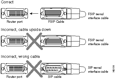
Also, the backshell on the FSIP universal cable connector is not stiff enough to prevent you from inserting the interface cable connector into the FSIP port upside down. Before forcing the cable into the FSIP port receptacle, ensure that the connector is oriented correctly. Forcing a SIP cable into an FSIP port or forcing an FSIP cable into the port upside down can damage the FSIP. (See Figure 3-21.)
Figure 3-21 SIP and FSIP Cables Are Not Interchangeable
A pair of metric thumbscrews is included with each port adapter cable except V.35. If you will connect serial cables to a remote device that uses metric hardware, replace the standard 4-40 thumbscrews at the network end of the cable with the M3 thumbscrews.
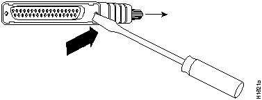
To remove thumbscrews, use the flat side of a large (1/4-inch) flat-blade screwdriver to push the tip of the screw into the connector housing and out the other side. (See Figure 3-22.) If the screw resists, use pliers to pull it out. Insert the new thumbscrew and push it into the connector housing until it pops into place.
Figure 3-22 Replacing Standard 4-40 Thumbscrews with M3 Metric Thumbscrews
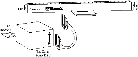
The HIP HSSI port functions as a DTE when it is connected to a DSU for a standard HSSI connection, and it can also be connected to a collocated router with a null modem cable.
To connect the router to a HSSI network, use a HSSI interface cable between the HIP port and the DSU. Both ends of the HSSI interface cable are the same, so you can connect either end to the HIP or DSU. (See Figure 3-23.)
Figure 3-23 HSSI Network Connection
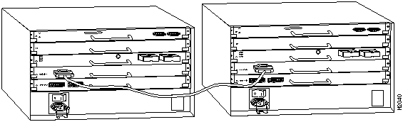
To connect two routers back to back in order to verify the operation of the HSSI port or to build a larger node, use a null modem cable between available HSSI ports in two separate routers. The two routers must be in the same location, and can be two Cisco 7000 series, two AGS+'s, or one of each. When you configure the ports, you must enable the internal transmit clock on in the HSSI interface in both routers with the command hssi internal-clock. To negate the command when you disconnect the cable, use the command no hssi internal-clock. For complete command descriptions and instructions, refer to the related software documentation.
Figure 3-24 HSSI Null Modem Connection
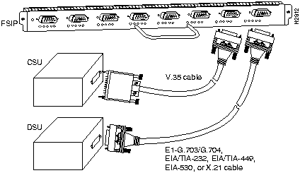
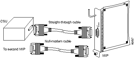
For the MIP, two standard T1 serial cables are available from Cisco Systems and other vendors for use with the MIP: null-modem and straight-through. These interface cables are used to connect your router to external CSUs.
The cables have male 15-pin DB connectors at each end to connect the MIP with the external CSU.
Connect the T1 cable as shown in Figure 3-25.
The system console port on the RP (or RSP7000) is a DCE DB-25 receptacle for connecting a data terminal, which you will need to configure and communicate with your system. The console port is located on the RP (or RSP7000) to the right of the auxiliary port and is labeled Console as shown in Figure 3-26.
Figure 3-26 Console and Auxiliary Port Connections
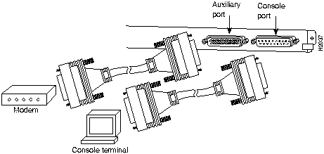
Before connecting the console port, check your terminal's documentation to determine the baud rate of the terminal you will be using. The baud rate of the terminal must match the default baud rate (9600 baud). Set up the terminal as follows: 9600 baud, 8 data bits, no parity, 2 stop bits. Use the console cable provided to connect the terminal to the console port on the RP (or RSP7000), and then follow the steps in the section "Starting the Router" later in this chapter.
The auxiliary port is a DB-25 plug DTE port for connecting a modem or other DCE device (such as a CSU/DSU or other router) to the router. The port is located on the RP (or RSP7000) above the console port and is labeled Auxiliary. An example of a modem connection is shown in Figure 3-26.
When all interfaces are connected, perform a final check of all connections, then power up the router as follows:
        GS Software (GS7), Version 10.3(1)
Copyright (c) 1986-1995 by Cisco Systems, Inc.
Compiled Wed 15-Mar-95 11:06
         --- System Configuration Dialog ---
At any point you may enter a questions mark `?' for help.

Refer to the `Getting Started' Guide for additional help.

Default settings are in square brackets `[]'. continue with

configuration dialog? [yes]:
Many of the interface processor LEDs will not go on until you have configured the interfaces. In order to verify correct operation of each interface, complete the first-time startup procedures and configuration, then refer to the LED descriptions in the appendix "Reading LED Indicators" to check the status of the interfaces.
Your installation is complete. Proceed to the appropriate software configuration publications to configure your interfaces.
This section describes installation, removal, and typical operations of the 8 or 16 MB, Intel Series 2+ Flash memory card, which installs in the PCMCIA slot on the RP faceplate.
The Flash memory card is used to store and boot Cisco Internetwork Operating System (Cisco IOS) software images and interface processor microcode images, and can be used as a server to store software and microcode images for other systems. The Flash memory card is shipped blank; you must format it before using it. Formatting instructions are included in this document.
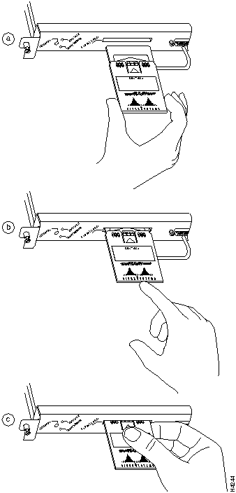
The Flash memory card can be inserted and removed with the power on. Following is the procedure for installing and removing a Flash memory card:
Figure 3-27 Installing the Metal Sleeve
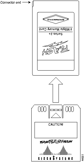
Figure 3-28 Installing and Removing a Flash Memory Card
The Flash memory card shipped with a spare RP or shipped with a system is already formatted. However, a spare Flash memory card is shipped blank and must be reformatted before use. Also, if you plan to use a Flash memory card that was formatted on an RSP-based system (Cisco 7500 series), you must first reformat the card on your system.
![]()
Use the following procedure to format a new Flash memory card:
Router# format slot0:
All sectors will be erased, proceed? [confirm]
Enter volume id (up to 30 characters): MyNewCard
Formatting sector 1
Format device slot0 completed
Router#
The new Flash memory card is now formatted and ready to use.
With the Flash memory card formatted, you can now copy an image into it. To copy an image, use the following procedure, which assumes the following:
Following is the procedure for copying a bootable file (called new.image) into the Flash memory card:
Router> en
Password:
Router# copy tftp:new.image slot0:new.image
20575008 bytes available on device slot0, proceed? [confirm]
Address or name of remote host [1.1.1.1]?
Loading new.image from 1.1.1.1 (via Ethernet1/0): !!!!!!!!!!!!!!!!!!!!!!!!!!!!!!
!!!!!!!!!!!!!!!!!!!!!!!!!!!!!!!!!!!!!!!!!!!!!!!!!!!!!!!!!!!!!!!!!!!!!!!!!!!!!!!!
!!!!!!!!!!!!!!!!!!!!!!!!!!!!!!!!!!!!!!!!!!!!!!!!!!!!!!!!!!!!!!!!!!!!!!!!!!!!!!!!
!!!!!!!!!!!!!!!!!!!!!!!!!!!!!!!!!!!!!!!!!!!!!!!!!!!!!!!!!!!!!!!!!!!!!!!!!!!!!!!!
!!!!!!!!!!!!!!!!!!!!!!!!!!!!!!!!!!!!!!!!!!!!!!!!!!!!!!!!!!!!!!!!!!!!!!!!!!!!!!!!
!!!!!!!!!!!!!!!!!!!!!!!!!!!!!!!!!!!!!!!!!!!!!!!!!!!!!!!!!!!!!!!!!!!!!!!!!!!!!!!!
!!!!!!!!!!!!!!!!!!!!!!!!!!!!!!!!!!!!!!!!!!!!!!!!!!!!!!!!!!!!!!!!!!!!!!!!!!!!!!!!
!!!!!!!!!!!!!!!!!!!!!!!!!!!!!!!!!!!!!!!!!!!!!!!!!!!!!!!!!!!!!!!!!!!!!!!!!!!!!!!!
!!!!!!!!!!!!!!!!!!!!!!!!!!!!!!!!!!!!!!!!!!!!!!!!!!!!!!!!!!!!!!!!!!!!!!!!!!!!!!!!
!!!!!!!!!!!!!!!!!!!!!!!!!!!!!!!!!!!!!!!!!!!!!!!!!!!!!!!!!!!!!!!!!!!!!!!!!!!!!!!!
!!!!!!!!!!!!!!!!!!!!!!!!!!!!!!!!!!!!!!!!!!!!!!!!!!!!!!!!!!!!!!!!!!!!!!!!!!!!!!!!
!!!!!!!!!!!!!!!!!!!!!!!!!!!!!!!!!!!!!!!!!!!!!!!!!!!!!!!!!!!!!!!!!!!!!!!!!!!!!!!!
!!!!!!!!!!!!!!!!!!!!!!!!!!!!!!!!!!!!!!!!!!!!!!!!!!!!!!!!!!!!!!!!!!!!!!!!!!!!!!!!
!!!!!!!!!!!!!!!!!!!!!!!!!!!!!!!!!!!!!!!!!!!!!!!!!!!!!!!!!!!!!!!!!!!!!!!!!!!!!!!!
!!!!!!!!!!!!!!!!!!!!!!!!!!!!!!!!!!!!!!!!!!!!!!!!!!!!!!!!!!!!!!!!!!!!!!!!!!!!!!!!
!!!!!!!!!!!!!!!!!!!!!!!!!!!!!!!!!!!!!!!!!!!!!!!!!!!!!!!!!!!!!!!!!!!!!!!!!!!!!!!!
!!!!!!!!!!!!!!!!!!!!!!!!!!!!!!!!!!!!!!!!!!!!!!!!!!!!!!!!!!!!!!!!!!!!!!!!!!!!!!!!
!!!!!!!!!!!!!!!!!!!!!!!!!!!!!!!!!!!!!!!!!!!!!!!!!!!!!!!!!!!!!!!!!!!!!!!!!!!!!!!!
!!!!!!!!!!!!!!!!!!!!!!!!!!!!!!!!!!!!!!!!!!!!!!!!!!!!!!!!!!!
[OK - 7799951/15599616 bytes]
CCCCCCCCCCCCCCCCCCCCCCCCCCCCCCCCCCCCCCCCCCCCCCCCCCCCCCCCCCCCCCCCCCCCCCCCCCCCCCCC
CCCCCCCCCCCCCCCCCCCCCCCCCCCCCCCCCCCCCCCCCCCCCCCCCCCCCCCCCCCCCCCCCCCCCCCCCCCCCCCC
CCCCCCCCCCCCCCCCCCCCCCCCCCCCCCCCCCCCCCCCCCCCCCCCCCCCCCCCCCCCCCCCCCCCCCCCCC
Router#
Use the following series of commands to make the image (the file named new.image) bootable. Note that, since the configuration register must be set to 0x2102, the config-register command is part of the sequence.
Router# config terminal
Router(config)# no boot system
Router(config)# boot system flash slot0:new.image
Router(config)# config-register 0x2102
Router(config)# ^z
Router# copy running-config startup-config
Router# reload
When the system reloads it will boot the image new.image from the Flash memory card in Slot 0.
To enable booting from Flash memory, set configuration register bits 3, 2, 1, and 0 to a value between 2 and 15 in conjunction with the boot system flash [filename] configuration command.
Following are definitions of the various Flash memory-related boot commands:
boot system flash---Boots the first file in onboard Flash memory
boot system flash herfile---Boots the file named "herfile" on onboard Flash memory
boot system flash slot0:---Boots the first file on Flash memory card in the PCMCIA slot
boot system flash flash:hisfile ---Boots the file named "hisfile" on onboard Flash memory
boot system flash slot0:myfile ---Boots the file named "myfile" on the Flash memory card in the PCMCIA slot
To enter configuration mode and specify a Flash memory filename in the PCMCIA slot from which to boot, enter the configure terminal command at the enable prompt, as follows:
Router# configure terminal
Enter configuration commands, one per line. End with CTRL-Z.
Router(config)# boot system flash slot0:myfile
To disable Break and enable the boot system flash slot0: command, enter the config-register command with the value shown in the following example:
Router(config)# config-reg 0x2102
To exit configuration mode, enter Cntl-Z as follows:
Router(config)# ^Z
Router#
To save the new configuration to memory, use the copy running-config startup-config command as follows:
Router# copy running-config startup-config
Router(config)# boot system flash slot0:myfile         (correct command)
Router(config)# boot system flash slot0: myfile (incorrect command)
In the first case, the router boots the file specified (myfile). In the second case, the router finds the filename field blank, and boots the first file on the Flash memory card.
Copying a new image to Flash memory might be required whenever a new image or maintenance release becomes available. You cannot copy a new image into Flash memory while the system is running from Flash memory.
Use the command copy tftp:filename [ bootflash | slot0]:filename for the copy procedure. Where tftp:filename is the source of the file and [ bootflash | slot0]:filename is the destination in onboard Flash memory or on either of the Flash memory cards.
An example of the copy tftp:filename command follows:
Router# copy tftp:myfile1 slot0:myfile1
20575008 bytes available on device slot0, proceed? [confirm]
Address or name of remote host [1.1.1.1]?
Loading new.image from 1.1.1.1 (via Ethernet1/0): !!!!!!!!!!!!!!!!!!!!!!!!!!!!!!
!!!!!!!!!!!!!!!!!!!!!!!!!!!!!!!!!!!!!!!!!!!!!!!!!!!!!!!!!!!!!!!!!!!!!!!!!!!!!!!!
!!!!!!!!!!!!!!!!!!!!!!!!!!!!!!!!!!!!!!!!!!!!!!!!!!!!!!!!!!!!!!!!!!!!!!!!!!!!!!!!
!!!!!!!!!!!!!!!!!!!!!!!!!!!!!!!!!!!!!!!!!!!!!!!!!!!!!!!!!!!!!!!!!!!!!!!!!!!!!!!!
!!!!!!!!!!!!!!!!!!!!!!!!!!!!!!!!!!!!!!!!!!!!!!!!!!!!!!!!!!!!!!!!!!!!!!!!!!!!!!!!
!!!!!!!!!!!!!!!!!!!!!!!!!!!!!!!!!!!!!!!!!!!!!!![OK - 7799951/15599616 bytes]
CCCCCCCCCCCCCCCCCCCCCCCCCCCCCCCCCCCCCCCCCCCCCCCCCCCCCCCCCCCCCCCCCCCCCCCCCCCCCCCC
CCCCCCCCCCCCCCCCCCCCCCCCCCCCCCCCCCCCCCCCCCCCCCCCCCCCCCCCCCCCCCCCCCCCCCCCCCCCCCCC
CCCCCCCCCCCCCCCCCCCCCCCCCCCCCCCCCCCCCCCCCCCCCCCCCCCCCCCCCCCCCCCCCCCCCCCCCC
Router#
A locked block of Flash memory occurs when power is lost or a Flash memory card is unplugged during a write or erase operation. When a block of Flash memory is locked, it cannot be written to or erased, and the operation will consistently fail at a particular block location. The only way to recover from locked blocks is by reformatting the Flash memory card with the format command.
![]()
For complete command descriptions and configuration information, refer to the Router Products Command Reference publication and the Router Products Configuration Guide.
In order to use the Flash memory card with your RP, the card must have been formatted on an RP. Therefore, if you want to use a card formatted on an RSP (Cisco 7500 series) or an RSP7000, you must first reformat it.
Any Intel Series 2+ Flash memory card can be used with the RP. However, you must install the card's metal sleeve, and the system must contain Cisco IOS Release 11.0 boot ROMs (SWR-G7-11.0.0=). (The RP requires these boot ROMs in order to boot from the Flash memory card.) In addition, the RP can only read up to 16 MB.
|
|
Copyright 1988-1996 © Cisco Systems Inc.