|
|
This appendix is designed to give you a background in internetworking as it applies to the Cisco 700 series routers. This appendix focuses on the internetworking technologies and protocols implemented by these routers.
This appendix contains the following sections:
This section explains basic internetworking concepts. The information presented here helps readers who are new to internetworking understand the technical material in this publication. Sections on the Open System Interconnection (OSI) reference model, important terms and concepts, and key organizations are included.
Moving information between computers of diverse design is a formidable task. In the early 1980s, the International Organization for Standardization (ISO) recognized the need for a network model that would help vendors create interoperable network implementations. The OSI reference model, released in 1984, addresses this need. The OSI reference model quickly became the primary architectural model for intercomputer communications. Although other architectural models (mostly proprietary) have been created, most network vendors relate their network products to the OSI reference model when they want to educate users about their products. So, the model is the best tool available for people hoping to learn about network technology.
The OSI reference model divides the problem of moving information between computers over a network medium into seven smaller and more manageable problems. Each of the seven smaller problems was chosen because it was reasonably self-contained and therefore more easily solved without excessive reliance on external information.
Each of the seven problem areas is solved by a layer of the model. Most network devices implement all seven layers. To streamline operations, however, some network implementations skip one or more layers. The lower two OSI layers are implemented with hardware and software, while the upper five layers are generally implemented in software.
The OSI reference model describes how information makes its way from application programs (such as spreadsheets) through a network medium (such as wires) to another application program in another computer. As the information to be sent descends through the layers of a given system, it looks less and less like human language and more and more like the ones and zeros that a computer processes.
Figure H-1 illustrates how the OSI reference model applies to communication between computers.
Figure H-1 : Communication between Two Computers
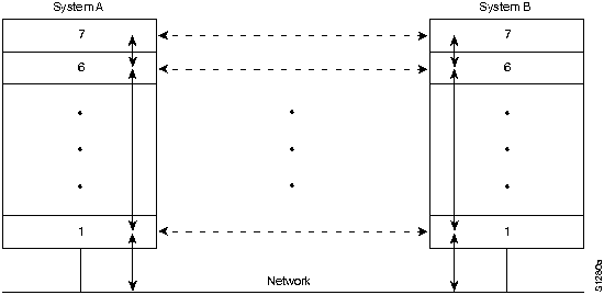
The OSI reference model is not a network implementation. Instead, it specifies the functions of each layer. In this way, it is like a blueprint for the building of a ship. After a ship blueprint is complete, the ship still must be built. Any number of shipbuilding companies can be contracted to do the actual work, just as any number of network vendors can build a protocol implementation from a protocol specification. And, unless the blueprint is extremely (impossibly) comprehensive, ships built by different shipbuilding companies using the same blueprint will differ from each other in at least minor ways. At the very least, for example, it is likely that the rivets will be in different places.
Internetworking, like other sciences, has a terminology and knowledge base all its own. Unfortunately, because the science of internetworking is so young, universal agreement on the meaning of networking concepts and terms has not yet occurred. Definitions of internetworking terms will become more rigidly defined and used as the internetworking industry matures.
For a complete reference to internetworking terms, refer to the Internetworking Terms and Acronyms. This document is located on Cisco Connection Documentation, Enterprise Series, and you can order a printed copy.
Locating computer systems on an internetwork is an essential component of any network system. There are various addressing schemes used for this purpose, depending on the protocol family being used. In other words, AppleTalk addressing is different from TCP/IP addressing, which in turn is different from OSI addressing, and so on.
Two important types of addresses are link-layer addresses and network-layer addresses. Link-layer addresses (also called physical or hardware addresses) are typically unique for each network connection. In fact, for most local-area networks (LANs), link-layer addresses are located in the interface circuitry and are assigned by the organization that defined the protocol standard represented by the interface.
Because most computer systems have one physical network connection, they have only a single link-layer address. Routers and other systems connected to multiple physical networks can have multiple link-layer addresses.
To display your Cisco 700 series router's hardware address, use the show address command. For details about the router software commands, refer to the Cisco 750 Series and Cisco 760 Series Command Reference publication.
As their name implies, link-layer addresses exist at Layer 2 of the OSI reference model. Network-layer addresses (also called virtual or logical addresses) exist at Layer 3 of the OSI reference model. Unlike link-layer addresses, which usually exist within a flat address space, network-layer addresses are usually hierarchical. In other words, they are like mail addresses, which describe a person's location by providing a country, a state, a zip code, a city, a street, an address on the street, and finally, a name. A good example of a flat address space is the U.S. social security numbering system, where each person has a single, unique social security number that identifies that person for taxation and state and federal benefits.
Hierarchical addresses make address sorting and recall easier by eliminating large blocks of logically similar addresses through a series of comparison operations. For example, we can eliminate all other countries if an address specifies the country Ireland. Easy sorting and recall is one reason that routers use network-layer addresses as the basis for routing.
Network-layer addresses differ depending on the protocol family being used, but they typically use similar logical divisions to find computer systems on an internetwork. Some of these logical divisions are based on physical network characteristics (such as the network segment on which system is located); others are based on groupings that have no physical basis (for example, the AppleTalk zone).
After addresses locate computer systems, information can be exchanged between two or more of these systems. Networking literature is inconsistent in naming the logically grouped units of information that move between computer systems. The terms frame, packet, protocol data unit (PDU), segment, message, and others have all been used by those who write protocol specifications.
In this appendix, the term frame denotes an information unit whose source and destination is a link-layer entity. The term packet denotes an information unit whose source and destination is a network-layer entity. Finally, the term message denotes an information unit whose source and destination entity exists above the network layer. Message is also used to refer to particular lower-layer information units that have a specific, well-defined purpose.
Without the services of several key standards organizations, the world of networking would be substantially more chaotic than it is currently. Standards organizations provide forums for discussion, help turn discussion into formal specifications, and proliferate the specifications after they complete the standardization process.
Most standards organizations have specific processes for turning ideas into formal standards. Although these processes differ slightly between standards organizations, they are similar in that they all iterate through several rounds of organizing ideas, discussing the ideas, developing draft standards, voting on all or certain aspects of the standards, and finally formally releasing the completed standards to the public.
Some of the better-known standards organizations follow:
Ethernet was developed by Xerox Corporation's Palo Alto Research Center (PARC) in the 1970s. Ethernet was the technological basis for the IEEE 802.3 specification, which was initially released in 1980. Today, the term Ethernet is often used to refer to all carrier sense multiple access/collision detection (CSMA/CD) LANs that generally conform to Ethernet specifications, including IEEE 802.3.
Ethernet is well suited to applications where a local communication medium must carry sporadic, occasionally heavy traffic at high peak data rates. The Cisco 700 series routers support Ethernet networks.
Ethernet/IEEE 802.3 Comparison
Ethernet and IEEE 802.3 specify similar technologies. Both are CSMA/CD LANs. Stations on a CSMA/CD LAN can access the network at any time. Before sending data, CSMA/CD stations "listen" to the network to see if it is already in use. If it is, the station wanting to transmit waits. If the network is not in use, the station transmits. A collision occurs when two stations listen for network traffic, "hear" none, and transmit simultaneously. In this case, both transmissions are damaged, and the stations must retransmit at some later time.
Backoff algorithms determine when the colliding stations retransmit. CSMA/CD stations can detect collisions, so they know when they must retransmit.
Both Ethernet and IEEE 802.3 LANs are broadcast networks. In other words, all stations see all frames, regardless of whether they represent an intended destination. Each station must examine received frames to determine whether the station is a destination. If so, the frame is passed to a higher protocol layer for appropriate processing.
Typically, the physical manifestation of these protocols is either an interface card in a host computer or circuitry on a primary circuit board within a host computer.
IEEE 802.3 specifies several different physical layers, whereas Ethernet defines only one. Each IEEE 802.3 physical layer protocol has a name that summarizes its characteristics.
Table H-1 lists Ethernet Version 2 and IEEE 802.3 characteristics.
Table H-1 : Ethernet Version 2 and IEEE 802.3 Physical Characteristics
| Characteristic | Ethernet Value |
IEEE 802.3 | Values | |
|---|---|---|---|---|
| 10Base5 | 10Base2 | 10BaseT | ||
| Data rate (Mbps) | 10 | 10 | 10 | 10 |
| Signaling Method | Baseband | Baseband | Baseband | Baseband |
| Maximum segment (m) | 500 | 500 | 185 | 100 |
| Media | 50-ohm coax (thick) | 50-ohm coax (thick) | 50-ohm coax (thin) | Unshielded twisted-pair |
| Topology | Bus | Bus | Bus | Star |
Ethernet is most similar to IEEE 802.3 10Base5. Both of these protocols specify a bus topology network with a connecting cable between the end stations and the actual network medium. In the case of Ethernet, that cable is called a "transceiver cable." The transceiver cable connects to a transceiver device attached to the physical network medium. The IEEE 802.3 configuration is much the same, except that the connecting cable is referred to as an attachment unit interface (AUI), and the transceiver is called a media attachment unit (MAU). In both cases, the connecting cable attaches to an interface board (or interface circuitry) within the end station.
Ethernet and IEEE 802.3 frame formats are shown in Figure H-2.
Figure H-2 : Ethernet and IEEE 802.3 Frame Formats
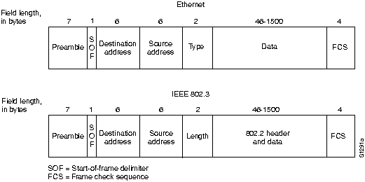
Immediately following the preamble in both Ethernet and IEEE 802.3 LANs are the destination and source address fields. Both Ethernet and IEEE 802.3 addresses are 6 bytes long. Addresses are contained in hardware on the Ethernet and IEEE 802.3 interface cards. The first 3 bytes of the addresses are specified by the IEEE on a vendor-dependent basis, while the last 3 bytes are specified by the Ethernet or IEEE 802.3 vendor. The first 3 bytes of any Cisco 700 series router are 0040f9.
The source address is always a unicast (single node) address, while the destination address might be unicast, multicast (group), or broadcast (all nodes). The router supports bridged filtering of Ethernet frames based on source and destination addresses. For more information on bridge filtering, refer to the section "Transparent Bridging," later in this appendix.
In Ethernet frames, the 2-byte field following the source address is a type field. This field specifies the upper-layer protocol to receive the data after Ethernet processing is complete.
In IEEE 802.3 frames, the 2-byte field following the source address is a length field, which indicates the number of bytes of data that follow this field and precede the frame check sequence (FCS) field.
Following the type/length field is the actual data contained in the frame. After physical-layer and link-layer processing is complete, this data will eventually be sent to an upper-layer protocol. In the case of Ethernet, the upper-layer protocol is identified in the type field.
In the case of IEEE 802.3, the upper-layer protocol must be defined within the data portion of the frame, if at all. If data in the frame is insufficient to fill the frame to its minimum 64-byte size, padding bytes are inserted to ensure at least a 64-byte frame.
Following the data field is a 4-byte FCS field containing a cyclic redundancy check (CRC) value. The CRC is created by the sending device and recalculated by the receiving device to check for damage that might have occurred to the frame in transit.
Integrated Services Digital Network
Integrated Services Digital Network (ISDN) refers to a set of digital services that are becoming available to end users. ISDN involves the digitization of the telephone network so that voice, data, text, graphics, music, video, and other source material can be provided to end users from a single end-user terminal over existing telephone wiring.
Proponents of ISDN imagine a worldwide network much like the present telephone network, except that digital transmission is used, and a variety of new services are available.
ISDN is an effort to standardize subscriber services, user/network interfaces, and network and internetwork capabilities. Standardizing subscriber services attempts to ensure a level of international compatibility.
Standardizing the user/network interface stimulates development and marketing of these interfaces by third-party manufacturers. Standardizing network and internetwork capabilities helps achieve the goal of worldwide connectivity by ensuring that ISDN networks easily communicate with one another.
ISDN applications include high-speed image applications (such as Group IV facsimile), additional telephone lines in homes to serve the telecommuting industry, high-speed file transfer, and video conferencing. Voice, of course, will also be a popular application for ISDN. All of these services are supported by the Cisco 700 series routers.
Many carriers are beginning to offer ISDN under tariff. In North America, large local-exchange carriers (LECs) are beginning to provide ISDN service as an alternative to the T1 connections (digital carrier facilities provided by telephone companies) that currently carry bulk wide-area telephone service (WATS) services.
ISDN components include terminals, terminal adapters (TAs), network-termination devices, line-termination equipment, and exchange-termination equipment. There are two types of ISDN terminals. Specialized ISDN terminals are referred to as "terminal equipment type 1" (TE1). Non-ISDN terminals such as DTE that predate the ISDN standards are referred to as "terminal equipment type 2" (TE2).
TE1s connect to the ISDN network through a four-wire, twisted-pair digital link. TE2s connect to the ISDN network through a terminal adapter.
Beyond the TE1 and TE2 devices, the next connection point in the ISDN network is the network termination type 1 (NT1) or network termination type 2 (NT2) device. These are network-termination devices that connect the four-wire subscriber wiring to the conventional two-wire local loop.
In North America, the NT1 is a customer premises equipment (CPE) device. In most other parts of the world, the NT1 is part of the network provided by the carrier. If you are using the Cisco 751, Cisco 761, or Cisco 765 in North America, you must use an NT1 to connect the router to the ISDN interface. The Cisco 752, Cisco 753, Cisco 762, and Cisco 766 have an integrated NT1, eliminating the need to purchase an additional piece of equipment.
A number of reference points are specified in ISDN. These reference points define logical interfaces between functional groupings such as TAs and NT1s. ISDN reference points include the following:
There are two types of ISDN services: ISDN Basic Rate Interface (BRI) and ISDN Primary Rate Interface (PRI). The Cisco 700 series routers operate with ISDN BRI lines.
The ISDN BRI service offers two B channels and one D channel (2B+D). BRI B-channel service operates at 64 kbps and is meant to carry user data. BRI D-channel service operates at 16 kbps and is meant to carry control and signaling information, although it can support user data transmission under certain circumstances. The D-channel signaling protocol comprises Layers 1 through 3 of the OSI reference model.
BRI also provides for framing control and other overhead, bringing its total bit rate to 192 kbps. The BRI physical layer specification is International Telecommunication Union Telecommunication Standardization Sector (ITU-T) (formerly the Consultative Committee for International Telegraph and Telephone [CCITT]) I.430.
Multiple ISDN user devices can be physically attached to one circuit. In this configuration, collisions can result if two terminals transmit simultaneously. ISDN therefore provides features to determine link contention.
Before ordering your ISDN service to operate with your Cisco 700 series routers, refer to the appendix "Provisioning the ISDN BRI Line for Cisco 700 Series Routers."
Bridges became commercially available in the early 1980s. At the time of their introduction, bridges connected and enabled packet forwarding between homogeneous networks. More recently, bridging between different networks has also been defined and standardized.
Several types of bridging have emerged as important. Transparent bridging is found primarily in Ethernet environments and is the type of bridging supported by the Cisco 700 series routers.
The Cisco 700 series routers bridging functions include sophisticated filtering and high throughput rates. Both bridging and routing have a place in the internetworking world, and both are often necessary in any comprehensive internetworking scheme.
Bridging occurs at the link layer, which controls data flow, handles transmission errors, provides physical (as opposed to logical) addressing, and manages access to the physical medium. Bridges provide these functions by using various link-layer protocols that dictate specific flow control, error handling, addressing, and media-access algorithms.
Bridges are not complicated devices. They analyze incoming frames, make forwarding decisions based on information contained in the frames, and forward the frames toward the destination. The Cisco 700 series routers forward frames one hop at a time toward the destination. For more information on transparent bridging, see the section "Transparent Bridging" later in this appendix.
Upper-layer protocol transparency is a primary advantage of bridging. Because bridges operate at the link layer, they are not required to examine upper-layer information. This means that they can rapidly forward traffic representing any network-layer protocol. It is not uncommon for a bridge to move AppleTalk, DECnet, TCP/IP, Xerox Network Systems (XNS), and other traffic between two or more networks.
The Cisco 700 series routers are capable of filtering frames based on any Layer 2 fields. For example, the router, with bridging functionality enabled, can be configured to reject (not forward) all Ethernet frames of a particular type. Use the set type command to configure this option. For details about the router software commands, refer to the Cisco 750 Series and Cisco 760 Series Command Reference publication.
Because link-layer information often includes a reference to an upper-layer protocol, bridges can usually filter on this parameter. Further, filters can be helpful in dealing with unnecessary broadcast and multicast packets.
By dividing large networks into self-contained units, bridges provide several advantages, including the following:
Bridges can be grouped into categories based on various product characteristics. Using one popular classification scheme, bridges are either local or remote.
Local bridges provide a direct connection between multiple LAN segments in the same area. Remote bridges connect multiple LAN segments in different areas, usually over telecommunications lines. These two configurations are shown in Figure H-3. The Cisco 700 series routers, because they offer an Ethernet and an ISDN port, function as remote bridges.
Figure H-3 : Local and Remote Bridging
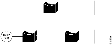
Remote bridging presents several unique internetworking challenges. One of these is the difference between LAN and wide area network (WAN) speeds. Although several fast WAN technologies are now establishing a presence in geographically dispersed internetworks, Ethernet LAN speeds are much faster than ISDN speeds.
Remote bridges cannot improve WAN speeds, but can compensate for speed discrepancies through sufficient buffering capability. If a LAN device capable of a 3-Mbps transmission rate wants to communicate with a device on a remote LAN, the local bridge must regulate the 3-Mbps data stream so that it does not overwhelm the 64-kbps ISDN link. This is done by storing the incoming data in onboard buffers and sending it over the serial link at a rate the serial link can accommodate. This can be achieved only for short bursts of data that do not overwhelm the bridge's buffering capability.
When the bridging functionality is enabled, the Cisco 700 series routers operate as transparent bridges.
Transparent bridges are so named because their presence and operation are transparent to network hosts. When transparent bridges are powered on, they learn the network's topology by analyzing the source address of incoming frames from all attached networks. If, for example, a bridge sees a frame arrive on line 1 from Host A, the bridge concludes that Host A can be reached through the network connected to line 1. Through this process, transparent bridges build a table such as the one in Figure H-4.
Figure H-4 : Transparent Bridging Table
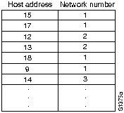
The bridge uses its table as the basis for traffic forwarding. When a frame is received on one of the bridge's interfaces, the bridge looks up the frame's destination address in its internal table. If the table contains an association between the destination address and any of the bridge's ports aside from the one on which the frame was received, the frame is forwarded out the indicated port. If no association is found, the frame is flooded to all ports except the inbound port. Broadcasts and multicasts are also flooded in this way.
Transparent bridges successfully isolate intrasegment traffic, thereby reducing the traffic seen on each individual segment. This usually improves network response times as seen by the user. The extent to which traffic is reduced and response times are improved depends on the volume of intersegment traffic relative to the total traffic and the volume of broadcast and multicast traffic.
The transparent bridge algorithm fails when there are multiple paths of bridges and local-area networks (LANs) between any two LANs in the internetwork.
Figure H-5 illustrates such a bridging loop.
Figure H-5 : Failed Forwarding and Learning in Transparent Bridging Environments
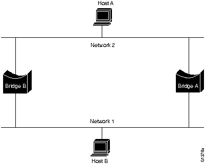
Suppose Host A sends a frame to Host B. Both bridges receive the frame and correctly conclude that Host A is on Network 2. Unfortunately, after Host B receives two copies of Host A's frame, both bridges will again receive the frame on their network 1 interfaces because all hosts receive all messages on broadcast LANs. In some cases, the bridges will then change their internal tables to indicate that Host A is on network 1. If so, when Host B replies to Host A's frame, both bridges will receive and subsequently drop the replies because their tables will indicate that the destination (Host A) is on the same network segment as the frame's source.
In addition to basic connectivity problems such as the one just described, the proliferation of broadcast messages in networks with loops represents a potentially serious network problem. Referring again to Figure H-5, assume that Host A's initial frame is a broadcast. Both bridges will forward the frames endlessly, using all available network bandwidth and blocking the transmission of other packets on both segments.
Because of the problems with network loops, it is important to avoid bridging environments where loops might occur.
Routing is moving information across an internetwork from source to destination. Along the way, at least one intermediate node is typically encountered. Routing is often contrasted with bridging, which seems to accomplish precisely the same thing.
The primary difference between the two is that bridging occurs at Layer 2 (the link layer) of the OSI reference model, while routing occurs at Layer 3 (the network layer). This distinction provides routing and bridging with different information to use in the process of moving information from source to destination. As a result, routing and bridging accomplish their tasks in different ways, and, in fact, there are several different types of routing and bridging. For more information on bridging, refer to the section "Bridging Basics" earlier in this appendix.
The Cisco 700 series routers support routing of Internet Protocol (IP) and Internetwork Exchange Protocol (IPX).
Routing involves two basic activities: determination of optimal routing paths and the transport of information groups (typically called packets) through an internetwork (referred to as switching in this appendix). Switching is relatively straightforward. Path determination, however, can be very complex. For more information on switching, refer to the section "Switching" later in this appendix.
A metric is a standard of measurement---for example, path length---that is used by routing algorithms to determine the optimal path to a destination. To aid the process of path determination, routing algorithms initialize and maintain routing tables, which contain route information. Route information varies depending on the routing algorithm used.
Routing algorithms fill routing tables with a variety of information. Destination/next hop associations tell a router that a particular destination can be reached optimally by sending the packet to a particular router representing the "next hop" on the way to the final destination. When a router receives an incoming packet, it checks the destination address and attempts to associate this address with a next hop. Figure H-6 shows an example of a destination/next hop routing table.
Figure H-6 : Destination/Next Hop Routing Table
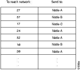
Routing tables can also contain other information, such as information about the desirability of a path. Routers compare metrics to determine optimal routes. Metrics differ depending on the design of the routing algorithm being used. A variety of common metrics will be introduced and described later in this appendix.
Routers communicate with one another (and maintain their routing tables) through the transmission of a variety of messages. The routing update message is one such message. Routing updates generally consist of all or a portion of a routing table. By analyzing routing updates from all routers, a router can build a detailed picture of network topology.
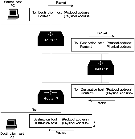
Switching algorithms are relatively simple and are basically the same for most routing protocols. In most cases, a host determines that it must send a packet to another host. Having acquired a router's address by some means, the source host sends a packet addressed specifically to a router's physical (Media Access Control [MAC]-layer) address, but with the protocol (network-layer) address of the destination host.
After examining the packet's destination protocol address, the router determines that it either knows or does not know how to forward the packet to the next hop. If the router does not know how to forward the packet, it typically drops the packet. If the router knows how to forward the packet, it changes the destination physical address to that of the next hop and transmits the packet.
The next hop might or might not be the ultimate destination host. If not, the next hop is usually another router, which executes the same switching decision process. As the packet moves through the internetwork, its physical address changes, but its protocol address remains constant. This process is illustrated in Figure H-7.
Figure H-7 : Switching Process
Routing tables contain information used by switching software to select the best route. Routing algorithms have used many different metrics to determine the best route. Sophisticated routing algorithms can base route selection on multiple metrics, combining them in a single (hybrid) metric. This section describes the different types of metrics used to determine the best route.
Path length is the most common routing metric. Some routing protocols allow network administrators to assign arbitrary costs to each network link. In this case, path length is the sum of the costs associated with each link traversed. Other routing protocols define hop count, a metric that specifies the number of passes through internetworking products (such as routers) that a packet must take on the route from a source to a destination.
Reliability, in the context of routing algorithms, refers to the reliability (usually described in terms of the bit-error rate) of each network link. Some network links might go down more often than others. After going down, some network links might be repaired more easily or more quickly than other links.
Any reliability factors can be taken into account in the assignment of reliability ratings. Reliability ratings are usually assigned to network links by network administrators. They are typically arbitrary numeric values.
Routing delay refers to the length of time required to move a packet from source to destination through the internetwork. Delay depends on many factors, including the bandwidth of intermediate network links, the port queues at each router along the way, network congestion on all intermediate network links, and the physical distance to be traveled. Because it is a conglomeration of several important variables, delay is a common and useful metric.
Bandwidth refers to the available traffic capacity of a link. All other things being equal, a 10-Mbps Ethernet link would be preferable to a 64-kbps leased line. Although bandwidth is a rating of the maximum attainable throughput on a link, routes through links with greater bandwidth do not necessarily provide better routes than routes through slower links. If, for example, a faster link is much busier, the actual time required to send a packet to the destination might be greater through the fast link.
Load refers to the degree to which a network resource (such as a router) is busy. Load can be calculated in a variety of ways, including CPU utilization and packets processed per second. Monitoring these parameters on a continual basis can itself be resource intensive.
Communication cost is another important metric. Some companies might not care about performance as much as they care about operating expenditures. Although line delay might be longer, they will send packets over their own lines rather than through public lines that will cost money for usage time.
Routed versus Routing Protocols
Confusion about the terms routed protocol and routing protocol is common. Routed protocols are protocols that are routed over an internetwork. Examples of such protocols supported by the Cisco 700 series routers are the Internet Protocol (IP) and NetWare's Internetwork Packet Exchange Protocol (IPX).
Routing protocols are protocols that implement routing algorithms. Put simply, they route routed protocols through an internetwork. Examples of these protocols used by the Cisco 700 series routers are Routing Information Protocol (RIP) and Service Advertisement Protocol (SAP). Routed and routing protocols are discussed in the following sections:
In the mid-1970s, the Defense Advanced Research Projects Agency (DARPA) became interested in establishing a packet-switched network to provide communications between research institutions in the United States. DARPA and other government organizations understood the potential of packet-switched technology and were just beginning to face the problem virtually all companies with networks now have---communication between dissimilar computer systems.
With the goal of heterogeneous connectivity in mind, DARPA funded research by Stanford University and Bolt, Beranek, and Newman (BBN) to create a series of communication protocols. The result of this development effort, completed in the late 1970s, was the Internet suite of protocols, of which the Transmission Control Protocol (TCP) and the Internet Protocol (IP) are the two best known.
The Internet protocols can be used to communicate across any set of interconnected networks. They are equally well suited for local-area network (LAN) and wide-area network (WAN) communications. The Internet suite includes not only lower-layer specifications (like TCP and IP), but also specifications for such common applications as electronic mail, terminal emulation, and file transfer.
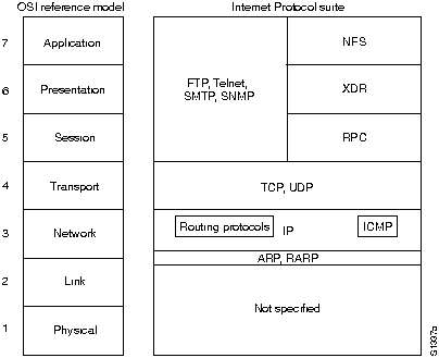
Figure H-8 shows some of the more important Internet protocols and their relationship to the OSI reference model.
Figure H-8 : Internet Protocol Suite and the OSI Reference Model
Creation and documentation of the Internet suite closely resemble an academic research project. The protocols are specified in documents called Request For Comments (RFCs).
RFCs are published and then reviewed and analyzed by the Internet community. Protocol refinements are published in new RFCs. Taken together, the RFCs provide a colorful history of the people, companies, and trends that shaped the development of what is today the world's most popular open-system protocol suite.
IP is the primary Layer 3 protocol in the Internet suite. In addition to internetwork routing, IP provides fragmentation and reassembly of datagrams and error reporting. Along with TCP, IP represents the heart of the IP suite. The IP packet format is shown in Figure H-9.
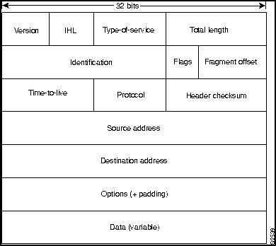
Table H-2 lists the IP packet fields and descriptions.
| Field | Description |
|---|---|
| Version | Version IP currently used. |
| IP header length (IHL) | Indicates datagram header length in 32-bit words. |
| Type-of-service | Specifies how a particular upper-layer protocol would like the current datagram to be handled. Datagrams can be assigned various levels of importance through this field. |
| Total length | Specifies the length of the entire IP packet, including data and header, in bytes. |
| Identification | Contains an integer that identifies the current datagram. This field is used to help piece together datagram fragments. |
| Flags and fragment offset | A 3-bit field of which the low-order 2 bits control fragmentation. One bit specifies whether the packet can be fragmented; the other bit specifies whether the packet is the last fragment in a series of fragmented packets. |
| Time-to-live | Maintains a counter that gradually decrements down to zero, at which point the datagram is discarded. This keeps packets from looping endlessly. |
| Protocol | Indicates which upper-layer protocol receives incoming packets after IP processing is complete. |
| Header checksums | Helps ensure IP header integrity. |
| Source address | Specifies the sending node. |
| Destination address | Specifies the receiving node. |
| Options | Allows IP to support various options, such as security. |
| Data | Contains upper-layer information. |
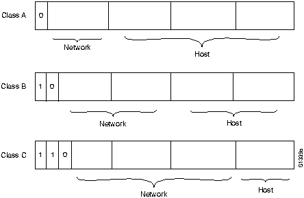
As with all network-layer protocols, the addressing scheme is integral to the process of routing IP datagrams through an internetwork. An IP address is 32 bits in length, divided into either two or three parts. The first part designates the network address; the second part (if present) designates the subnet address; and the final part designates the host address.
Subnet addresses are present only if the network administrator has decided that the network should be divided into subnetworks. The lengths of the network, subnet, and host fields are all variable. IP addressing supports five different network classes. The far-left bits indicate the network class.
IP addresses are written in dotted decimal format. The following is an example of an IP address:
34.10.2.1.Figure H-10 shows the address formats for class A, B, and C IP networks.
Figure H-10 : Class A, B, and C Address Formats
IP networks can also be divided into smaller units, called subnets. Subnets provide extra flexibility for network administrators. For example, assume that a network has been assigned a class B address, and all the nodes on the network currently conform to a class B address format. Then assume that the dotted decimal representation of this network's address is 128.10.0.0. All zeros in the host field of an address specifies the entire network. Rather than change all the addresses to some other basic network number, the administrator can subdivide the network using subnetting. This is done by borrowing bits from the host portion of the address and using them as a subnet field, as shown in Figure H-11.
Figure H-11 : Subnet Addresses
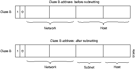
If a network administrator chooses to use 8 bits of subnetting, the third octet of a class B IP address provides the subnet number. For example, address 128.10.1.0 refers to network 128.10, subnet 1; address 128.10.2.0 refers to network 128.10, subnet 2; and so on. The number of bits borrowed for the subnet address is variable.
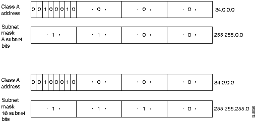
To specify how many bits are used, IP provides the subnet mask. Subnet masks use the same format and representation technique as IP addresses. Subnet masks have ones in all bits except those bits that specify the host field. For example, the subnet mask that specifies 8 bits of subnetting for a class A address 34.0.0.0 is 255.255.0.0. The subnet mask that specifies 16 bits of subnetting for class A address 34.0.0.0 is 255.255.255.0.
Both of these subnet masks are shown in Figure H-12.
Figure H-12 : Sample Subnet Mask
To configure the subnet mask for the connection to a remote device, use the set ip netmask command while in profile mode for that remote device. For details about the router software commands, refer to the Cisco 750 Series and Cisco 760 Series Command Reference publication.
On some media (such as IEEE 802.3 LANs), media addresses and IP addresses are dynamically discovered through the use of two other members of the Internet protocol suite: the Address Resolution Protocol (ARP) and the Reverse Address Resolution Protocol (RARP). ARP uses broadcast messages to determine the hardware Media Access Control (MAC)-layer address corresponding to a particular internetwork address.
ARP is sufficiently generic to allow use of IP with virtually any type of underlying media-access mechanism. RARP uses broadcast messages to determine the Internet address associated with a particular hardware address.
RARP is particularly important to diskless nodes, which might not know their internetwork address when they boot.
Routing devices in the Internet have traditionally been called gateways---an unfortunate term because, elsewhere in the industry, the term applies to a device with somewhat different functionality. Gateways (which we will call routers from this point on) within the Internet are organized hierarchically. Some routers are used to move information through one particular group of networks under the same administrative authority and control (such an entity is called an autonomous system).
Routers used for information exchange within autonomous systems are called interior routers, and they use a variety of interior gateway protocols (IGPs) to accomplish this purpose. Routers that move information between autonomous systems are called exterior routers, and they use an exterior gateway protocol for this purpose.
To configure a static default route to the internal profile's connection interface, use the set gateway command at the system level. For details about the router software commands, refer to the Cisco 750 Series and Cisco 760 Series Command Reference publication.
IP routing protocols are dynamic. Dynamic routing calls for routes to be calculated at regular intervals by software in the routing devices. This contrasts with static routing, where routes are established by the network administrator and do not change until the network administrator changes them. An IP routing table consists of destination address/next hop pairs. A sample entry, shown in Figure H-13, is interpreted as meaning "to get to network 34.1.0.0 (subnet 1 on network 34), the next stop is the node at address 54.34.23.12."
Figure H-13 : IP Routing Table
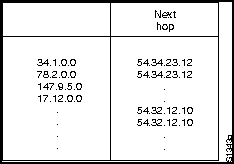
IP routing specifies that IP datagrams travel through internetworks one hop at a time. The entire route is not known at the outset of the journey. Instead, at each stop, the next destination is calculated by matching the destination address within the datagram with an entry in the current node's routing table.
Each node's involvement in the routing process consists only of forwarding packets based on internal information, regardless of whether the packets get to their final destination. In other words, IP does not provide for error reporting back to the source when routing anomalies occur.
The Internet transport layer is implemented by Transmission Control Protocol (TCP) and the User Datagram Protocol (UDP). TCP provides connection-oriented data transport, while UDP operation is connectionless.
TCP provides full-duplex, acknowledged, and flow-controlled service to upper-layer protocols. It moves data in a continuous, unstructured byte stream where bytes are identified by sequence numbers. TCP can also support numerous simultaneous upper-layer conversations. The TCP packet format is shown in Figure H-14.
Figure H-14 : TCP Packet Format
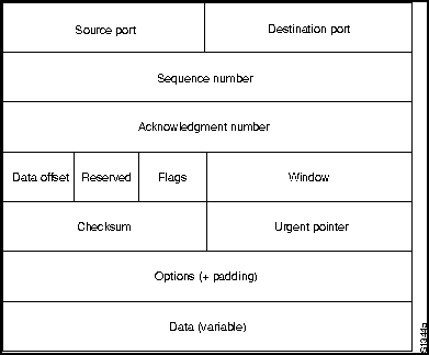
Table H-3 lists the TCP packet fields and descriptions as they appear in Figure H-14.
Table H-3 : TCP Packet Fields Description
| Field | Description |
|---|---|
| Source and destination port | Identifies the points at which upper-layer sources and destination processes receive TCP services. |
| Sequence number | Usually specifies the number assigned to the first byte of data in the current message. Under certain circumstances, it can also be used to identify an initial sequence number to be used in the upcoming transmission. |
| Acknowledgment number | Contains the sequence of numbers of the next byte of data that the sender of the packet expects to receive. |
| Data offset | Indicates the number of 32-bit words in the TCP header. |
| Reserved | Reserved for future use. |
| Flags | Carries a variety of control information. |
| Window | Specifies the size of the sender's receive window (buffer space available for incoming data). |
| Checksum | Indicates whether the header was damaged in transit. |
| Urgent pointer | Points to the first urgent data byte in the packet. |
| Options | Specifies various TCP options. |
| Data | Contains upper-layer information. |
User Datagram Protocol (UDP) is a much simpler protocol than TCP and is useful in situations where the reliability mechanisms of TCP are not necessary. The UDP header has only four fields: source port, destination port, length, and UDP checksum. The source and destination port fields serve the same functions as they do in the TCP header. The length field specifies the length of the UDP header and data, and the checksum field allows packet integrity checking. The UDP checksum is optional.
The Internet suite includes many upper-layer protocols representing a wide variety of applications, including network management, file transfer, distributed file services, terminal emulation, and electronic mail. Table H-4 maps the best-known Internet upper-layer protocols to the applications they support.
Table H-4 : Internet Protocol/Application Mapping
| Application | Protocol |
|---|---|
| File transfer | File Transfer Protocol (FTP) |
| Terminal emulation | Telnet |
| Electronic mail | Simple Mail Transfer Protocol (SMTP) |
| Network management | Simple Network Management Protocol (SNMP) |
| Distributed file services | Network File System (NFS), External Data Representation (XDR), Remote Procedure Call (RPC), X windows |
The Internet suite was designed for communications between two computers using unicast addresses (that is, an address specifying a single network device). To send a message to all devices connected to the network, a single network device uses a broadcast address.
These two forms of addressing have been sufficient for transferring traditional data (such as files and virtual terminal connections). Now that application developers are trying to deliver the same data (such as the audio and video required for conferencing) to some, but not all, devices connected to the network, another form of addressing is required.
The new form of addressing is called multicast addresses. It involves the transmission of a single IP datagram to multiple hosts. This section describes techniques for supporting IP multicast addresses.
Because IP networks tend to have complex topologies with alternate paths built in for redundancy, each technique is evaluated for its ability to deliver data without burdening the network with duplicate packets.
NetWare is a network operating system (NOS) and related support services environment created by Novell, Inc. and introduced to the market in the early 1980s. Then, networks were small and predominantly homogeneous; local-area network (LAN) workgroup communication was new; and the idea of a PC was just becoming popular.
By the early 1990s, NetWare's NOS market share had risen to between 50 and 75 percent. With over 500,000 NetWare networks installed worldwide and an accelerating movement to connect networks to other networks, NetWare and its supporting protocols often coexist on the same physical channel with many other popular protocols, including TCP/IP, DECnet, and AppleTalk.
As a network operating system environment, NetWare specifies the upper five layers of the OSI reference model. It provides file and printer sharing, support for various applications such as electronic mail transfer and database access, and other services. Like other NOSs such as the Network File System (NFS) from Sun Microsystems, Inc. and LAN Manager from Microsoft Corporation, NetWare is based on a client/server architecture. In such architectures, clients (sometimes called workstations) request certain services such as file and printer access from servers.
Originally, NetWare clients were small PCs, while servers were slightly more powerful PCs. As NetWare became more popular, it was ported to other computing platforms. Currently, NetWare clients and servers can be represented by virtually any type of computer system, from PCs to mainframes.
A primary characteristic of the client/server system is that remote access is transparent to the user. This is accomplished through remote procedure calls, a process by which a local computer program running on a client sends a procedure call to a remote server. The server executes the remote procedure call and returns the requested information to the local computer client.
Internet Packet Exchange (IPX) is Novell's original network-layer protocol. When a device to be communicated with is located on a different network, IPX routes the information to the destination through any intermediate networks. Figure H-15 shows the IPX packet format.
Figure H-15 : IPX Packet Format
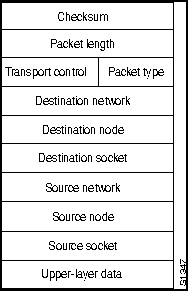
Table H-5 lists the IPX packet fields and descriptions.
Table H-5 : IPX Packet Fields Descriptions
| Field | Description |
|---|---|
| Checksum | A 16-bit field that is set to 1s. |
| Packet length | A 16-bit field that specifies the length, in bytes, of the complete IPX datagram. IPX packets can be any length up to the media maximum transmission unit (MTU) size. There is no packet fragmentation. |
| Transport control | An 8-bit field that indicates the number of routers the packet has passed through. When the value of this field reaches 15, the packet is discarded under the assumption that a routing loop might be occurring. |
| Packet type | An 8-bit field that specifies the upper-layer protocol to receive the packet's information. Two common values for this field are 5, which specifies Sequenced Packet Exchange (SPX), and 17, which specifies the NetWare Core Protocol (NCP). |
| Destination network, destination node, destination socket | Specifies destination information. |
| Source network, source node, source socket | Specifies source information. |
| Upper-layer data | Contains information for upper-layer processes. |
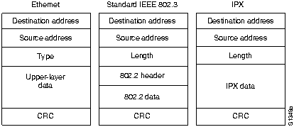
Although IPX was derived from XNS, it has several unique features. From the standpoint of routing, the encapsulation mechanisms of these two protocols are the most important difference. Encapsulation is the process of packaging upper-layer protocol information and data into a frame.
For Ethernet, XNS uses standard Ethernet encapsulation, whereas IPX packets are encapsulated in Ethernet Version 2.0 or IEEE 802.3 without the IEEE 802.2 information that typically accompanies these frames.
Figure H-16 illustrates Ethernet, standard IEEE 802.3, and IPX encapsulation.
Figure H-16 : Ethernet, IEEE 802.3, and IPX Encapsulation Formats
To route packets in an internetwork, IPX uses a dynamic routing protocol called the Routing Information Protocol (RIP). Like XNS, RIP was derived from work done at Xerox for the XNS protocol family. Today, RIP is the most commonly used interior gateway protocol (IGP) in the Internet community, a large international network environment providing connectivity to virtually every research institution, government agency, and university and to many private businesses in the United States and many international organizations. For more detailed information on RIP, see the next section, "Routing Information Protocol."
In addition to the difference in encapsulation mechanisms, Novell also added a protocol called the Service Advertisement Protocol (SAP) to its IPX protocol family. SAP allows nodes that provide services (such as file servers and print servers) to advertise their addresses and the services they provide.
IPX uses 32-bit network numbers to uniquely identify each data link in an IPX internetwork. An example Novell network numbering plan is shown in Figure H-17.
Figure H-17 : IPX Network Numbering Plan
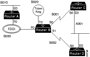
IPX uses a 48-bit address for the node. The IPX device will use the data link address of one interface as its IPX node address. Because the Layer 3 address is the same as the Layer 2 address, there is no need for an Address Resolution Protocol (ARP) process to perform network-to-data link layer address resolution.
The Routing Information Protocol (RIP) is a routing protocol originally designed for Xerox PARC Universal Protocol (where it was called GWINFO) and used in the Xerox Network Systems (XNS) protocol suite. RIP became associated with both UNIX and TCP/IP in 1982 when the Berkeley Software Distribution (BSD) version of UNIX began shipping with a RIP implementation referred to as routed (pronounced "route dee"). RIP, which is still a popular routing protocol in the Internet community, is formally defined in the XNS Internet Transport Protocols publication (1981) and in RFC 1058 (1988).
RIP has been widely adopted by PC manufacturers for use in their networking products. For example, AppleTalk's routing protocol, Routing Table Maintenance Protocol (RTMP), is a modified version of RIP. RIP was also the basis for the routing protocols of Novell, 3Com, UB Networks, and Banyan. The Novell and 3Com RIPs are basically standard Xerox RIP.
Each entry in a RIP routing table provides a variety of information, including the ultimate destination, the next hop on the way to that destination, and a metric. The metric indicates the distance in number of hops to the destination. Other information can also be present in the routing table, including various timers associated with the route. A typical RIP routing table is shown in Figure H-18.
Figure H-18 : Typical RIP Routing Table
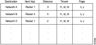
RIP maintains only the best route to a destination. When new information provides a better route, this information replaces old route information. Network topology changes can provoke changes to routes, causing, for example, a new route to become the best route to a particular destination.
When network topology changes occur, they are reflected in routing update messages. For example, when a router detects a link failure or a router failure, it recalculates its routes and sends routing update messages. Each router receiving a routing update message that includes a change updates its tables and propagates the change.
Packet Format: IP Implementations
Figure H-19 shows the RIP packet format for IP implementations, as specified by RFC 1058.
Figure H-19 : RIP Packet Format

Table H-6 lists the RIP packet fields.
Table H-6 : RIP Packet Fields Descriptions
| Field | Description |
|---|---|
| Command | Indicates that the packet is a request or a response. The request command requests the responding system to send all or part of its routing table. Destinations for which a response is requested are listed later in the packet. The response command represents a reply to a request or, more frequently, an unsolicited regular routing update. In the response packet, a responding system includes all or part of its routing table. Regular routing update messages include the entire routing table. |
| Version number | Specifies the RIP version being implemented. With the potential for many RIP implementations in an internetwork, this field can be used to signal different, potentially incompatible, implementations. |
| Address family identifier | Follows a 16-bit field of all zeros and specifies the particular address family being used. On the Internet (a large, international network connecting research institutions, government institutions, universities, and private businesses), this address family is typically IP (value = 2), but other network types might also be represented. |
| Address | Follows another 16-bit field of zeros. In Internet RIP implementations, this field typically contains an IP address. |
| Metric | Follows two more 32-bit fields of zeros and specifies the hop count. The hop count indicates how many internetwork hops (routers) must be traversed before the destination can be reached. |
Up to 25 occurrences of the address family identifier field, address field, and metric field are permitted in any single IP RIP packet. In other words, up to 25 destinations might be listed in any single RIP packet. Multiple RIP packets are used to convey information from larger routing tables.
Like other routing protocols, RIP uses certain timers to regulate its performance. The RIP routing update timer is generally set to 30 seconds, ensuring that each router will send a complete copy of its routing table to all neighbors every 30 seconds. The route invalid timer determines how much time must expire without a router learning about a particular route before that route is considered invalid.
When a route is marked invalid, neighbors are notified of this fact. This notification must occur prior to expiration of the route flush timer. When the route flush timer expires, the route is removed from the routing table. Typical initial values for these timers are 90 seconds for the route invalid timer and 270 seconds for the route flush timer.
The Cisco 700 series routers support RIP routing for both IP and IPX. A useful feature is demand RIP, which enables the user to configure the router to send RIP updates over the ISDN line only when a change occurs in the RIP tables. This minimizes the amount of time that the ISDN line is connected, thereby reducing ISDN usage charges.
Use the set ip rip update or set ipx rip update command to configure when RIP updates will be sent over the ISDN line. For details about the router software commands, refer to the Cisco 750 Series and Cisco 760 Series Command Reference publication.
Simple Network Management Protocol
Simple Network Management Protocol (SNMP) is an application-layer protocol designed to facilitate the exchange of management information between network devices. By using SNMP to access management information data (such as packets per second and network error rates), network administrators can more easily manage network performance and find and solve network problems.
There are two versions of SNMP: Version 1.0, which was the initial version of SNMP, and Version 2.0, which incorporates security features and improvements in protocol operations and management architecture. The Cisco 750 series and Cisco 760 series routers support SNMP v.1, which is discussed later in this section.
In SNMP v.1, agents are software modules that run in managed devices. Agents have access to information about the managed devices in which they run and make this information available to network management systems (NMSs) via SNMP v.1.
This model is graphically represented in Figure H-20.
Figure H-20 : SNMP v.1 Management Model
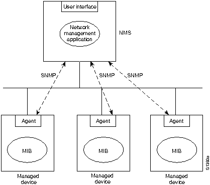
A managed device can be any type of node residing on a network, including computer hosts, communication servers, printers, routers, bridges, and hubs. Because some of these devices might have limited ability to run management software (they might have relatively slow CPUs or limited memory, for example), management software must assume the lowest common denominator. In other words, management software must be built in such a way as to minimize its own performance impact on the managed device.
Because managed devices contain a lowest common denominator of management software, the management burden falls on the NMS. Therefore, NMSs are typically engineering workstation-caliber computers that have fast CPUs, megapixel color displays, substantial memory, and lots of disk space. One or more NMSs can exist on any managed network. NMSs run the network management applications that present management information to users. The user interface is typically based on a standardized graphical user interface (GUI).
To configure when the router will send messages (called traps) to the NMS, use the set snmp trap command. To configure the router with the IP address of the NMS where traps will be sent, use the set snmp trap host command.
The show snmp command displays the router's SNMP configuration.
For details about the router software commands, refer to the Cisco 750 Series and Cisco 760 Series Command Reference publication.
All managed objects are contained in the Management Information Base (MIB), which is essentially a database of objects. For a list of the MIBs supported by the Cisco 700 series routers, see the section "Supported MIBs" in the chapter "Overview of Cisco 700 Series Routers."
The data portion of an SNMP v.1 message contains the specified SNMP v.1 operation (get, set, and so on) and associated operands. Operands indicate the object instances involved in the transaction.
In the late 1980s, the Internet (a large international network connecting many research institutions, government agencies, universities, and private businesses) began to experience explosive growth in the number of hosts supporting the Internet Protocol (IP). The vast majority of these hosts were connected to local-area networks (LANs) of various types, Ethernet being the most common. Most of the other hosts were connected through wide-area networks (WANs) such as X.25-style public data networks (PDNs).
Relatively few of these hosts were connected with simple point-to-point (that is, serial) links. Yet point-to-point links are among the oldest methods of data communications and almost every host supports point-to-point connections. For example, asynchronous EIA/TIA-232-C (formerly RS-232-C) interfaces are essentially ubiquitous. One reason for the small number of point-to-point IP links was the lack of a standard Internet encapsulation protocol. The Point-to-Point Protocol (PPP) was designed to solve this problem.
In addition to solving the problem of standardized Internet encapsulation of IP over point-to-point links, PPP was designed to address other issues, including assignment and management of IP addresses, asynchronous (start/stop) and bit-oriented synchronous encapsulation, network protocol multiplexing, link configuration, link quality testing, error detection, and option negotiation for such capabilities as network-layer address negotiation and data compression negotiation. PPP addresses these issues by providing an extensible Link Control Protocol (LCP) and a family of Network Control Protocols (NCPs) to negotiate optional configuration parameters and facilities.
Today, PPP supports other protocols in addition to IP, including Internetwork Packet Exchange (IPX) and DECnet.
PPP provides a method for transmitting datagrams over serial point-to-point links. It has three main components:
In order to establish communications over a point-to-point link, the originating PPP first sends LCP frames to configure and (optionally) test the data link. After the link is established, and optional facilities are negotiated as needed by the LCP, the originating PPP sends NCP frames to choose and configure one or more network-layer protocols.
When each of the chosen network-layer protocols is configured, packets from each network-layer protocol can be sent over the link. The link will remain configured for communications until explicit LCP or NCP frames close the link, or until some external event occurs (for example, an inactivity timer expires or a user intervenes).
Figure H-21 : PPP Frame Format

Table H-7 describes the PPP frame fields.
| Field | Description |
|---|---|
| Flag | A single byte that indicates the start or end of a frame. The flag field consists of the binary sequence 01111110. |
| Address | A single byte that contains the binary sequence 11111111, the standard broadcast address. PPP does not assign individual station addresses. |
| Control | A single byte that contains the binary sequence 00000011, which calls for transmission of user data in an unsequenced frame. A connectionless link service similar to that of Logical Link Control (LLC) Type 1 is provided. |
| Protocol | 2 bytes that identify the protocol encapsulated in the information field of the frame. The most up-to-date values of the protocol field are specified in the most recent Assigned Numbers Request For Comments (RFCs). |
| Data | Zero or more bytes that contain the datagram for the protocol specified in the protocol field. The end of the information field is found by locating the closing flag sequence and allowing 2 bytes for the FCS field. The default maximum length of the information field is 1,500 bytes. By prior agreement, consenting PPP implementations can use other values for the maximum information field length. |
| Frame Check Sequence (FCS) | Normally 16 bits (2 bytes). By prior agreement, consenting PPP implementations can use a 32-bit (4-byte) FCS for improved error detection. |
The PPP LCP provides a method of establishing, configuring, maintaining, and terminating the point-to-point connection.
PPP provides a method of authentication between two devices that support PPP. Password Authentication Protocol (PAP) and Challenge-Handshake Authentication Protocol (CHAP) enable user identification-password pairs to be sent between two devices. The user identification-password pair is used by one device to authenticate the other before any data is exchanged between them.
This section describes the two authentication methods as implemented by the Cisco 700 series routers.
Configuring the Cisco 700 series routers for PAP authentication requires three steps:
For details about the router software commands, refer to the Cisco 750 Series and Cisco 760 Series Command Reference publication.
Configuring the Cisco 700 series routers for CHAP authentication requires three steps:
For details about the router software commands, refer to the Cisco 750 Series and Cisco 760 Series Command Reference publication.
Copyright 1988-1996 © Cisco Systems Inc.
![]()
![]()
![]()
![]()
![]()
![]()
![]()
![]()