|
|

Troubleshooting the Universal Access Server
This appendix describes how to troubleshoot the access server by referring to the LEDs on the rear panel of the chassis (see Figure 1-2) and on the feature cards. The feature card panels are shown in Figure B-1, Figure B-2, and Figure B-3.
Figure B-1 : T1 PRI Card Panel LEDs
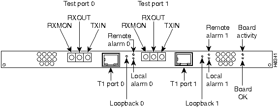
Figure B-2 : E1 PRI Card Panel LEDs
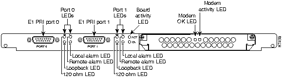
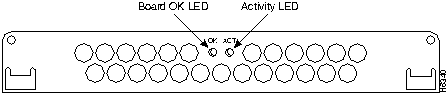
Figure B-3 : 12-Port Modem Card LEDs
The LEDs indicate the current operating condition of the access server. You can observe the LEDs, note any fault condition that the product is encountering, and then contact your system administrator or a customer service representative, if necessary.
Table B-1 : LEDs
| Chassis/Card | LED | State | Description |
|---|---|---|---|
| Access server chassis | Alarm | On | An alarm error has been detected. |
| AUI | Flickering
Off |
The Ethernet LAN connection is transmitting and receiving data normally.
The Ethernet LAN connection is not transmitting or receiving data. Check the Ethernet cable connections. |
|
| Serial | Flickering | The associated serial port connection is transmitting and receiving data normally. | |
| System Status (Located to the right of the Console/Auxiliary ports) | Off
On Blinking |
Power is off or system has not booted.
System is operating normally. A memory failure has occurred. |
|
| Dual T1 PRI card | Activity | Flickering | The CSU/DSU in the card is communicating with a remote CSU/DSU. |
| Board OK | On | The T1 PRI card has passed initial power up diagnostics tests and is operating normally | |
| Loopback | On | A local or remote loopback diagnostic test is running on the associated T1 port. | |
| Remote Alarm | On | A remote alarm indication signal (AIS) has been received on the associated T1 port. The AIS is received on loss of signal (LOS). | |
| Local Alarm | On | The associated T1 port has detected local loss of signal (LOS) or out of frame (OOF) errors. | |
| Dual E1 PRI card | Activity | Flickering | The CSU/DSU in the card is communicating with a remote CSU/DSU. |
| Board OK | On | The E1 PRI card has passed initial power up diagnostics tests and is operating normally | |
| Loopback | On | A local or remote loopback diagnostic test is running on the associated E1 port. | |
| 120 | On | Port is configured for 120 ohm line termination. | |
| Remote Alarm | On | A remote alarm indication signal (AIS) has been received on the associated E1 port. The AIS is received on loss of signal (LOS). | |
| Local Alarm | On | The associated E1 port has detected local loss of signal (LOS) or out of frame (OOF) errors. | |
| 12-Port Modem card | ACT (Activity) | Flickering | The modem card is processing transmit, receive, and modem interrupts normally. |
| OK (Board OK) | On
Off |
The modem card has passed the initial power-up diagnostic tests and is operating normally.
A fault condition is present on the card. |
You can isolate problems on the dual T1 Primary Rate Interface (PRI) card with external test equipment to the RECEIVE jack to monitor signals coming into the RJ-48C port without interrupting normal data transmission. You can use the TRANSMIT jack to inject data, which interrupts normal data transmission.
Troubleshooting Network Interfaces
For information about isolating problems with the network connections to your access server, refer to the publication Troubleshooting Internetworking Systems available on the Cisco Connection Documentation CD-ROM.
For information about technical support, onsite service, and exchange and repair services, refer to the Cisco Information Packet that shipped with the access server.
|
|
Copyright 1988-1996 © Cisco Systems Inc.