Banner
HomeTOCPrevNextGlossSearchHelp

PDF

Table of Contents

1-Port ISDN-BRI WAN Interface Card Configuration Note

1-Port ISDN-BRI WAN Interface Card Configuration Note

1-Port ISDN-BRI WAN Interface Card Configuration Note

Product Numbers:
WIC36-1B-S/T, WIC36-1B-U, CPAWIC36-1B-S/T, CPAWIC36-1B-U

This document provides information about the following Integrated Services Digital Network-Basic Rate Interface (ISDN-BRI) WAN interface cards for the Cisco 3600 series of modular access routers:

Unless specifically identified, references to BRI WAN interface cards in this configuration note include both cards.

Figure 1 : 1-Port ISDN-BRI WAN Interface Card (S/T Interface)

fig_1.gif

Figure 2 : 1-Port ISDN-BRI with NT1 WAN Interface Card (U Interface)

fig_17.gif

A BRI WAN interface card fits into a network module that has slots for WAN cards (called a 2-slot network module or base module). The network module installs in turn into the router chassis. You cannot install a WAN interface card directly into the router chassis.

Use this document in conjunction with your router installation and configuration guide and the Regulatory Compliance and Safety Information document for your router. If you have questions or need help, refer to the section "Obtaining Service and Support" later in this document for further information.

This document contains the following sections:

Warning Only trained and qualified personnel should be allowed to install or replace this equipment. (To see translated versions of this warning, refer to the Regulatory Compliance and Safety Information document that accompanied the router.)

fig_20.gif Warning Before working on a chassis or working near power supplies, unplug the power cord on AC units; disconnect the power at the circuit breaker on DC units. (To see translated versions of this warning, refer to the Regulatory Compliance and Safety Information document that accompanied the router.)

fig_11.gif Warning Ultimate disposal of this product should be handled according to all national laws and regulations. (To see translated versions of this warning, refer to the Regulatory Compliance and Safety Information document that accompanied the router.)

fig_2.gif Caution To avoid damaging electrostatic discharge (ESD)-sensitive components, ensure that you have discharged all static electricity from your body before opening the chassis. Before performing procedures described in this document, review the next section, "Safety Recommendations."


Safety Recommendations

Follow these guidelines to ensure general safety:

Warning The ISDN connection is regarded as a source of voltage that should be inaccessible to user contact. Do not attempt to tamper with or open any public telephone operator (PTO)-provided equipment or connection hardware. Any hardwired connection (other than by a nonremovable, connect-one-time-only plug) must be made only by PTO staff or suitably trained engineers. (To see translated versions of this warning, refer to the Regulatory Compliance and Safety Information document that accompanied the router.)

fig_16.gif Warning Network hazardous voltages are present in the BRI cable. If you detach the BRI cable, detach the end away from the router first to avoid possible electric shock. Network hazardous voltages also are present on the system card in the area of the BRI port (RJ-45 connector), regardless of when power is turned off. (To see translated versions of this warning, refer to the Regulatory Compliance and Safety Information document that accompanied the router.)

fig_5.gif Warning The Ethernet 10BaseT, Token Ring, serial, console, and auxiliary ports contain safety extra-low voltage (SELV) circuits. BRI circuits are treated like telephone-network voltage (TNV) circuits. Avoid connecting SELV circuits to TNV circuits. (To see translated versions of this warning, refer to the Regulatory Compliance and Safety Information document that accompanied the router.)


Safety with Electricity

fig_3.gif Warning Before working on equipment that is connected to power lines, remove jewelry (including rings, necklaces, and watches). Metal objects will heat up when connected to power and ground and can cause serious burns or weld the metal object to the terminals. (To see translated versions of this warning, refer to the Regulatory Compliance and Safety Information document that accompanied the router.)

Follow these guidelines when working on equipment powered by electricity:

Warning Before opening the chassis, disconnect the telephone-network cables to avoid contact with telephone-network voltages. (To see translated versions of this warning, refer to the Regulatory Compliance and Safety Information document that accompanied the router.)

fig_12.gif Warning Do not work on the system or connect or disconnect cables during periods of lightning activity. (To see translated versions of this warning, refer to the Regulatory Compliance and Safety Information document that accompanied the router.)

  • Never assume that power is disconnected from a circuit. Always check.

    fig_13.gif

Warning Do not touch the power supply when the power cord is connected. For systems with a power switch, line voltages are present within the power supply even when the power switch is OFF and the power cord is connected. For systems without a power switch, line voltages are present within the power supply when the power cord is connected. (To see translated versions of this warning, refer to the Regulatory Compliance and Safety Information document that accompanied the router.)

  • Look carefully for possible hazards in your work area, such as moist floors, ungrounded power extension cables, and missing safety grounds.

  • If an electrical accident occurs, proceed as follows:

    • Use caution; do not become a victim yourself.

    • Turn OFF power to the router.

    • If possible, send another person to get medical aid. Otherwise, determine the condition of the victim and then call for help.

    • Determine if the person needs rescue breathing or external cardiac compressions; then take appropriate action.


Preventing Electrostatic Discharge Damage

Electrostatic discharge (ESD) can damage equipment and impair electrical circuitry. It occurs when electronic printed circuit cards are improperly handled and can result in complete or intermittent failures. Always follow ESD prevention procedures when removing and replacing cards. Ensure that the router chassis is electrically connected to earth ground. Wear an ESD-preventive wrist strap, ensuring that it makes good skin contact. Connect the clip to an unpainted surface of the chassis frame to safely channel unwanted ESD voltages to ground. To properly guard against ESD damage and shocks, the wrist strap and cord must operate effectively. If no wrist strap is available, ground yourself by touching the metal part of the chassis.

fig_14.gif Caution For safety, periodically check the resistance value of the antistatic strap, which should be between 1 and 10 megohms (Mohm).


Required Tools and Equipment

You need the following tools and equipment to install a WAN interface card in a Cisco 3600 series router:

  • WAN interface card

  • 2-slot network module

  • Number 1 Phillips screwdriver or small flat-blade screwdriver

  • ESD-preventive wrist strap


WAN Interface Card Slot Assignments

A 2-slot network module for Cisco 3600 series routers has two slots for installing WAN interface cards. These slots are numbered W0, on the right, and W1, on the left. Some WAN interface cards are keyed to be installed in slot W1 only. Cards that do not have a key fit into either slot.

Both BRI WAN interface cards have a key and fit into slot W1 only.


Termination Jumpers

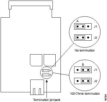
The BRI S/T WAN interface card includes two termination jumpers, labeled J1 and J2. (See Figure 3.) Before installing this card, make sure that these jumpers are set correctly for your installation.

The jumpers are factory-configured in the B position (100 ohms termination). Keep the jumpers in this position to use the BRI S/T WAN interface card in a point-to-point connection or as the last device on the line of a passive-bus connection. Set the termination jumpers to the A position to use the BRI S/T WAN interface card in a passive-bus connection where it is not the last device on the line.

Figure 3 : Termination Jumpers on the BRI S/T WAN Interface Card

h8586.gif


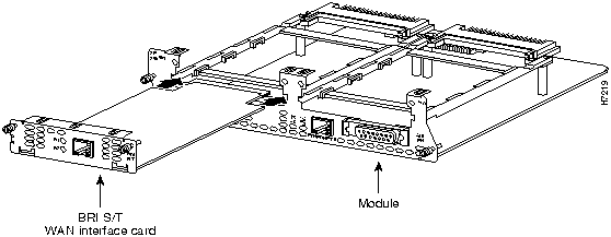
Installing a BRI WAN Interface Card in a Router

fig_7.gif Caution WAN interface cards do not support online insertion and removal (hot swap). Before inserting a WAN interface card into a 2-slot network module that is already installed in the router chassis, you must turn OFF electrical power and disconnect network cables.

The following instructions apply only to installing a WAN interface card in a 2-slot network module. If you need to install the 2-slot module in a chassis slot, see your router installation and configuration guide.

You can install WAN interface cards either before or after mounting the router, whichever is more convenient. You can install the card in the base module either before or after installing the base module in the router chassis.


Note Do not install a BRI WAN interface card in the same chassis as an ISDN Primary Rate Interface (PRI) network module. This configuration is not supported.

Follow this procedure to install the WAN interface card in the 2-slot network module:

Step 1 If the 2-slot network module has already been installed in the router chassis, turn OFF power to the router. However, to channel ESD voltages to ground, do not unplug the power cable. Remove all network interface cables, including telephone cables, from the rear panel.

The following warning applies to routers that use a DC power supply:

fig_8.gif

Warning Before performing any of the following procedures, ensure that power is removed from the DC circuit. To ensure that all power is OFF, locate the circuit breaker on the panel board that services the DC circuit, switch the circuit breaker to the OFF position, and tape the switch handle of the circuit breaker in the OFF position. (To see translated versions of this warning, refer to the Regulatory Compliance and Safety Information document that accompanied the router.)

Step 2 Using either a number 1 Phillips screwdriver or a small flat-blade screwdriver, remove the blank filler panel from the slot in the 2-slot network module where you plan to install the card. Save the blank panel for future use.

Step 3 Align the card with the guides in the 2-slot network module and slide it gently into the WAN interface card slot. (See Figure 4.)

Figure 4 : Installing a BRI WAN Interface Card in a 2-Slot Network Module

h7219.gif

Step 4 Push the card into place until you feel its edge connector mate securely with the connector in the 2-slot network module.

Step 5 Fasten the card's captive mounting screws into the holes in the 2-slot network module faceplate, using the Phillips or flat-blade screwdriver.

Step 6 If the router was previously running, reinstall the network interface cables and turn ON power to the router.

The following warning applies to routers that use a DC power supply:

fig_10.gif

Warning After wiring the DC power supply, remove the tape from the circuit breaker switch handle and reinstate power by moving the handle of the circuit breaker to the ON position. (To see translated versions of this warning, refer to the Regulatory Compliance and Safety Information document that accompanied the router.)


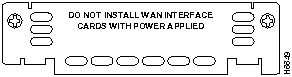
Blank WAN Interface Card Panels

If the 2-slot network module is configured with fewer than two WAN interface cards, make sure that blank panels fill the open base module slots to provide proper airflow. (See Figure 5.)

Figure 5 : Blank WAN Interface Card Panel

h6649.gif


Connecting the WAN Interface Card to the Network

After you install the BRI WAN interface card in the WAN card slot network module and install the network module in the router, use the appropriate cable to connect the BRI card to your WAN.

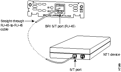
To connect a BRI S/T WAN interface card, use a straight-through RJ-45-to-RJ-45 cable to connect the card's RJ-45 connector to an NT1 device. (See Figure 6.)

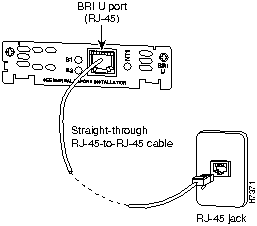
To connect a BRI U WAN interface card, connect a straight-through RJ-45-to-RJ-45 cable directly to your ISDN outlet. (See Figure 7.)

fig_15.gif Caution To prevent damage to the router, make certain you connect the BRI cable to the BRI connector only and not to any other RJ-45 connector.

Figure 6 : Connecting a BRI S/T WAN Interface Card to an NT1

h7369.gif

Figure 7 : Connecting a BRI U WAN Interface Card to an ISDN Outlet

h7371.gif


BRI WAN Interface Card Pinout

Table 1 shows the pinout for the BRI RJ-45 connector.

Table 1 : BRI Port Pinout (RJ-45)

8-Pin1 TE2 NT3 Polarity
3 Transmit Receive +
4 Receive Transmit +
5 Receive Transmit --
6 Transmit Receive --

1 Pins 1, 2, 7, and 8 are not used.
2 TE refers to terminal terminating layer 1 aspects of TE1, TA, and NT2 functional groups.
3 NT refers to network terminating layer 1 aspects of NT1 and NT2 functional groups.


BRI WAN Interface Card LEDs

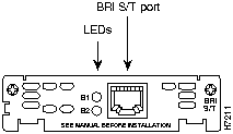
BRI S/T WAN interface cards have two LEDs. These LEDs indicate call activity on the two ISDN-BRI B-channels, as listed in Table 2.

Table 2 : BRI S/T WAN Interface Card LEDs

LED Meaning
B1 Call active on B1 channel
B2 Call active on B2 channel

Figure 8 shows the BRI S/T WAN interface card.

Figure 8 : 1-Port ISDN-BRI WAN Interface Card (S/T Interface)

h7211.gif

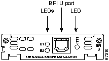
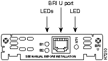
BRI U WAN interface cards have three LEDs. Two of these LEDs indicate call activity on the two ISDN-BRI B-channels, as listed in Table 3. The third LED, labeled NT1, indicates synchronization status of the NT1.

Table 3 : BRI U WAN Interface Card LEDs

LED Meaning
B1 Activity on B1 channel
B2 Activity on B2 channel
NT1 Synchronous status of NT1

Figure 9 shows the BRI U WAN interface card.

Figure 9 : 1-Port ISDN-BRI with NT1 WAN Interface Card (U Interface)

h7210.gif


Configuring the BRI Interface

Whenever you install a new WAN interface card, or if you want to change the configuration of an existing interface, you must configure the interface. If you replace a card that was already configured, the router recognizes it and brings up the interface in the existing configuration.

Before you configure an interface, have the following information available:

  • Protocols you plan to route on the new interface

  • IP addresses, subnet masks, network numbers, zones, or other information related to the routing protocol

    fig_19.gif

Timesaver Obtain this information from your system administrator or network plan before you begin router configuration.

You can configure the new interface and other router parameters by using any of the following methods:

  • Configuration Mode (manual configuration)---Recommended if you are familiar with Cisco Internetwork Operating System (Cisco IOS) commands. Enter the commands at the prompt.

  • AutoInstall---Recommended for automatic installation if another router running Cisco IOS software is installed on the network. This configuration method must be set up by someone with experience using Cisco IOS software.

  • System Configuration Dialog (setup facility)---Recommended if you are not familiar with Cisco IOS commands. You are prompted for each response.

These procedures are explained in the following sections. If you have questions or need help, refer to the section "Obtaining Service and Support" later in this document for further information.

Both configuration mode and the System Configuration Dialog require you to enter the ISDN switch type. These switch types are shown in Table 4.

Table 4 ISDN Switch Types
Country ISDN Switch Type Description
Australia basic-ts013 Australian TS013 switches
Europe basic-1tr6 German 1TR6 ISDN switches
basic-nwnet3 Norwegian NET3 ISDN switches (phase 1)
basic-net3 NET3 ISDN switches (UK and others)
basic-net5 NET5 switches (UK and Europe)
vn2 French VN2 ISDN switches
vn3 French VN3 ISDN switches
Japan ntt Japanese NTT ISDN switches
New Zealand basic-nznet3 New Zealand NET3 switches
North America basic-5ess AT&T basic rate switches
basic-dms100 NT DMS-100 basic rate switches
basic-ni1 National ISDN-1 switches


Configuration Mode

You can configure the BRI interface on your BRI WAN interface card manually, by entering Cisco IOS commands on the command line. This method, called configuration mode, provides the greatest power and flexibility.

Before you begin, disconnect all WAN cables from the router to keep it from trying to run the AutoInstall process. The router tries to run AutoInstall whenever you power it ON if there is a WAN connection on both ends and the router does not have a valid configuration file stored in nonvolative random-access memory (NVRAM) (for instance, when you add a new interface). It can take several minutes for the router to determine that AutoInstall is not connected to a remote Transmission Control Protocol/Internet Protocol (TCP/IP) host.

To enter configuration mode, follow this procedure:

Step 1 Connect a console to the router. If you need instructions for connecting a console, refer to the installation chapter of your router installation and configuration guide. Power up the router.

Step 2 If the current configuration is no longer valid, after about a minute you see the following prompt:


Would you like to enter the initial dialog? [yes]:

Answer no. You now enter the normal operating mode of the router.

If the current configuration is valid, you enter the normal operating mode automatically.

Step 3 After a few seconds you see the user EXEC prompt (Router>). Type enable and the password to enter enable (privileged EXEC) mode:


Router> enable
Password:

Configuration changes can be made only in enable mode. The prompt changes to the privileged EXEC (enable) prompt (Router#):

Router#

Step 4 Enter the command config terminal to enter configuration mode:


Router# config terminal

The router enters global configuration mode, indicated by the Router(config)# prompt.

Step 5 Enter an ISDN switch type from Table 4 earlier in this document, for example:


Router(config)# isdn switch-type basic-5ess

Step 6 If you have not configured the router before, or want to change the configuration, configure global parameters, passwords, network management, and routing protocols. In this example, IP routing, AppleTalk routing, and Internetwork Packet Exchange (IPX) routing are all enabled:


Router(config)# ip routing
Router(config)# appletalk routing
Router(config)# ipx routing

For complete information about global configuration commands, refer to the Cisco IOS configuration guides and command references.

Step 7 Select the BRI interface to configure:


Router(config)# interface bri 0/0
Router(config-if)#

The prompt changes again to show that you are in interface configuration mode.

Step 8 Configure routing protocols on the interface. (You must have previously enabled these protocols as part of global configuration.) In this example, IP, AppleTalk, and IPX are being configured on the BRI interface:


Router(config-if)# ip address 172.16.74.2 255.255.255.0
Router(config-if)# appletalk static cable-range 5-5
Router(config-if)# appletalk zone ZZBRI
Router(config-if)# ipx network B004

Step 9 If your router has more than one BRI interface, enter the exit command to return to the Router(config)# prompt. Repeat Step 7 and Step 8 of this procedure to configure the next BRI interface.

Step 10 By default, the router allocates 25 percent of dynamic random-access memory (DRAM) to shared memory (used for data transmitted or received by network modules and WAN interface cards). If your router includes 16 or more ISDN BRI interfaces, you must increase the amount of shared memory by entering the memory-size iomem command. The following example increases shared memory from 25 percent to 40 percent:


Router(config)# memory-size iomem 40

For further information about the memory-size iomem command, refer to the Cisco IOS configuration guides and command references.

Step 11 When you are finished configuring interfaces, exit configuration mode and return to the enable prompt by pressing Ctrl-Z. To see the current operating configuration, including any changes you just made, enter the show running-config command:


Router# show running-config

To see the configuration currently stored in NVRAM, enter the command show startup-config at the enable prompt.

Router# show startup-config

Step 12 The results of the show running-config and show startup-config commands differ from each other if you have made changes to the configuration, but have not yet written them to NVRAM. To write your changes to NVRAM, making them permanent, enter the command copy running-config startup-config at the enable prompt:


Router# copy running-config startup-config
Building configuration. . .
[OK]
Router#

The router is now configured to boot in the new configuration.


AutoInstall

The AutoInstall process is designed to configure the router automatically after it connects to your WAN. For AutoInstall to work properly, a TCP/IP host on your network must be configured to provide the configuration files. The TCP/IP host can reside anywhere on the network if the following two conditions are met:

  • The host must be on the remote side of the router's synchronous serial connection to the WAN.

  • User Datagram Protocol (UDP) broadcasts to and from the router and the TCP/IP host must be enabled.

This functionality is coordinated by your system administrator at the TCP/IP host site. You should not try to use AutoInstall unless the required files have been installed on the TCP/IP host.

Follow this procedure to prepare your router for the AutoInstall process:

Step 1 Connect the router to the WAN, following the instructions in the section "Connecting the WAN Interface Card to the Network" earlier in this document.

Step 2 Turn ON power to the router.

The router loads the operating system image from Flash memory. If the remote end of the WAN connection is connected and properly configured, the AutoInstall process begins.

Step 3 If AutoInstall succeeds, you should write the configuration data to the router's NVRAM. To do this, enter the copy running-config startup-config command at the Router# prompt:


Router# copy running-config startup-config
Building configuration. . .
[OK]
Router#

This step saves the configuration settings that the AutoInstall process created. If you do not do this, your new configuration will be lost the next time you boot the router.


System Configuration Dialog

You can configure the router manually using the System Configuration Dialog facility. Unlike configuration mode, the System Configuration Dialog prompts you for each response.

Before you begin, disconnect all WAN cables from the router to keep it from trying to run the AutoInstall process. The router tries to run AutoInstall whenever you power it ON if there is a WAN connection on both ends and the router does not have a configuration file in NVRAM. It can take several minutes for the router to determine that AutoInstall is not connected to a remote TCP/IP host.

This section shows a sample configuration using the System Configuration Dialog. You should enter values appropriate for your router and network.

Many prompts in the System Configuration Dialog include default answers, shown in square brackets following the question. Enter your response, or press Return to accept the default answer.

You can request help at any time by entering a question mark (?) at a System Configuration Dialog prompt.

Follow this procedure to configure the router using the System Configuration Dialog:

Step 1 Connect a console to the router. If you need instructions for connecting a console, refer to your router installation and configuration guide. Power up the router.

Step 2 If the current configuration is no longer valid, after about a minute you see the following prompt:


Would you like to enter the initial dialog? [yes]:

Press Return or enter yes to enter the System Configuration Dialog.

You can enter the System Configuration Dialog at any time from the enable prompt (Router#) by entering the setup command.

Step 3 When the System Configuration Dialog asks whether you want to view the current interface summary, press Return or enter yes:


First, would you like to see the current interface summary? [yes]:

Interface IP-Address OK? Method Status Protocol

BRI0/0 unassigned NO unset up up

Step 4 If you have not configured the router before, or want to change the configuration, you should now configure global parameters, passwords, network management, and routing protocols. Refer to the procedures in the Cisco IOS configuration guides and command references. Press Return if you want to accept the default values.

When you reach the following prompt, enter an ISDN switch type from Table 4 earlier in this document:

Enter ISDN BRI Switch Type [none]:

Step 5 The System Configuration Dialog prompts you to configure network interfaces. When you reach the first BRI interface, determine which protocols you want on the interface and enter the appropriate responses. (You must have previously enabled these protocols as part of global configuration.) In the following example, the interface is being configured for IP, AppleTalk, and IPX:


Configuring interface BRI0/0:
Is this interface in use? [yes]
Configure IP on this interface? [yes]
IP address for this interface: 172.16.74.2
Number of bits in subnet field [0]: 8
Class B network is 172.16.0.0, 8 subnet bits; mask is
255.255.255.0

Configure AppleTalk on this interface? [no]: yes
Extended AppleTalk network? [no]: yes
AppleTalk starting cable range [0]: 5
AppleTalk ending cable range [1]: 5
AppleTalk zone name [myzone]: ZZBRI
AppleTalk additional zone name:
Configure IPX on this interface? [no]: yes
IPX network number [1]: B004

Step 6 If your router has more than one BRI interface, repeat this procedure to configure the next BRI interface.

Step 7 The configuration you entered is displayed as a command script and you are asked if you want to use it. If you enter no, the information you just entered is discarded and you can begin the configuration again. If you enter yes, the configuration is saved in the startup configuration:


Use this configuration? [yes/no]: yes
Building configuration...
Use the enabled mode 'configure' command to modify this configuration.


Press RETURN to get started!

The configuration is saved. If you added an interface, the router reboots in the new configuration when you press Return.


Obtaining Service and Support

For service and support for a product purchased from a reseller, contact the reseller. Resellers offer a wide variety of Cisco service and support programs, which are described in the section "Service and Support" in the information packet that shipped with your chassis.


Note If you purchased your product from a reseller, you can access Cisco Connection Online (CCO) as a guest. CCO is Cisco Systems' primary, real-time support channel. Your reseller offers programs that include direct access to CCO's services.

For service and support for a product purchased directly from Cisco, use CCO.


Cisco Connection Online

CCO is Cisco Systems' primary, real-time support channel. SMARTnet customers and partners can self-register on CCO to obtain additional content and services.


Note If you purchased your product from a reseller, you can access CCO as a guest. Your reseller offers programs that include direct access to CCO's services.

Available 24 hours a day, 7 days a week, CCO provides a wealth of standard and value-added services to Cisco's customers and business partners. CCO services include product information, software updates, release notes, technical tips, the Bug Navigator, configuration notes, brochures, descriptions of service offerings, and download access to public and authorized files.

CCO serves a wide variety of users through two interfaces that are updated and enhanced simultaneously---a character-based version and a multimedia version that resides on the World Wide Web (WWW). The character-based CCO supports Zmodem, Kermit, Xmodem, FTP, and Internet e-mail, and is excellent for quick access to information over lower bandwidths. The WWW version of CCO provides richly formatted documents with photographs, figures, graphics, and video, as well as hyperlinks to related information.

You can access CCO in the following ways:

  • WWW: http://www.cisco.com.

  • WWW: http://www-europe.cisco.com.

  • WWW: http://www-china.cisco.com.

  • Telnet: cco.cisco.com.

  • Modem: From North America, 408 526-8070; from Europe, 33 1 64 46 40 82. Use the following terminal settings: VT100 emulation; databits: 8; parity: none; stop bits: 1; and baud rates up to 14.4 kbps.

For a copy of CCO's Frequently Asked Questions (FAQ), contact ccohelp@cisco.com. For additional information, contact ccoteam@cisco.com.


Note If you need technical assistance with a Cisco product that is under warranty or covered by a Cisco maintenance contract, contact Cisco's Technical Assistance Center (TAC) at 800 553-2447, 408 526-7209, or tac@cisco.com.

Please use CCO to obtain general information about Cisco Systems, Cisco products, or upgrades. If CCO is not accessible, contact 800 553-6387, 408 526-7208, or csrep@cisco.com.

fig_9.gif

HomeTOCPrevNextGlossSearchHelp
-

Copyright 1988-1996 © Cisco Systems Inc.