Banner
HomeTOCPrevNextGlossSearchHelp

PDF

Table of Contents

Upgrading Feature Sets with Flash Cards
for Cisco 2500 Series Routers

Upgrading Feature Sets with Flash Cards for Cisco 2500 Series Routers

Upgrading Feature Sets with Flash Cards
for Cisco 2500 Series Routers

Product Numbers 77-1132-01, 77-1136-01 and 77-1131-01

This document describes the procedures for upgrading the system software using a Flash (PCMCIA) card on your Cisco 2500 series product.

This document contains the following sections:

Warning Network hazardous voltages are accessible in the Basic Rate Interface (BRI) cable. If you detach the BRI cable, detach the end away from the router to avoid possible electric shock. Network hazardous voltages also are accessible on the system card in the area of the BRI port (RJ-45 connector), even when power is OFF. (See Figure 2.)
Caution Before opening the chassis, ensure that the power is OFF and all static electricity is discharged from your body. To protect ESD-sensitive devices, attach appropriate ESD protection before opening the chassis.


Preventing Electrostatic Discharge Damage

Electrostatic discharge (ESD) is a discharge of stored static electricity that can damage equipment and impair electrical circuitry. It occurs when electronic components are improperly handled and can result in complete or intermittent failures.

Following are guidelines for preventing ESD damage:

Caution To avoid damaging the equipment, periodically check the resistance value of the antistatic strap. The measurement should be within the range of 1 to 10 Mohms.


Opening the Chassis

Following is the procedure for opening the chassis by removing the chassis cover.


Tools Required

Following are the tools required for opening the chassis:

  • 1/4 inch (0.625 cm) flat-blade screwdriver

  • Size M 3.5 (metric) hex-head nut driver (optional)


Cover Removal

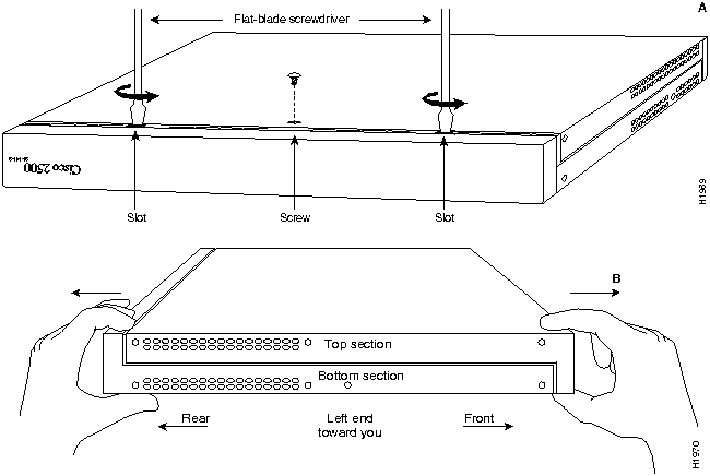
Open the router chassis to gain access to its interior components: the system card, system code SIMMs, and DRAM SIMMs. Following are the steps required to remove the chassis cover. When opening the chassis, use Parts A and B in Figure 1 as guides.

To remove the chassis cover, follow these steps.

Step 1 Turn OFF power, but to channel ESD voltages to ground, do not unplug the power cable.

Step 2 Remove all interface cables from the rear panel of the router.

Step 3 Turn the unit upside down so that the top of the chassis is resting on a surface, and the front of the chassis is toward you. (See Figure 1, Part A.)

h1970.gif

Figure 1 : Chassis Cover Removal---Part A (Top) and B (Bottom)

Step 4 Remove the single screw located on the bottom of the chassis (on the chassis side closest to you). Note that the chassis is comprised of two sections: top and bottom.

Step 5 If required, insert a medium flat-blade screwdriver into the slots shown in Figure 1,
Part A, and gently rotate the blade so that the top and bottom sections separate slightly.

Step 6 Holding the chassis with both hands, position it as shown in Figure 1, Part B.

Step 7 Gently pull the top section away from the bottom section. (See Figure 1, Part B.) The fit is very snug, so it may be necessary to work the chassis sections apart at one end and then the other, working back and forth.

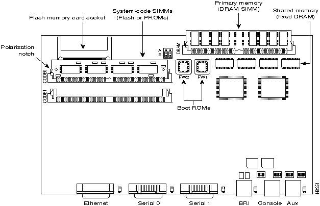
Step 8 When the top cover is off, set it aside. Figure 2 shows the layout of the system board, which is attached to the bottom section of the chassis.

fig_5.gif Warning Network hazardous voltages are accessible in the BRI cable. If you detach the BRI cable, detach the end away from the router first to avoid possible electric shock. Network hazardous voltages also are accessible on the system card in the area of the BRI port (RJ-45 connector), even when power is OFF (See Figure 2).

h2351.gif

Figure 2 : System Board Layout---Model 2503 Shown (Chassis, Fan, and Power Supply Not Shown)


Note To locate components in the following procedures, refer to Figure 2.

fig_6.gif Warning To prevent shock hazard and injury, do not touch the power supply and fan assemblies. These are not user-serviceable components.


Upgrading the Software

The upgrade software is on a Flash memory card. Insert the flash memory card is into the socket on the Cisco Model 2500 board and then turn the system ON to initiate the upgrade. The flash memory card is usable for one upgrade only.


Tools and Equipment Required

  • ESD-preventive wrist strap

  • The appropriate flash memory card for your software upgrade


Available Upgrades

A list of software upgrade options follows.

  • IP feature set only to the desktop feature set

  • Desktop feature set to the full feature set

  • IP feature set only to the full feature set

Your flash memory card is programmed for the feature set upgrade you purchased. If the wrong card is provided for your upgrade you will receive an error message such as:

THE UNIT HAS DESKTOP FEATURE SET
A DIFFERENT SOFTWARE PACKET IS NECESSARY TO UPGRADE FROM IP_ONLY TO FULL_FEATURE SET
If you receive a message similar to this, call your customer support representative.


Flash Card Upgrade

Following is the procedure for upgrading software using flash memory (PCMCIA) cards:

Step 1 Turn the power switch OFF, but to channel ESD voltages to ground, do not unplug the power cord.

Step 2 Attach an ESD-preventive wrist strap.

Step 3 Open the cover according to the procedure in the section "Opening the Chassis."

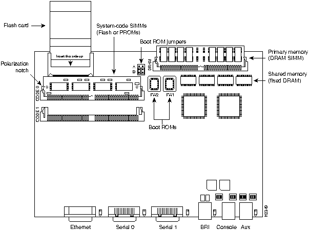
Step 4 Turn the chassis so the system board is in the position shown in Figure 4, with the primary memory DRAM SIMM socket away from you.

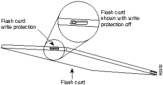
Step 5 Verify that the flash memory card is set with write protection off. The write protect switch is located on the top edge of the card when oriented with the printing right side up (see Figure 3).

h2352.gif

Figure 3 : Locating the Flash Card Write Protection Switch

Step 6 Locate the flash card socket at the left upper corner of the system board, and insert the card into the socket (see Figure 4).


h2349.gif

Figure 4 : Inserting the Flash Card


Note The example board layout in Figure 5-7 depicts a model 2501. The location of your PCMCIA flash card socket may differ slightly from that shown in the illustration depending on the model of your equipment.

Step 7 Reconnect the system console to the unit.

Step 8 Turn the power switch to the ON position. The system automatically starts the upgrade procedure. The upgrade screen will display on the system console (see Figure 5).

*****************************************************************************
THIS SOFTWARE CAN BE USED TO UPGRADE 2500 FROM IP_ONLY TO DESKTOP FEATURE SET
THIS UPGRADE CAN TAKE UPTO 3 MINUTES
*****************************************************************************

*****************************************************************************
DO YOU WANT TO UPGRADE YOUR 2500?
PLEASE ENTER 'Y' OR 'N': (Enter '?' for help)
*****************************************************************************

*****************************************************************************

PLEASE WAIT ....

UPGRADING SOFTWARE FEATURE SET FOR 2500 

THE UNIT WILL BE UPGRADED FROM IP_ONLY TO DESKTOP FEATURE SET

THIS CAN TAKE UP TO 3 MINUTES 

PLEASE DO NOT REMOVE THE CARD OR POWER CYCLE DURING THIS TIME 

*****************************************************************************

*****************************************************************************
THE UNIT HAS BEEN UPGRADED FROM IP_ONLY TO DESKTOP FEATURE SET
*****************************************************************************

*****************************************************************************
PLEASE TURN OFF THE UNIT AND REMOVE THE CARD
*****************************************************************************

Figure 5 : Example of Flash Card Upgrade Screen

Step 9 Enter "Y" when the upgrade screen displays the following message:


DO YOU WANT TO UPGRADE YOUR 2500?
PLEASE ENTER 'Y' OR 'N': (Enter '?' for help)

Step 10 When the update is complete the following message will display on the console screen:


PLEASE TURN OFF THE UNIT AND REMOVE THE CARD

Turn the power switch to OFF and then remove the flash card from the flash card socket.

Step 11 Remove your anti-static wrist strap and replace the router cover using the procedure in the section "Closing the Chassis."


Closing the Chassis

Following is the procedure for closing the chassis.


Tools Required

Following are the tools required for replacing the cover:

  • 1/4 inch (0.625 cm) flat-blade screwdriver

  • Size M 3.5 hex-head nut driver (optional)


Cover Replacement

After you perform the maintenance for your system, replace the cover by following these steps:

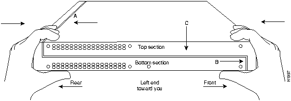
Step 1 Position the two chassis sections as shown in Figure 6.

Step 2 Referring to Figure 6, press the two chassis sections together and ensure the following:

  • The top section fits into the rear of the bottom section (See Part A in Figure 6).

  • The bottom section fits into the front of the top section (See Part B in Figure 6).

  • Each side of the top and bottom sections fits together (See Part C in Figure 6).

    fig_1.gif

Caution To fit the two sections together, it may be necessary to work them together at one end and then the other, working back and forth; however, use care to prevent bending the chassis edges.

h1997.gif

Figure 6 : Replacing the Chassis Cover

Step 3 When the two sections fit together snugly, turn the chassis so that the bottom is facing up, with the front panel toward you.

Step 4 Replace the cover screw. Tighten the screw to no more than 8 or 9 inch/pounds of torque.

Step 5 Reinstall the chassis on the wall, rack, desk, or table top.

Step 6 Replace all cables and turn ON the power to the chassis.

This concludes Upgrading Feature Sets with Flash Cards for Cisco 2500 Series Routers.

Cisco Information Online (CIO) is Cisco System's primary, real-time support channel. You can use your product serial number to activate CIO for a single user during your warranty period. maintenance customers and partners can self-register on CIO to obtain additional content and services.

Available 24 hours a day, 7 days a week, CIO provides a wealth of standard and value-added services to Cisco's customers and business partners. CIO services include product information, software updates, release notes, technical tips, the Bug Navigator, configuration notes, brochures, descriptions of service offerings, and download access to public an d authorized files.

CIO serves a wide variety of users through two interfaces that are updated and enhanced simultaneously---a character-based version and a multimedia version that resides on the World Wide Web (WWW). The character-based CIO (called "CIO Classic") supports Zmodem, Kermit, Xmodem, FTP, internet e-mail, and fax download options, and is excellent for quick access to information over lower bandwidths. The WWW version of CIO provides richly formatted documents with photographs, figures, graphics, and video, as well as hyperlinks to related information.

You can access CIO in the following ways:

  • WWW: http://www.cisco.com

  • Telnet: cio.cisco.com (198.92.32.130)

  • Modem: From North America, 408-526-8070; from Europe, 33 1 64 46 40 82. Use the following terminal settings: VT-100 emulation; data bits: 8; parity: none; stop bits: 1; and baud rates up to 14.4 kbps.

For a copy of CIO's Frequently Asked Questions (FAQ), contact cio-help@cisco.com. For additional information, contact cio-team@cisco.com.


Note If you are a network administrator and need personal technical assistance with a Cisco product that is under warranty or covered by a maintenance contract, contact Cisco's Technical Assistance Center (TAC) at 800 553-2447, 408 526-7209, or tac@cisco.com. To obtain general information about Cisco Systems, Cisco products, or upgrades, contact 800 553-6387, 408 526-7208, or cs-rep@cisco.com.

fig_3.gif

HomeTOCPrevNextGlossSearchHelp
-

Copyright 1988-1996 © Cisco Systems Inc.