|
|

The source-route bridging (SRB) algorithm was developed by IBM and proposed to the IEEE 802.5 committee as the means to bridge between all local-area networks (LANs). The IEEE 802.5 committee subsequently adopted SRB into the IEEE 802.5 Token Ring LAN specification.
Since its initial proposal, IBM has offered a new bridging standard to the IEEE 802 committee: the source-route transparent (SRT) bridging solution. See Chapter 31, "Mixed-Media Bridging," for more information on SRT bridging. SRT bridging eliminates pure SRBs entirely, proposing that the two types of LAN bridges be transparent bridges and SRT bridges. Although SRT bridging has achieved support, SRBs are still widely deployed.
SRBs are so named because they assume that the complete source-to-destination route is placed in all inter-LAN frames sent by the source. SRBs store and forward the frames as indicated by the route appearing in the appropriate frame field. Figure 30-1 illustrates a sample SRB network.
Figure 30-1 : Sample SRB Network
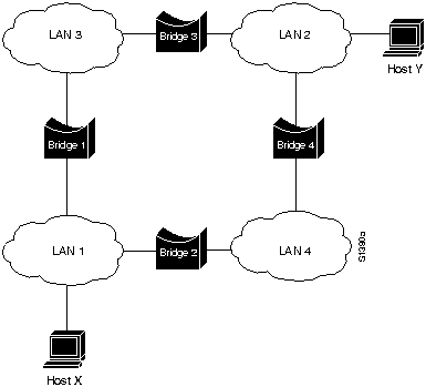
Referring to Figure 30-1, assume that Host X wishes to send a frame to Host Y. Initially, Host X does not know whether Host Y resides on the same or a different LAN. To determine this, Host X sends out a test frame. If that frame returns to Host X without a positive indication that Host Y has seen it, Host X must assume that Host Y is on a remote segment.
To determine the exact remote location of Host Y, Host X sends an explorer frame. Each bridge receiving the explorer frame (Bridges 1 and 2 in this example) copies the frame onto all outbound ports. Route information is added to the explorer frames as they travel through the internetwork. When Host X's explorer frames reach Host Y, Host Y replies to each individually using the accumulated route information. Upon receipt of all response frames, Host X chooses a path based on some predetermined criteria.
In the example in Figure 30-1, this process will yield two routes:
Host X must select one of these two routes. The IEEE 802.5 specification does not mandate the criteria Host X should use in choosing a route, but it does make several suggestions, including the following:
In most cases, the path contained in the first frame received will be used.
After a route is selected, it is inserted into frames destined for Host Y in the form of a routing information field (RIF). A RIF is included only in those frames destined for other LANs. The presence of routing information within the frame is indicated by the setting of the most significant bit within the source address field, called the routing information indicator (RII) bit.
The IEEE 802.5 RIF is structured as shown in Figure 30-2.
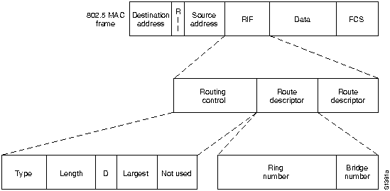
The fields of the RIF are as follows:
|
|
Copyright 1988-1996 © Cisco Systems Inc.