|
|
Transparent bridges were first developed at Digital Equipment Corporation (Digital) in the early 1980s. Digital submitted its work to the Institute of Electrical and Electronic Engineers (IEEE), which incorporated the work into the IEEE 802.1 standard. Transparent bridges are very popular in Ethernet/IEEE 802.3 networks
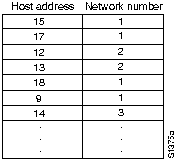
Transparent bridges are so named because their presence and operation are transparent to network hosts. When transparent bridges are powered on, they learn the network's topology by analyzing the source address of incoming frames from all attached networks. If, for example, a bridge sees a frame arrive on line 1 from Host A, the bridge concludes that Host A can be reached through the network connected to line 1. Through this process, transparent bridges build a table such as the one in
Figure 29-1.
Figure 29-1 : Transparent Bridging Table

The bridge uses its table as the basis for traffic forwarding. When a frame is received on one of the bridge's interfaces, the bridge looks up the frame's destination address in its internal table. If the table contains an association between the destination address and any of the bridge's ports aside from the one on which the frame was received, the frame is forwarded out the indicated port. If no association is found, the frame is flooded to all ports except the inbound port. Broadcasts and multicasts are also flooded in this way.
Transparent bridges successfully isolate intrasegment traffic, thereby reducing the traffic seen on each individual segment. This usually improves network response times as seen by the user. The extent to which traffic is reduced and response times are improved depends on the volume of intersegment traffic relative to the total traffic as well as the volume of broadcast and multicast traffic.
Without a bridge-to-bridge protocol, the transparent bridge algorithm fails when there are multiple paths of bridges and local-area networks (LANs) between any two LANs in the internetwork.
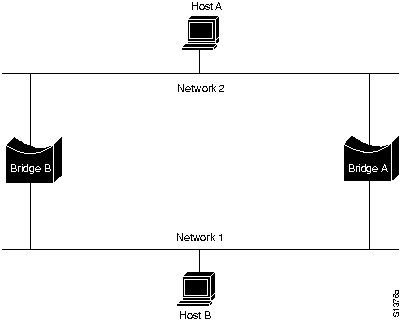
Figure 29-2 illustrates such a bridging loop.
Figure 29-2 : Inaccurate Forwarding and Learning in Transparent Bridging Environments

Suppose Host A sends a frame to Host B. Both bridges receive the frame and correctly conclude that Host A is on Network 2. Unfortunately, after Host B receives two copies of Host A's frame, both bridges will again receive the frame on their network 1 interfaces because all hosts receive all messages on broadcast LANs. In some cases, the bridges will then change their internal tables to indicate that Host A is on network 1. If so, when Host B replies to Host A's frame, both bridges will receive and subsequently drop the replies because their tables will indicate that the destination (Host A) is on the same network segment as the frame's source.
In addition to basic connectivity problems such as the one just described, the proliferation of broadcast messages in networks with loops represents a potentially serious network problem. Referring again to Figure 29-2, assume that Host A's initial frame is a broadcast. Both bridges will forward the frames endlessly, using all available network bandwidth and blocking the transmission of other packets on both segments.
A topology with loops such as that shown in Figure 29-2 can be useful as well as potentially harmful. A loop implies the existence of multiple paths through the internetwork. A network with multiple paths from source to destination can increase overall network fault tolerance through improved topological flexibility.
The spanning-tree algorithm (STA) was developed by Digital Equipment Corporation, a key Ethernet vendor, to preserve the benefits of loops while eliminating their problems. Digital's algorithm was subsequently revised by the IEEE 802 committee and published in the IEEE 802.1d specification The Digital algorithm and the IEEE 802.1d algorithm are not the same, nor are they compatible.
The STA designates a loop-free subset of the network's topology by placing those bridge ports that, if active, would create loops into a standby (blocking) condition. Blocking bridge ports can be activated in the event of primary link failure, providing a new path through the internetwork.
The STA uses a conclusion from graph theory as a basis for constructing a loop-free subset of the network's topology. Graph theory states the following:
For any connected graph consisting of nodes and edges connecting pairs of nodes, there is a spanning tree of edges that maintains the connectivity of the graph but contains no loops.
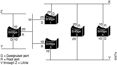
Figure 29-3 illustrates how the STA eliminates loops. The STA calls for each bridge to be assigned a unique identifier. Typically, this identifier is one of the bridge's Media Access Control (MAC) addresses plus a priority. Each port in every bridge is also assigned a unique (within that bridge) identifier (typically, its own MAC address). Finally, each bridge port is associated with a path cost. The path cost represents the cost of transmitting a frame onto a LAN through that port. In
Figure 29-3, path costs are noted on the lines emanating from each bridge. Path costs are usually defaulted, but can be assigned manually by network administrators.
Figure 29-3 : Transparent Bridge Network before Running STA

The first activity in spanning-tree computation is the selection of the root bridge, which is the bridge with the lowest value bridge identifier. In Figure 29-3, the root bridge is Bridge 1. Next, the root port on all other bridges is determined. A bridge's root port is the port through which the root bridge can be reached with the least aggregate path cost. This value (the least aggregate path cost to the root) is called the root path cost.
Finally, designated bridges and their designated ports are determined. A designated bridge is the bridge on each LAN that provides the minimum root path cost. A LAN's designated bridge is the only bridge allowed to forward frames to and from the LAN for which it is the designated bridge. A LAN's designated port is the port that connects it to the designated bridge.
In some cases, two or more bridges can have the same root path cost. For example, in Figure 29-3, Bridges 4 and 5 can both reach Bridge 1 (the root bridge) with a path cost of 10. In this case, the bridge identifiers are used again, this time to determine the designated bridges. Bridge 4's LAN V port is selected over Bridge 5's LAN V port.
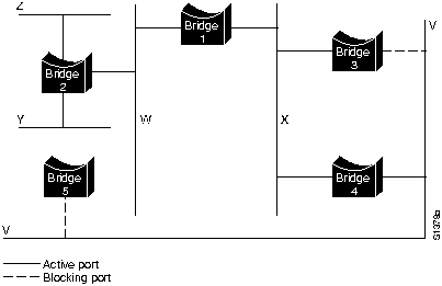
Using this process, all but one of the bridges directly connected to each LAN are eliminated, thereby removing all two-LAN loops. The STA also eliminates loops involving more than two LANs, while still preserving connectivity. Figure 29-4 shows the results of applying the STA to the network shown in Figure 29-3. Figure 29-4 shows the tree topology more clearly. Comparing this figure to the pre-spanning-tree figure shows that the STA has placed both Bridge 3's and Bridge 5's ports to LAN V in standby mode.
Figure 29-4 : Transparent Bridge Network After Running STA

The spanning-tree calculation occurs when the bridge is powered up and whenever a topology change is detected. The calculation requires communication between the spanning-tree bridges, which is accomplished through configuration messages (sometimes called bridge protocol data units, or BPDUs). Configuration messages contain information identifying the bridge that is presumed to be the root (root identifier) and the distance from the sending bridge to the root bridge (root path cost). Configuration messages also contain the bridge and port identifier of the sending bridge and the age of information contained in the configuration message.
Bridges exchange configuration messages at regular intervals (typically one to four seconds). If a bridge fails (causing a topology change), neighboring bridges will soon detect the lack of configuration messages and initiate a spanning-tree recalculation.
All transparent bridge topology decisions are made locally. Configuration messages are exchanged between neighboring bridges. There is no central authority on network topology or administration.
Transparent bridges exchange configuration messages and topology change messages. Configuration messages are sent between bridges to establish a network topology. Topology change messages are sent after a topology change has been detected to indicate that the STA should be rerun.
The IEEE 802.1d configuration message format is shown in Figure 29-5.
Figure 29-5 : Transparent Bridge Configuration Message Format

The fields of the transparent bridge configuration message are as follows:
Topological change messages consist of only 4 bytes. They include a protocol identifier field, which contains the value zero; a version field, which contains the value zero; and a message type field, which contains the value 128.
|
|
Copyright 1988-1996 © Cisco Systems Inc.