|
|
Increasing communication speeds are an undeniable networking trend. Local-area networks (LANs) have recently moved into the 100-Mbps range with Fiber Distributed Data Interface (FDDI). Local applications driving these speed increases include imaging, video, and today's distributed (client-server) data transmission applications. Faster computer platforms will continue to drive up rates in the local environment as they make new, high-speed applications possible.
Higher-throughput wide-area network (WAN) pipes have been developed to match the ever-increasing LAN speeds and to allow mainframe channel extension over WANs. WAN technologies such as Frame Relay, Switched Multimegabit Data Service (SMDS), Synchronous Optical Network (SONET), and Broadband Integrated Services Digital Network (Broadband ISDN, or simply BISDN) take advantage of new digital and fiber-optic technologies to ensure that WANs are not a significant bottleneck in end-to-end communication over large geographic areas. See Chapter 13, "Frame Relay," and Chapter 14, "Switched Multimegabit Data Service," for more information on Frame Relay and SMDS, respectively.
With higher speeds being achieved in both the local and the wide-area environments, a data terminal equipment (DTE)/data circuit-terminating equipment (DCE) interface that could bridge these two worlds without becoming a bottleneck became a critical need. Classical DTE/DCE interface standards such as EIA/TIA-232 and V.35 are not capable of supporting T3, a digital WAN service that operates at 45 Mbps, or similar rates. By the late 1980s, it was clear that a new DTE/DCE protocol was needed.
The High-Speed Serial Interface (HSSI) is a DTE/DCE interface developed by Cisco Systems and T3plus Networking to address the need for high-speed communication over WAN links. The HSSI specification is available to any organization wishing to implement HSSI. So far, over 150 copies of the specification have been distributed, and dozens of companies have implemented or are currently implementing an HSSI solution. In less than 3 years, HSSI has become a de facto industry standard.
HSSI is now in the American National Standards Institute (ANSI) Electronic Industries Association (EIA)/TIA TR30.2 committee for formal standardization. It has recently moved into the International Telecommunication Union Telecommunication Standardization Sector (ITU-T) (formerly the Consultative Committee for International Telegraph and Telephone [CCITT]) and the International Organization for Standardization (ISO), and is expected to be standardized by these bodies.
HSSI defines both the electrical and the physical DTE/DCE interface. It therefore corresponds to the physical layer of the OSI reference model. HSSI technical characteristics are summarized in Table 8-1.
Table 8-1 : HSSI Technical Characteristics
| Characteristic | Value |
|---|---|
| Maximum signaling rate | 52 Mbps |
| Maximum cable length | 50 feet |
| Number of connector pins | 50 |
| Interface | DTE-DCE |
| Electrical technology | Differential ECL |
| Typical power consumption | 610 mW |
| Topology | Point-to-point |
| Cable type | Shielded twisted-pair wire |
The maximum signaling rate of HSSI is 52 Mbps. At this rate, HSSI can handle the T3 speeds (45 Mbps) of many of today's fast WAN technologies, the Office Channel -1 (OC-1) speeds (52 Mbps) of the synchronous digital hierarchy (SDH), and can easily provide high-speed connectivity between LANs such as Token Ring and Ethernet.
The use of differential emitter-coupled logic (ECL) helps HSSI achieve high data rates and low noise levels. ECL has been used in Cray interfaces for years and is also specified by the ANSI High-Performance Parallel Interface (HIPPI) communications standard for supercomputer LAN communications. ECL is off-the-shelf technology that permits excellent retiming on the receiver, resulting in reliable timing margins.
The flexibility of the HSSI clock and data signaling protocol makes user (or vendor) bandwidth allocation possible. The DCE controls the clock by changing its speed or by deleting clock pulses. In this way, the DCE can allocate bandwidth between applications. For example, a PBX may require a particular amount of bandwidth, a router another amount, and a channel extender a third amount. Bandwidth allocation is key to making T3 and other broadband services affordable and popular.
HSSI uses a subminiature, FCC-approved 50-pin connector that is smaller than its V.35 counterpart. To reduce the need for male-male and female-female adapters, HSSI cable connectors are specified as male. The HSSI cable uses the same number of pins and wires as the Small Computer Systems Interface 2 (SCSI-2) cable, but the HSSI electrical specification is tighter.
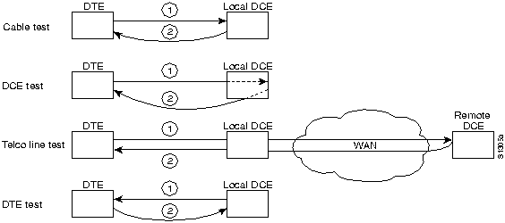
For a high level of diagnostic input, HSSI provides four loopback tests. These tests are shown in Figure 8-1. The first provides a local cable test as the signal loops back after it reaches the DTE port. The second test reaches the line port of the local DCE. The third test reaches the line port of the remote DCE. Finally, the fourth test is a DCE-initiated test of the DTE's DCE port.
Figure 8-1 : Four HSSI Loopback Tests

HSSI assumes a peer-to-peer intelligence in the DCE and DTE. The control protocol is simplified, with just two control signals required ("DTE available" and "DCE available"). Both signals must be asserted before the data circuit is valid. The DCE and DTE are expected to be able to manage the networks behind their interfaces. Reducing the number of control signals improves circuit reliability by reducing the number of circuits that can fail.
|
|
Copyright 1988-1996 © Cisco Systems Inc.