|
|

Switched Multimegabit Data Service
Switched Multimegabit Data Service (SMDS) is a packet-switched datagram service designed for very high-speed wide-area data communications. SMDS offers data throughputs that will initially be in the 1- to 34-Mbps range and is being deployed in public networks by the carriers in response to two trends. The first trend is the proliferation of distributed processing and other applications that require high-performance networking. The second trend is the decreasing cost and high-bandwidth potential of fiber media, making support of such applications over a wide-area network (WAN) viable.
SMDS is described in a series of specifications produced by Bell Communications Research (Bellcore) and adopted by the telecommunications equipment providers and carriers. One of these specifications describes the SMDS Interface Protocol (SIP), which is the protocol between a user device (referred to as customer premises equipment, or CPE), and SMDS network equipment.
The SIP is based on an IEEE standard protocol for metropolitan-area networks (MANs): that is, the IEEE 802.6 Distributed Queue Dual Bus (DQDB) standard. Using this protocol, CPE such as routers can be attached to an SMDS network and use SMDS service for high-speed internetworking.
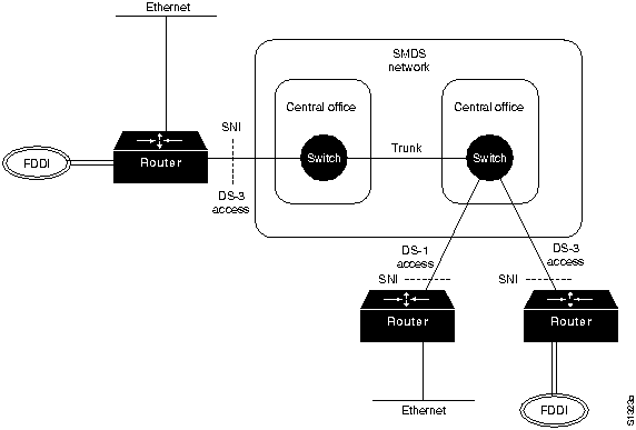
Figure 14-1 shows an internetworking scenario using SMDS. In this figure, access to SMDS is provided over either a 1.544-Mbps (DS-1, or Digital Signal 1) or 44.736-Mbps (DS-3, or Digital Signal 3) transmission facility. Although SMDS is usually described as a fiber-based service, DS-1 access can be provided over either fiber or copper-based media with sufficiently good error characteristics. The demarcation point between the carrier's SMDS network and the customer's equipment is referred to as the subscriber network interface (SNI).
Figure 14-1 : SMDS Internetworking Scenario
SMDS data units are capable of containing up to 9,188 octets (bytes) of user information. SMDS is therefore capable of encapsulating entire IEEE 802.3, IEEE 802.4, IEEE 802.5, and FDDI frames. The large packet size is consistent with the high-performance objectives of the service.
Like other datagram protocols, SMDS data units carry both a source and a destination address. The recipient of a data unit can use the source address to return data to the sender and for functions such as address resolution (discovering the mapping between higher-layer addresses and SMDS addresses). SMDS addresses are 10-digit addresses that resemble conventional telephone numbers.
In addition, SMDS supports group addresses that allow a single data unit to be sent and then delivered by the network to multiple recipients. Group addressing is analogous to multicasting on local-area networks (LANs) and is a valuable feature in internetworking applications where it is widely used for routing, address resolution, and dynamic discovery of network resources (such as file servers).
SMDS offers several other addressing features. Source addresses are validated by the network to ensure that the address in question is legitimately assigned to the SNI from which it originated. Thus, users are protected against address spoofing---that is, a sender pretending to be another user. Source and destination address screening is also possible. Source address screening acts on addresses as data units are leaving the network, while destination address screening acts on addresses as data units are entering the network. If the address is disallowed, the data unit is not delivered. With address screening, a subscriber can establish a private virtual network that excludes unwanted traffic. This provides the subscriber with an initial security screen and promotes efficiency because devices attached to SMDS do not have to waste resources handling unwanted traffic.
To accommodate a range of traffic requirements and equipment capabilities, SMDS supports a variety of access classes. Different access classes determine the various maximum sustained information transfer rates as well as the degree of burstiness allowed when sending packets into the SMDS network.
On DS-3-rate interfaces, access classes are implemented through credit management algorithms, which track credit balances for each customer interface. Credit is allocated on a periodic basis, up to some maximum. Then, the credit balance is decremented as packets are sent to the network.
The operation of the credit management scheme essentially constrains the customer's equipment to some sustained or average rate of data transfer. This average rate of transfer is less than the full information carrying bandwidth of the DS-3 access facility. Five access classes, corresponding to sustained information rates of 4, 10, 16, 25, and 34 Mbps, are supported for DS-3 access interface. The credit management scheme is not applied to DS1rate access interfaces.
Access to the SMDS network is accomplished via SIP. The SIP is based on the DQDB protocol specified by the IEEE 802.6 MAN standard. The DQDB protocol defines a Media Access Control (MAC) protocol that allows many systems to interconnect via two unidirectional logical buses.
As designed by IEEE 802.6, the DQDB standard can be used to construct private, fiber-based MANs supporting a variety of applications including data, voice, and video. This protocol was chosen as the basis for SIP because it was an open standard, could support all the SMDS service features, was designed for compatibility with carrier transmission standards, and is aligned with emerging standards for Broadband ISDN (BISDN). As BISDN technology matures and is deployed, the carriers intend to support not only SMDS but broadband video and voice services as well.
To interface to SMDS networks, only the connectionless data portion of the IEEE 802.6 protocol is needed. Therefore, SIP does not define voice or video application support.
When used to gain access to an SMDS network, operation of the DQDB protocol across the SNI results in an access DQDB. The term access DQDB distinguishes operation of DQDB across the SNI from operation of DQDB in any other environment (such as inside the SMDS network). A switch in the SMDS network operates as one station on an access DQDB, while customer equipment operates as one or more stations on the access DQDB.
Because the DQDB protocol was designed to support a variety of data and nondata applications and because it is a shared medium access control protocol, it is relatively complex. It has two parts:
There are two ways to configure CPE on the SMDS access DQDB, as shown in Figure 14-2. In a single-CPE configuration, the access DQDB simply connects the switch in the carrier network and one subscriber-owned station (CPE). In a multi-CPE configuration, the access DQDB consists of the switch in the network and multiple interconnected CPE at the subscriber site. In this latter configuration, all CPEs must belong to the same subscriber.
Figure 14-2 : Single-CPE and Multi-CPE Configurations
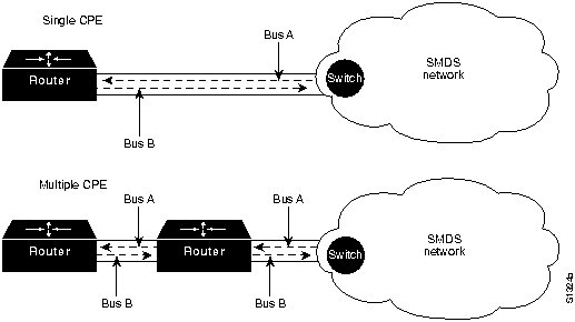
In the single-CPE case, the access DQDB is essentially just a two-node DQDB subnetwork. Each of the nodes (the switch and the CPE) transfer data to the other via a unidirectional logical bus. There is no contention for this bus because there are no other stations. Because of this, the distributed queueing algorithm need not be used. Without the complexity of the distributed queuing algorithm, SIP for single-CPE configurations is much simpler than SIP for multi-CPE configurations.
The SIP can be logically partitioned into three levels, as shown in Figure 14-3.
Figure 14-3 : Encapsulation of User Information by SIP Levels
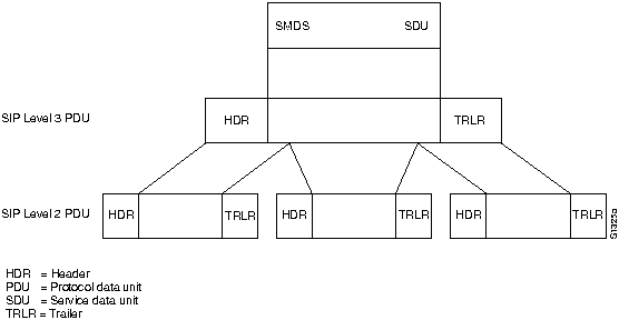
SIP Level 3 operation involves the encapsulation of SMDS service data units (SDUs) in a Level 3 header and trailer. Level 3 protocol data units (PDUs) are then broken into Level 2 PDUs as appropriate to conform to Level 2 specifications.
The SIP Level 3 PDU is reasonably complex. It is shown in Figure 14-4.
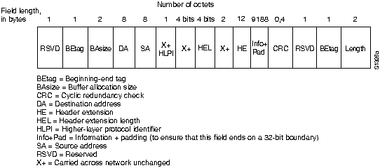
Fields marked X+ in the figure are not used in the provision of SMDS, but are present in the protocol to ensure alignment of the SIP format with the DQDB protocol format. Values placed in these fields by the CPE must be delivered unchanged by the network.
The two reserved fields must be populated with zeros. The two BEtag fields contain an identical value and are used to form an association between the first and last segments or Level 2 PDUs of a SIP Level 3 PDU. These fields can be used to detect the condition where the last segment of one Level 3 PDU and the first segment of the next Level 3 PDU are both lost, resulting in receipt of an invalid Level 3 PDU.
The BAsize field contains the buffer allocation size.
The destination and source addresses consist of two parts: an address type and an address. In both cases, the address type occupies the four most significant bits of the field. If the address is a destination address, the address type may be either "1100" or "1110." The former indicates a 60-bit individual address; the latter indicates a 60-bit group address. If the address is a source address, the address type field can only indicate an individual address.
Bellcore Technical Advisories specify how addresses consistent in format with the North American Numbering Plan (NANP) are to be encoded in the source and destination address fields. In this case, the four most significant bits of each of the source and destination address subfields contain the value "0001," which is the internationally defined country code for North America. The next 40 bits contain the binary coded decimal (BCD)-encoded values of the 10-digit SMDS, NANP-aligned addresses. The final 16 (least-significant) bits are populated with ones for padding.
The higher-layer protocol identifier field indicates what type of protocol is encapsulated in the information field. This value is important to systems using the SMDS network (such as Cisco routers) but is not processed or changed by the SMDS network.
The header extension length (HEL) field indicates the number of 32-bit words in the header extension field. Currently, the size of this field for SMDS is fixed at 12 bytes. Therefore, the HEL value is always "0011."
The header extension (HE) field is currently identified as having two uses. One is to contain an SMDS version number, which is used to determine what version of the protocol is being used. The other use is to convey a carrier selection value providing the ability to select a particular interexchange carrier to carry SMDS traffic from one local carrier network to another. In the future, other information may be defined to be conveyed in the header extension field, if required.
The CRC field contains a cyclic redundancy check value.
Level 3 PDUs are segmented into uniformly sized (53-octet) Level 2 PDUs, often referred to as slots or cells. The format of the SIP Level 2 PDU is shown in Figure 14-5.
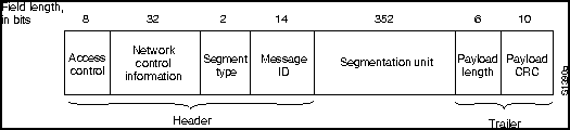
The access control field of the SIP Level 2 PDU contains different values depending on the direction of information flow. If the slot is sent from the switch to the CPE, only the indication of whether the PDU contains information or not is important. If the slot was sent from the CPE to the switch, and if the configuration is multi-CPE, this field can also carry request bits that indicate bids for slots on the bus going from the switch to the CPE. Further detail on how these request bits are used to implement distributed queuing media access control can be obtained from the IEEE 802.6 standard.
The network control information field can contain only two possible values. One particular bit pattern is included when the PDU contains information; another is used when it does not.
The segment type field indicates whether this Level 2 PDU is the beginning slot, the last slot, or a slot from the middle of a Level 3 PDU. Segment type values are shown in Table 14-1.
Table 14-1 : Segment Type Values
| Value | Meaning |
|---|---|
| 00 | Continuation of message |
| 01 | End of message |
| 10 | Beginning of message |
| 11 | Single segment message |
The message ID field allows association of Level 2 PDUs with a Level 3 PDU. The message ID is the same for all segments of a given Level 3 PDU. On a multi-CPE access DQDB, Level 3 PDUs originating from different CPE must have different message IDs. This allows the SMDS network receiving interleaved slots from different Level 3 PDUs to associate each Level 2 PDU with the correct Level 3 PDU. Successive Level 3 PDUs from the same CPE may have identical message IDs. This presents no ambiguity, because any single CPE must send all Level 2 PDUs from one Level 3 PDU before it begins sending Level 2 PDUs of a different Level 3 PDU.
The segmentation unit field is the data portion of the PDU. In the event of an empty Level 2 PDU, this field is populated with zeros.
The payload length field indicates how many bytes of a Level 3 PDU are actually contained in the segmentation unit field. If the Level 2 PDU is empty, this field is also populated with zeros.
Finally, the payload CRC field contains a 10-bit cyclic redundancy check (CRC) value used to detect errors over the segment type, message ID, segmentation unit, payload length, and payload CRC fields. This CRC does not cover the access-control or network-control information fields.
SIP Level 1 provides the physical link protocol, which operates at DS-3 or DS-1 rates between the CPE and the network. SIP Level 1 is divided into two parts: the transmission system sublayer and the Physical Layer Convergence Protocol (PLCP). The transmission system sublayer defines the characteristics and method of attachment to the transmission link, that is, the DS-3 or DS1. The PLCP specifies how the Level 2 PDUs, or slots, are to be arranged relative to the DS-3 or DS-1 frame, and defines certain management information.
Because the SIP is based on IEEE 802.6, it has the advantage of compatibility with future BISDN interfaces that will support not only data but video and voice applications as well. However, this compatibility does cost some protocol overhead, which must be taken into account when calculating overall data throughput that can be achieved using SIP. Over a DS3 access DQDB, the total bandwidth available for Level 3 PDU user data is approximately 34 Mbps. Over a DS-1 access, approximately 1.2 Mbps can carry user data.
The use of the IEEE 802.6 MAN MAC protocol as the basis for the SMDS SIP means that local communication between CPE on the same access DQDB is possible. Some of this local communication will be visible to the switch serving the SNI and some will not. The switch therefore must use the destination address of a data unit to differentiate between data units intended for SMDS-based transfer and data units intended for local transmission among multiple CPE sharing an access DQDB.
Inside the carrier network, the high-speed packet-switching capability required by SMDS can be provided by a number of different technologies. In the near term, switches based on MAN technology such as the DQDB standard are being included in a number of networks. A series of Technical Advisories produced by Bellcore specify standard requirements on network equipment for such functions as the following:
As has been noted, the IEEE 802.6 protocol and SIP were intentionally designed to align with the principal BISDN protocol referred to as Asynchronous Transfer Mode (ATM). ATM and IEEE 802.6 belong to a class of protocols often referred to as fast packet-switching or cell relay protocols. These protocols organize information into small, fixed-size cells (Level 2 PDUs in SIP terminology). Fixed-size cells can be processed and switched in hardware at very high speeds. This tightly constrains delay characteristics, making cell relay protocols useful for video and voice applications. As ATM-based switching equipment becomes available, this technology will also be introduced into networks providing SMDS.
|
|
Copyright 1988-1996 © Cisco Systems Inc.