|
|
After you install VlanDirector, you are ready to work with the application and become familiar with its features.
This section provides information on how to navigate in VlanDirector, use the VlanDirector features, and perform initial VLAN configuration tasks.
The following is a list of the steps required to become familiar with the VlanDirector application and features. The procedure for completing each task follows this summary.
You can start VlanDirector from SunNet Manager, HP OpenView, or from the UNIX command line.
To start VlanDirector from the SunNet Manager Tools menu, follow these steps:
source <install directory>/etc/install.cshrc
snm -i
To start VlanDirector from HP OpenView, do the following:
To start VlanDirector from a device icon, perform the following steps:
To start VlanDirector from the UNIX command line, perform the following steps:
vdirector
<vlvroot>/bin/vdirector
This section provides information on command options and arguments that can be used with the vdirector command.
The following is the full syntax of the vdirector command:
vdirector [-db <config or known network DB>] [-cdp <seed discovery device>] [-v <version>] [-help] [-csf <community file>]
All of the arguments shown above are optional. The vdirector command options are described in the following table:
| Option | Meaning |
|---|---|
| -csf | Specifies a community string file name |
| -db | Specifies the name of the known network or configuration. If there is both a known network and a configuration with the same name, VlanDirector uses the known network. |
| -cdp | Specifies the IP address or host name of a device to use as the seed CDP discovery device if necessary. |
| -v | Displays the version of the software and then exits. |
| -help | Displays the format and syntax of the vdirector command. |
The vdirector command uses start-up options in the following order of priority:
For example, if you specified a seed switch using the VLV_SEED_SWITCH environment variable, you could start VlanDirector using a different seed switch by using the -cdp command line option. Under these circumstances, VlanDirector would start using the command line option.
The VlanDirector application is primarily documented with online help.
After you launch the VlanDirector application, use the help system to get information about using the VlanDirector interface, navigating within the product, and finding information on a specific topic.
Help is available in the following ways:
| For this information | Do this |
|---|---|
| How to use the help system | On the Names window, select Help>Using Help. |
| Self-contained help system describing how to use the product features | On the Names window, select Help>Using VlanDirector. |
| Version information | On the Names window, select Help>About VlanDirector. |
| Context-sensitive help on any VlanDirector windows | Click the Help button in the window or search within the Help system. |
When you start VlanDirector, it automatically performs a discovery of your network. If you are getting started with the product, you do not need to perform any of the discovery tasks listed here now, but you may want to refer to this information later or to help you become familiar with the discovery process.
VlanDirector finds out or discovers the devices in the network using Cisco Discovery Protocol (CDP). VlanDirector can only discover devices that support CDP. The discovered devices and links between them form a known network. The known network can consist of up to 100 devices. The discovery process stops when it reaches the 100th device. You can include and exclude devices in the known network so that it includes only devices that you want included in the known network. You can also save a known network.
Instructions for performing the following discovery tasks are provided later in this chapter:
To discover a device, VlanDirector must have the following information:
After you launch VlanDirector, VlanDirector displays the following windows by default:
When the discovery process is completed, these windows are populated with discovered information.
From VlanDirector, you can also display the following windows:
All of these windows, except the Names window, display various views of your network and are explained in detail later in this chapter.
The Names window displays the names of existing VLANs and folders. Use this window to create the name of a new VLAN or to organize groups of VLANs into folders, in the same way that you would organize files into folders or directories.
The Names window also provides menu commands to manage configurations and known networks. From the Names window, you can display other VLAN views. Figure 3-1 shows the Names window.
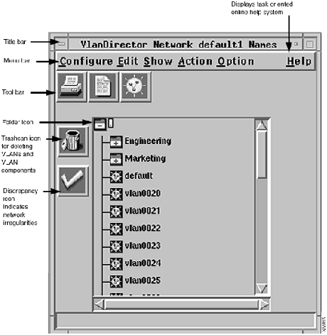
The Names window has the following characteristics:
Menu Bar
The menu bar contains the commands that enable you to work with VLAN configurations, create VLAN names, and control many operating characteristics of the application, such as which network views are displayed.
Tool Bar
Icons in the toolbar include a printer symbol, which prints the Names window; the paper symbol, which opens a Trunk Details Report window; and the Sun symbol, which opens a create dialog box for creating a VLAN name or folder.
Icon Bar -- Left Side of Pane
There are also icons appearing down the left side of the Names window. They include the trashcan, the background activity icon, and the discrepancies icon. The background activity icon looks like a magnifying glass. When open, VlanDirector is performing a discovery of network devices or installing VLANs in a known network. If you click this icon while the discovery or installation is in process, VlanDirector stops the discovery or installation.
Central Scrollable Pane -- Names List
VLANs and folder names appear in the central scrollable pane.
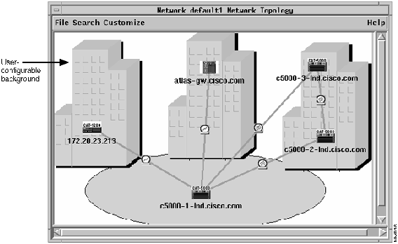
The Network Topology window shows all the physical devices and the links between them in the configuration or in the known network, depending on which is loaded. It displays up to 100 devices.
You can customize the appearance and amount of information this window displays. You can change its background, add or remove decorations such as building symbols, and then save and reload these changes.
You can also add links to a VLAN from the Network Topology window. Figure 3-2 shows an example of the Network Topology window.
From this window you can:
Figure 3-2 Network Topology Window
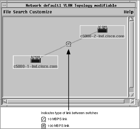
The VLAN Topology window shows all the devices and the links between them in the currently selected VLANs. It displays up to 100 devices.
From this window you can:
You can customize the appearance and the amount of information this window displays by changing its background, or adding or removing decorations such as building symbols. Figure 3-3 shows an example of the VLAN Topology window.
Figure 3-3 VLAN Topology Window
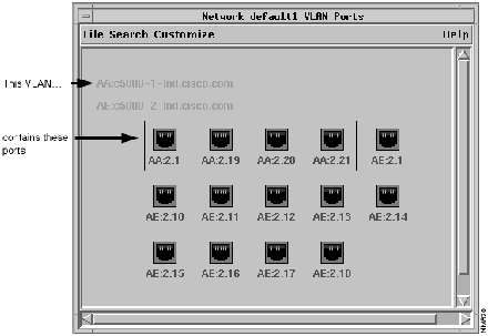
The VLAN Ports window displays the ports in the VLAN(s) that you selected in the Names window and displays a legend to identify the switch the ports are on. The names of the switches that include VLAN ports are listed on the top left portion of the window. To determine what switch a port belongs to, match the letters listed at the beginning of the label underneath the port with the corresponding letters in the list of switch names.
For example, if the port label begins with the letters AB, locate the switch beginning with the letters AB to find the switch on which the port is located. Figure 3-4 shows an example of the VLAN Ports window and illustrates how to identify which ports belong to a VLAN.
From this window you can:
The VLAN Devices window shows all the devices assigned to the selected VLAN. You can click the right or MENU mouse button on a device icon to view additional information about the device. The VLAN Devices window does not show links between the devices.
Figure 3-5 VLAN Devices window
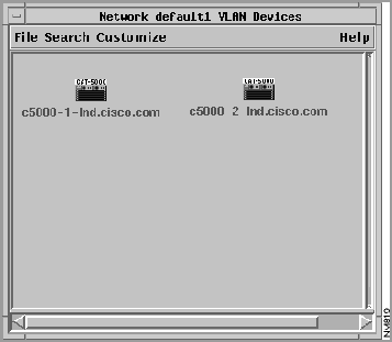
From this window you can
The Legends window shows you the name and corresponding color for each selected VLAN. When you first launch VlanDirector, this window displays the following legend:
Names of ports and devices in a selected VLAN are displayed in the VLAN Devices, Topology, or Ports window in the appropriate color from the legend.
VlanDirector combines the following navigational aids to help you to become familiar with the user interface and perform VLAN configuration. If you are getting started with VlanDirector, familiarize yourself with these navigational aids before you perform VLAN configuration tasks.
VlanDirector enables you to drag and drop symbolic representations of network components, following Motif standards. To drag and drop an item on a target, select the icon representing that item and then drag it to the target. You can drag or drop a single item, or more than one item simultaneously. For example, when creating a new VLAN, you can drag and drop a port from a CiscoView display to the VLAN Ports window to add a port to a VLAN. Figure 3-6 shows an example of dragging a group of ports from a CiscoView window to a VlanDirector Ports window.
Figure 3-6 Example of Drag-and-Drop from CiscoView to VlanDirector
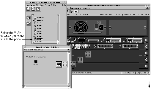
In this example, multiple ports are dragged from the CiscoView display to the VLAN ports window. Multiple ports are represented by a single port icon.
To drag and drop an item, for example, a port:
You can drag and drop multiple items of the same type. To drag and drop more than one item, for example, multiple ports:
When you are dragging an object or icon, you can determine where you are permitted to drop it by the color of the icon. When dragging over a valid target, the object (for example, a port icon) displays a black and white frame. Dropping an object over a valid target causes the object to disappear indicating that the desired action has been taken. Dropping an object over an invalid target also causes the object to disappear, indicating no action is taken. When dragging over an invalid target, the object has a black and light beige frame. No error message is displayed.
A valid drop target cannot always accept a dropped icon or object. When this occurs, an error message is displayed. For example, the VLAN Devices, Ports, or Topology window can accept a port from CiscoView if it is displaying only one VLAN. If it is displaying more than one VLAN, it cannot accept the port from CiscoView.
When dragging an item to the trashcan, make sure that you drop the arrowhead of the pointer attached to the left corner of the dragged icon in the trashcan, as shown in Figure 3-7.
Figure 3-7 Dragging and Dropping to the Trashcan
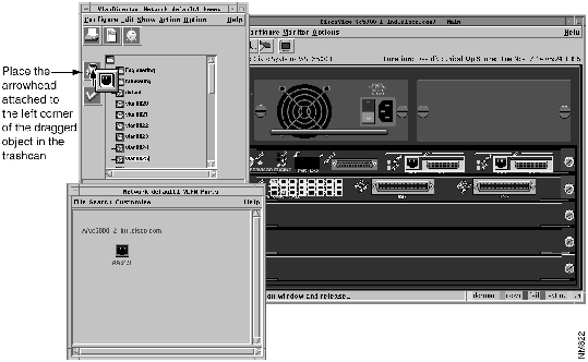
CiscoView is a device management application that enables you to display a graphical representation of each network device, display configuration and performance information, and perform minor troubleshooting tasks.
CiscoView is provided with VlanDirector. Use CiscoView with VlanDirector to add or delete ports to and from a VLAN by dragging and dropping ports from a CiscoView display into a VlanDirector display, as shown in Figure 3-7.
To start CiscoView
or
VlanDirector uses color to indicate port status, VLAN membership, and icon selection.
CiscoView and VlanDirector use the following color-coded scheme to indicate port status.
Magenta -- Testing
Green -- Up
Brown -- Down
Cyan -- Dormant
Red -- Failure
Orange -- Minor Alarm
To display the color-coded legend for VLAN membership, in the Names window select Option>Show Legend.
The VLAN membership legend shows the correspondence between selected VLANs in the Names window and colors in the VLAN Topology, Devices, and Ports windows, and port highlights in CiscoView.
When you select a VLAN in the Names window, it is assigned a color. VlanDirector displays the names of ports and devices belonging to this VLAN in this color and CiscoView outlines the ports in the same color.
If a port or device belongs to more than one VLAN, it is identified in the legend with the label ":multiple" and its assigned color, which by default is light brown.
VlanDirector uses color to indicate when an icon is selected or active, and when certain operations are valid. Items, such as folder names, appear yellow when selected. Ports and devices are outlined in yellow when selected.
Similarly, when dragging an icon from one window to another, VlanDirector uses color to indicate where you can drop the icon. For example, when dragging a port icon from CiscoView, VlanDirector indicates which window can accept that port by changing the inside border of the icon from beige to white.
Colors are configurable. You can set both the colors and the number of colors in the palette by editing the.cvlanrc file. If the number of colors in the palette is fewer than the number of VLANs you created, the colors are reused, causing them to lose significance. This occurs, for example, if you specified the following colors:
red, orange, yellow, green, blue
and you selected the following VLANs:
VLAN 1 Red
VLAN 22 Orange
VLAN 3 Yellow
VLAN 14 Green
VLAN 5 Blue
VLAN 26 Red
VLAN 7 Orange
The colors are reused and red and orange are assigned to more than one VLAN.
To resolve this problem, edit the ~/.cvlanrc file to include additional colors from the rgb.txt file on your system. If you are using Open Windows, the rgb.txt file is located in $OPENWINHOME/lib/rgb.txt. If you are using Motif, the rgb.txt file is located in /usr/lib/X11/rgb.txt.
When you first install your Cisco switches, all ports are assigned to one default VLAN.
When you create a new VLAN, you will move ports from the default VLAN or other existing VLANs to the newly created VLAN.
VlanDirector is not able to determine which ports in the default VLAN are in use. Therefore, you should keep careful records of port usage. You can move ports from the default VLAN to another. When you delete a port from a VLAN, the port goes to the default VLAN. You cannot delete ports from the default VLAN, nor can you delete the default VLAN.
To create a VLAN, create a VLAN name, and then assign ports to that VLAN.
To create a new VLAN name, follow these steps:
To assign ports to a VLAN, follow these steps:
VlanDirector uses the following types of conventions:
Folder names and VLAN names together cannot exceed 32 alphanumeric or symbolic characters, including separator characters.
Whenever VlanDirector displays VLAN names in the VLAN Ports window, it includes its folder, or full path name. You can have a folder or VLAN name of one character or symbol. Case is significant.
VLANs are the endpoint of the name tree so you cannot nest them. You can, however, nest folders.
You cannot use the following characters in VLAN names or folders:
~ \ !@ # $ % ^ & * ( ) + = | \ { } [ ]: ; " , ` < > ? /
Catalyst VLAN IDs are integers from 1-1023 inclusive. They are augmented by a character string up to 32 characters with no imposed structure or content. You specify the VLAN ID when assigning a VLAN name. If you do not assign a VLAN ID, VlanDirector will automatically assign it for you.
After you have created VLANs according to the desired configuration for your network, you will frequently need to modify existing VLANs to accommodate network changes such as user moves and varying traffic loads.
To change ports in a VLAN, follow these steps:
Adding a link to a VLAN configures connections between two devices to provide a path for traffic on that VLAN. When you add a new device to a VLAN, you can select from a list of links VlanDirector displays. Regardless of how the links are set up, you can manually add and delete links as described here. To add a link, follow these steps:
You can remove a port or device from a VLAN, remove a link from a VLAN, or delete a VLAN.
You can remove a port from a VLAN configuration. This operation moves it from the current VLAN back to the default VLAN. You cannot delete ports from the default VLAN. In this way you can reassign them later to a different VLAN, and remove them from the default VLAN.
To remove a port from a VLAN, follow these steps:
When dragging an item to the trashcan, make sure that you place the pointer in the trashcan, and not just the icon that you are dragging.
You can remove a device, and consequently all its user ports from a VLAN. If you do not want to delete all the ports, follow the steps for deleting a port from a VLAN.
You cannot directly delete link ports from a VLAN, but you can delete the link that uses them. If deleting a link port leaves the VLAN disconnected, the VLAN topology window shows a device with no links connecting it to the other devices in the VLAN. To delete a link port, delete the link.
To delete a device, follow these steps:
Deleting links severs connections between devices.
You cannot directly delete link ports from a VLAN, but you can delete the link that uses them. If deleting a link leaves the VLAN disconnected, the VLAN topology window shows a device with no links connecting it to the other devices in the VLAN.
To delete a link, follow these steps:
The selected links are deleted.
VlanDirector defines the following types of networking configurations:
You can work in any one of the three different modes, depending on your configuration requirements. You can determine which mode you are in by checking the window title on any of the views that you are currently working with. The title bar indicates the current mode. If you are working with a known network, the title bar includes the word Network. If you are working with a configuration, the title bar includes the word Config. If you are working with a temporary configuration, it includes the word Config and a name starting with.vlv, for example, .vlvAAA03694.
The known network depicts the current state of the devices (up to 100), links, ports, protocols, and VLANs in the physical network. VlanDirector displays this information in the VlanDirector windows. In a known network, devices, links, and ports are updated each time the discovery process is run. The discovery process is run on the schedule you specify in VlanDirector Properties window. The default interval is every 300 seconds.
When using a known network, VlanDirector updates the network and VLAN maps as added and deleted devices are discovered.
When you start VlanDirector on a known network, it runs the discovery process and creates a known network. On subsequent launches, you can specify a saved configuration or a known network.
When you are working with a known network, you can operate in one of two modes: Auto Install On or Auto Install Off
When Auto Install is On, any changes you make are immediately applied to the known network. Auto Install is On by default.
Sometimes this may not desirable; for example, when you need to make multiple changes or when you want to be very cautious about any changes you make. In these circumstances, make sure that the Auto Install feature is set to Off.
VlanDirector enables you to switch from working with a known network to a temporary configuration in which you can cautiously make changes and preview those changes before you apply them to the network. To operate in the temporary configuration mode, turn the Auto Install feature to Off.
Automatic Installation is On by default. To turn Automatic Installation to Off,
follow these steps:
A saved configuration is an image of some devices, ports, links, and VLANs based on a known network, but has not been updated by the discovery process. A saved configuration is created whenever you select Configure>Save As in the Names window. It does not necessarily reflect the current state of the network and its devices. When VlanDirector operates on a saved configuration, it shows the modifications you have made in the configuration and not the current state of devices in the network.
Configurations can be created, modified and retrieved.
When starting VlanDirector from the command line with a saved configuration, use the following command syntax:
vdirector -do <saved configuration>
You can display an existing saved configuration, save a known network as a configuration, and save a temporary configuration as a saved configuration.
When working with a known network, you can change to a temporary configuration. A temporary configuration enables you to cautiously make changes before you apply them to your network. When working with a temporary configuration, changes are not made to the known network until you select Action>Install All or Action>Install Selection.
To switch from the known network to the temporary configuration mode
To change a temporary configuration to a saved configuration, select Configure>Save As, and specify the name for the saved configuration.
If you select Action>Install All from the Names window and if the command is successful, the temporary configuration is deleted and VlanDirector switches back to network mode.
When you start VlanDirector on a known network, you also start the discovery process. If you use the vdirector command, VlanDirector uses the default discovery root device to start the discovery process. You specified this device when you installed the application.
The discovery process finds or makes known devices on your network and presents them in topology maps and views. The moving magnifying glass icon on the upper left side of the Names window indicates that the discovery process is in progress. The discovery process is complete when the magnifying glass is no longer visible.
After you complete the discovery process, the topology windows display the known network. You can now create a new VLAN, or manage your existing VLANs.
To restart the discovery process from VlanDirector, follow these steps:
If your known network includes devices that you do not want to manage using VlanDirector, you can exclude them. You may want to exclude them, for example, if your network has more than 100 devices, or you may want to exclude some devices to reduce the number of devices in the specified known network. You can exclude one device or multiple devices simultaneously using the following procedure.
To exclude a device, follow these steps:
You can include a previously excluded device or devices in the known network using the following procedure:
You may want to extend a known network, for example, if you had to exclude some devices to remain below the 100 device limit, or if you want to manage devices that VlanDirector could not discover from the Root Discovery Device because they were connected only by a router.
To extend a known network, complete the following steps:
Depending on the requirements of the configuration you are performing, you may want to change the interval at which the Discovery process is repeated. The default value is 300 seconds (5 minutes). To change the Discovery interval, perform the following steps:
During the discovery process, the Names window may replace the discovery icon (the moving magnifying glass) with a large check mark. This indicates that VlanDirector discovered some discrepancies in the network. You can continue using VlanDirector with discrepancies, but you must evaluate the seriousness of the problem first. A discrepancy is an irregularity that can affect VlanDirector or actual network operation. To examine a discrepancy, in the Names window, select Action > Show Discrepancies, or click the Discrepancy icon in the Names window.
The discovery process does not include details of routers, but includes the router icon and the connections by which CDP found it in the known network.
|
|
Copyright 1988-1995 © Cisco Systems Inc.