|
|

This chapter describes the Asynchronous Transfer Mode (ATM) technology on which the LightStream 2020 multiservice ATM switch (LS2020 switch) is based. ATM is a uniform method of transporting, multiplexing, and switching traffic of multiple types at very high speeds in a single transmission and switching fabric.
The distinct advantage that ATM offers over other data handling methodologies is that it can be integrated into every aspect of networking---from local area networks (LANs) to wide area networks (WANs), and from the backbone to the desktop.
ATM is a standardized communications technology based on cell relay data-handling techniques. ATM has evolved to its current state of prominence through the collaborative efforts of the following standards bodies:
The power and flexibility of ATM derive from its two primary attributes:
Consequently, ATM provides the following general benefits to network users:
The following sections contrast ATM cell relay data-handling techniques with other data communications and telecommunications technologies. Also discussed are the underlying concepts and technologies on which ATM is based.
Communications Technologies Compared
There are three major communications technologies prevalent in industry and commerce today:
The uses and characteristics of these technologies are contrasted in the following sections.
Data Communications Technology
Data communications typically involve Ethernet, Token Ring, FDDI, X.25, and Frame Relay data communication services, all of which employ variable-length packets for data transmission. For these services, variable-length packets make much more efficient use of communications channels than do the time-division multiplexing (TDM) techniques that are used in telecommunications technologies (see next section).
This packet switching technology employs connectionless LAN protocols that typically generate traffic at irregular, "bursty" intervals. In a connectionless service, no predetermined path or link is established over which information is to be transferred. Rather, the packets themselves typically contain sufficient addressing information to reach their destinations without prior associations (connections) being established between data senders and receivers. This is sometimes referred to as "packet transfer mode" (PTM).
Thus, nodes simply transmit data over the network whenever required (using the resources of the network on a shared-access basis), without first establishing specific connections or routes to destination nodes.
A characteristic of data communications technology, however, is that it introduces indeterminate delays or latencies in the data transmission process.
Telecommunications technologies typically use circuit switching and small, fixed-size frames to carry voice traffic.
This connection-oriented circuit switching technology generates traffic of uniform length at regular intervals that are extremely time-sensitive. Hence, TDM is most often the transmission method of choice for voice traffic.
TDM involves communications channels that are segmented into fixed periods of time called frames. These frames are further divided into a fixed number of time slots of equal duration (see Figure 1-1). Each user is assigned certain time slots within each frame. As Figure 1-1 shows, a user can be allocated more than one time slot in any given frame.
Figure 1-1 : User Assignments on Communications Channel Using TDM
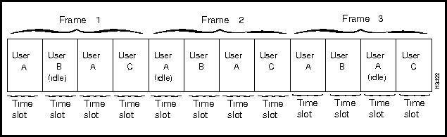
The time slots allocated for each user occur at precisely the same time in every frame. Since the time slots are synchronous, TDM is sometimes referred to as Synchronous Transfer Mode (STM).
Users can access the TDM communications channel only when time slots that have been allocated to them are available. For example, User A can send messages over the communications channel only during the time slot(s) designated for User A. If no traffic is ready to send when the designated time slot occurs, that time slot is unused. A user who sends a burst of traffic that exceeds the capacity of his or her designated time slots cannot use additional slots, even if those slots are idle. As a result, a long delay may occur before the remaining user traffic can be transferred over the network.
Over time, the continuing shift from analog to faster digital switches and the increased availability of fiber optic cable as a transmission medium have dramatically altered the nature of telecommunications networks. Such advances have fostered an increase in the size of such networks, improved the number and types of services offered, and enhanced the quality of those services.
Although important, these improvements do not provide the most efficient communications solution. For example, carrying nonvoice data over telecommunications networks is very inefficient, often requiring telecommunications users to purchase more dedicated bandwidth for their voice applications than they typically use on a daily basis.
ATM cell relay technology typically supports multiple traffic types (data, voice, and video), while addressing many of the pressing needs of both public and private network users, such as the following:
ATM is a connection-oriented data transmission service in which user information always traverses the same pre-established path or link between two network endpoints. Thus, ATM switches incorporate self-routing techniques for all cell relay functions in the network. This means that each ATM cell can find its way through the network switching fabric "on the fly," using routing information carried in the cell header.
However, the fact that ATM is a connection-oriented technology implies the need for ATM-specific signaling protocols and addressing structures, as well as protocols to route ATM connection requests across the network.
Nevertheless, because the ATM protocols are not tied to a particular transmission rate or physical transport medium, a communications application can operate at a rate appropriate to the physical layer technology in use. Furthermore, because ATM cell transmission is asynchronous in nature, delay-tolerant traffic (such as user data) can be freely intermixed with time-sensitive traffic (such as voice and video).
The fixed-size cell format of ATM enables cells to be switched (routed) through the network by means of high-speed hardware without incurring the increased overhead ordinarily associated with software or firmware in traditional packet routers.
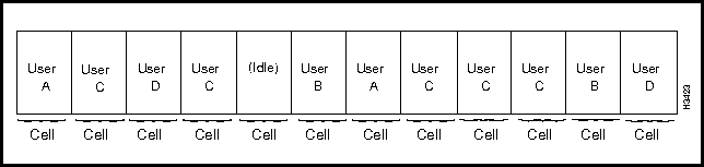
In ATM communications, access to the communications channel is much more flexible than is the case with TDM communications. Any ATM user needing the communications channel can gain access to it whenever it is available. Also, ATM imposes no regular pattern on the way users are granted access to the communications channel. ATM also provides bandwidth on demand.
In packet-handling technologies, such as High-Level Data Link Control (HDLC), any user can gain access to the communications channel, but a user who is sending a long message can prevent other users from gaining access to the channel until the entire message is sent. However, with ATM, every message is segmented into small, fixed-length cells that can be transported through the network on demand. Thus, no single user can monopolize the communications channel while other users have pending traffic.
Figure 1-2 illustrates the asynchronous nature of user traffic in an ATM network.
Figure 1-2 : User Assignments on ATM Communications Channel
ATM technology offers the following distinct benefits:
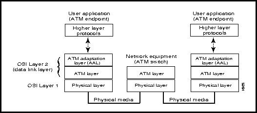
The ATM protocol uses a layered structure similar to that of the OSI Reference Model. The ATM reference model is illustrated in Figure 1-3. However, the ATM model differs from the OSI Reference Model in that the ATM model makes use of planes that operate across all three of its layers: the control plane, the user plane, and the management plane.
Figure 1-3 : ATM Reference Model
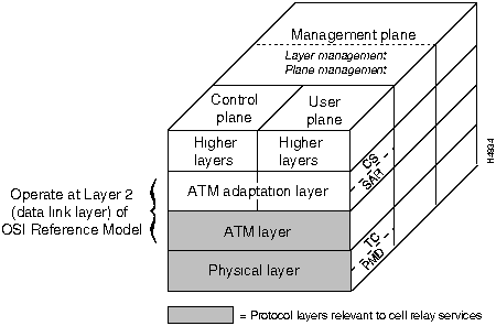
The user plane is for end-to-end data transfer. The control plane supports network-wide functions, such as the signaling used to establish switched virtual connections (SVCs) betweeen ATM endpoints. Finally, the management plane supports management and control functions for the network and its endpoints.
Once user data is packaged into ATM cells, the cells are transferred to the physical layer for placement onto a physical transport medium, such as fiber-optic cable or coaxial cable.
The process of placing cells onto the physical medium takes place in two sublayers of the physical layer: the physical medium dependent (PMD) sublayer, and the transmission convergence (TC) sublayer.
Each PMD sublayer is specific to a particular physical medium and includes definitions of proper cabling as well as bit timing. The TC sublayer generates and receives transmission frames and performs all overhead functions associated with the transmission frames. The TC sublayer performs a convergence function by receiving a bit stream from the PMD sublayer and extracting cells.
Although PMD sublayer operation depends on the physical medium being used, the following TC sublayer functions remain common to all physical layers:
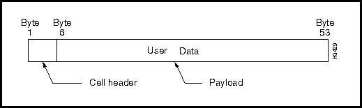
An ATM cell is a fixed-length unit of transmission defined by the ATM standard for all cell relay functions. Arranging data into fixed-length cells makes effective use of high-speed transmission media (such as T3 and E3 trunks), because fixed-length cells can be processed by hardware at electronic speeds without incurring any software overhead. Thus, transit delays for cells flowing through an ATM network are reduced or eliminated altogether.
An ATM cell is 53 bytes in length. The first 5 bytes constitute the cell header; the remaining 48 bytes constitute the payload (see Figure 1-4).
The cell header contains information for routing the cell through network nodes and ensuring that the cell reaches its destination. The payload is the informational substance of the cell itself.
Figure 1-4 : Format of UNI ATM Cell
The 5-byte header in the ATM cell is divided into fields that enable the cell to be routed through the network (see Figure 1-5). Table 1-1 describes these fields in detail.
Figure 1-5 : Format of UNI ATM Cell Header
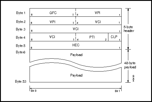
Table 1-1 : Fields in UNI ATM Cell Header
| Header Field Name | Location in Header | Description |
|---|---|---|
| GFC (generic flow control)1 | First four bits of Byte 1 | Controls the flow of traffic across the user network interface (UNI) and thus into the ATM network. |
| VPI (virtual path identifier) | Second four bits of Byte 1 and first four bits of Byte 2 | Identifies a particular virtual path connection (VPC). A VPC is a group of virtual connections between two points in the network which may involve several ATM links. VPIs provide a way to bundle ATM traffic moving to the same destination. |
| VCI (virtual channel identifier) | Second four bits of Byte 2, Byte 3, and first four bits of Byte 4 | Identifies a particular virtual channel connection (VCC). A VCC is a connection between two active, communicating ATM entities. The VCI consists of a concatenation of several ATM links. |
| PT (payload type) | The fifth, sixth, and seventh bits of Byte 4 | Indicates the type of information in the payload field. ATM cells carry different types of information that may require different handling by the network or terminating equipment. |
| CLP (cell loss priority) | Eighth bit of Byte 4 | Indicates the cell loss priority set by the user. This bit establishes the eligibility of the cell for discard by the network under congestion conditions. If the bit is set to 1, the cell can be discarded by the network if traffic congestion occurs. |
| HEC (header error control) | Byte 5 | Contains an error-correcting code calculated across the previous four bytes of the header. The HEC detects multiple-bit header errors and can be used to correct single-bit errors. The HEC provides protection against incorrect delivery of messages caused by address errors. The HEC does not provide any error protection for the ATM cell payload. |
| 1. For a network-to-node (NNI) interface, there is no GFC field. These four bits are used as part of the VPI field. | ||
Segmenting User Data into ATM Cells
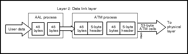
The processes that segment user data into ATM cells occur at Layer 2 of the OSI reference model. Layer 2 consists of two parts: the ATM adaptation layer (AAL) and the ATM layer (see Figure 1-6).
Once user data is segmented into ATM cells in Layer 2, the cells are conveyed to Layer 1, the physical layer, for transport through physical media and switching devices in the network to an ATM endpoint.
Figure 1-6 : Relationship of Data Link Layer to Physical Layer
The interacting entities comprising Layers 1 and 2 of the OSI reference model as they relate to ATM data processing are described in the following sections.
This section defines the traffic service classes supported by the ATM adaptation layer (AAL) and describes the data processing functions performed within the AAL. The AAL traffic service classes include the following:
Each of these generic traffic classes imposes certain processing requirements on the AAL. For example, depending on the type of traffic being handled, the AAL is required to complement the services provided by the ATM layer in order to properly proccess a specific type of user data being transmitted through the network.
Although all four generic traffic classes are described in this section, later discussions focus on AAL1 and AAL5, the two traffic classes relevant to the current ATM implementation for the LS2020.
The AAL traffic classes are categorized according to three basic attributes:
Given these attributes, the CCITT has defined the following AAL traffic service classes:
Table 1-2 summarizes the traffic service classes supported by the AAL.
Table 1-2 : Traffic Types Supported by ATM Adaptation Layer
| Traffic
Type |
Timing
Relationship |
Connection
Mode |
Bit Rate | Traffic Service Description |
| AAL1
(Class A) |
Synchronous | Connection-oriented | Constant | Provides circuit emulation and video services at a constant bit rate with bit streams ranging from a few kilobits to tens of megabits. This service, which supports flexible bit rate definition, consists of continuous (analog) signals. |
| AAL2
(Class B) |
Synchronous | Connection-oriented | Variable | Provides voice/video transmission services at a variable bit rate with timing synchronization between data senders and receivers. This kind of traffic is typically "bursty" in nature. |
| AAL3/4
(Class C) |
Asynchronous | Connection-oriented | Variable | Provides point-to-point or point-to-multipoint ATM cell relay services through connections established "on the fly" between data senders and receivers. This service handles multiple traffic types (data, voice, and video) in which data is arranged into ATM cells for efficient transport through LAN and WAN networks. This type of traffic is sensitive to data loss, but not to cell transport delay. |
| AAL 5
(Class D) |
Asynchronous | Connectionless | Variable | Provides very high-speed, packet-switched (LAN) or Frame Relay (WAN) transmission services, in which packets/frames typically contain sufficient addressing information for delivery to destinations without establishing prior connections between data senders and receivers. |
Functions of ATM Adaptation Layer
The ATM adaptation layer (AAL) provides an interface between higher layer protocols and the ATM layer proper. The primary function of the AAL is the segmentation and reassembly of higher layer data units and mapping the units into the fixed-length payload of ATM cells.
The AAL conveys and transforms user data from higher layer protocols to the ATM layer, and vice versa. AAL functions are typically implemented in the user's equipment, and the protocol information that AAL functions require for traffic processing are carried adjacent to the ATM cell payload.
The AAL performs functions required by the User, Control, and Management planes of the ATM reference model (see Figure 1-3). The AAL also supports the mapping of user data between the ATM layer and the next higher protocol layer.
The AAL supports multiple protocols to fit the traffic needs of different users. Thus, the AAL is service dependent. Also, the AAL isolates higher layer protocols from the specific characteristics of the ATM layer. The AAL does this by mapping the higher-layer protocol data units into the specific format of the information field in the ATM cell, and vice versa. Note also that the AAL exchanges information with other peer AAL entitities to support related AAL functions.
When passing user data received from a higher layer to the ATM layer, the AAL segments the data into 48-byte payloads. The ATM layer then adds a 5-byte header to each cell (see Figure 1-7). The resulting ATM cells are then passed to the physical layer for transport through the network over some physical medium. Conversely, when relaying cells received from the ATM layer to a higher layer protocol, the AAL reassembles the ATM data into a suitable format for presentation to the higher layer protocol. The process of arranging user traffic into ATM cells, and vice versa, in this manner is called cell segmentation and reassembly (SAR). The generalized flow of this process is illustrated in Figure 1-7.
Figure 1-7 : ATM Adaptation Layer (AAL) Functions
When an ATM cell is transferred through the network, it is processed in isolation from other ATM cells, and all routing decisions for individuals ATM cells are based on information carried within the ATM cell header. No processing of the data in the ATM payload field occurs.
Figure 1-8 shows the flow of ATM data in a network.
Figure 1-8 : Information Flow in ATM Network
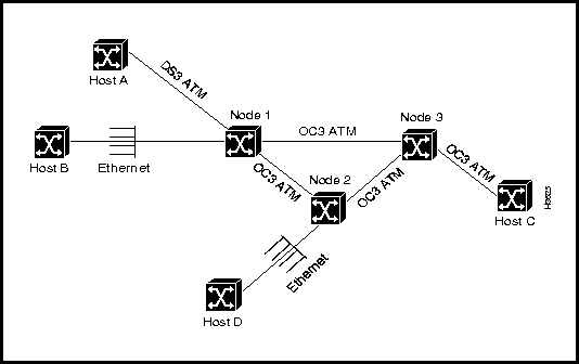
Hosts A and C are connected directly to the network through ATM interfaces, so they do all AAL processing internally. The network performs no AAL processing for hosts A and C.
Hosts B and D, however, are connected to native Ethernet interfaces on nodes 1 and 2, respectively. Therefore, node 2 performs all the AAL processing for host D, while node 3 performs no AAL processing.
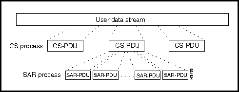
As noted earlier, the AAL processes user data according to defined traffic service classes, based on the timing relationships applicable to the service classes and the path connection types existing between the senders and receivers of data.
Traffic processing functions are accomplished in two logical sublayers of the AAL, as described below:
Figure 1-9 : Processing of User Data in ATM Adaptation Layer
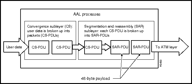
Figure 1-10 : Processing Relationships in ATM Adaptation Layer (AAL)
In AAL1 traffic processing, user data is transferred between communicating entities at a constant bit rate (CBR) after an appropriate virtual connection has been provisioned for such service. The AAL1 traffic services provided by the AAL include the following:
AAL1 CS Sublayer Functions
The functions of the CS sublayer depend on the particular AAL1 traffic services required and may involve some combination of the following:
AAL1 SAR Sublayer Functions
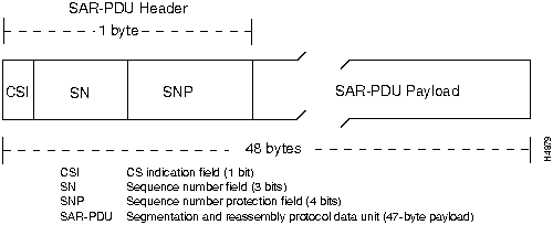
The SAR sublayer accepts a 47 byte block of data from the CS and adds a 1-byte SAR-PDU header to each data block to form a 48-byte SAR-SDU (service data unit), which, in effect, constitutes the 48-byte ATM cell). At the destination end of the connection, the SAR sublayer accepts the 48-byte cell from the ATM layer, strips off the 1-byte header, and passes the 47-byte cell payload to the CS.
Figure 1-11 shows the SAR-SDU format for processing AAL1 data.
In the course of traffic processing at the source endpoint, the SAR sublayer receives a 3-bit sequence number (SN) from the CS that is associated with each 47-byte payload. At the receiving end of the connection, this SN number is passed to the peer CS to detect the loss or misinsertion of SAR payloads during transmission.
The SAR sublayer also has the optional capability to indicate the existence of a CS sublayer. The SAR receives this indication through a 1-bit field called the CSI (CS indication) carried in the SAR-SDU header (see Figure 1-11). This CSI field is conveyed to the peer CS in the connection.
Both the SN and the CSI are protected against bit errors through a 4-bit sequence number protection (SNP) field also carried in the SAR-PDU header. This field enables both single-bit and multiple-bit error detection. If the SN and the CSI fields are corrupted and cannot be corrected, the CS is so informed.
Figure 1-11 : SAR-SDU Format for AAL1 Traffic Processing
The AAL5 traffic class provides a streamlined data transport service that functions with less overhead and affords better error detection capabilities. AAL5 is typically associated with variable bit rate (VBR) traffic and the emerging available bit rate (ABR) traffic type.
AAL5 CS Sublayer Functions
For purposes of processing AAL5 VBR data, the convergence sublayer is subdivided into two elements:
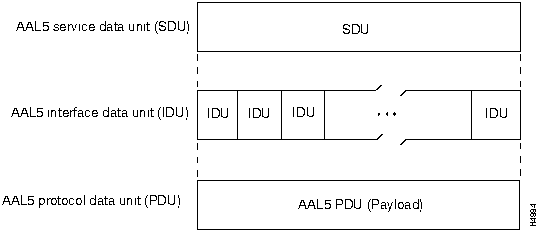
Figure 1-12 : AAL5 Message-Mode Transport Service
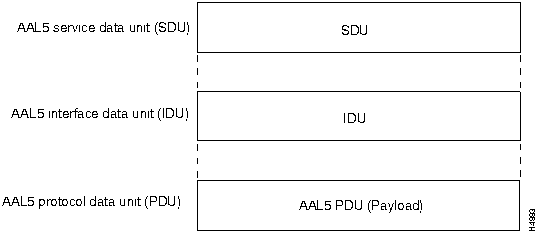
In streaming-mode service, the SDU is passed across the AAL5 interface in one or more IDUs. The transfer of these IDUs across the interface may occur separated in time. In other words, the streaming-mode service can "pipeline" the SDUs, that is, it can initiate the transfer of information to a peer AAL 5 entity before the complete SDU is available for transmission. Thus, in effect, all the IDUs belonging to a single SDU are transferred over the network as one or more AAL5 PDU payloads.
Figure 1-13 illustrates the AAL5 streaming-mode transport service.
Figure 1-13 : AAL5 Streaming-Mode Transport Service
AAL5 SAR Sublayer Functions
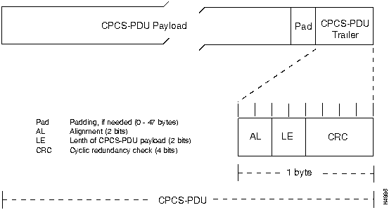
The AAL5 protocol enables the transport of variable-length data frames between communicating entities in an ATM network. Such frames contain from 1 to 65,535 octets. Figure 1-14 shows the format of the basic unit of information transfer for AAL5 traffic processing: the common part convergence sublayer protocol data unit (CPCS-PDU).
If needed, the CPCS-PDU payload is padded to align the resulting frame with an integral number of ATM cells. The padding field is used strictly for filler purposes and does not convey any user information.
During AAL5 processing, the CPCS-PDU trailer is appended to the payload to perform the following functions:
Figure 1-14 : CPCS-PDU Format for AAL5 Traffic Processing
The ATM layer functions as an interface between the AAL and the physical layer of the OSI Reference model. The ATM layer is responsible for two primary functions:
Thus, the basic purpose of the ATM layer is to provide for the transport of ATM cells between the ATM endpoints of a virtual connection in the network.
Conversely, if an ATM endpoint is sending data to another endpoint, the AAL takes the user data stream from a higher OSI layer and segments the data into 48-byte packets. The AAL passes the packets on to the ATM layer, which adds a 5-byte header to each packet to form a 53-byte ATM cell. The ATM layer then passes the stream of cells to the OSI physical layer for propagation through the network to the destination endpoint.
If the ATM layer is operating in conjunction with a network switching device (such as an LS2020 switch), the ATM layer determines where incoming cells are to be forwarded, resets the corresponding connection identifiers in the ATM cell header (the VPI or VCI fields) for the next link in the network, and forwards the cells appropriately.
The ATM layer also:
Figure 1-15 illustrates the procceses performed by the ATM layer for an outbound ATM cell.
Figure 1-15 : ATM Layer Processes
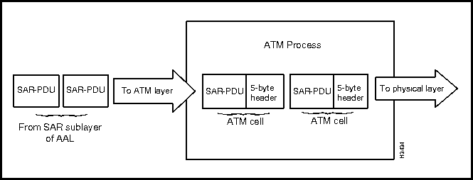
The ATM layer accepts the 48-byte SAR-PDUs from the SAR process, adds a 5-byte header to each SAR-PDU, and produces ATM cells for delivery to Layer 1 for transport through the network to an ATM endpoint.
The physical layer provides the ATM layer with access to the physical transmission medium. requires an interface to existing OSI physical layers. Physical layer functions include the following: These layers are defined in various existing network protocols.
Since ATM does not depend on any particular physical layer for data transport across a physical medium, you can build ATM networks using various physical interfaces and media types.
Connection Setup Through ATM Signaling
ATM signaling is the means by which an ATM endpoint sets up a connection through an ATM network to another ATM endpoint. To accomplish connection setup, signaling packets are sent from the source node to the destination node by means of a virtual channel reserved for ATM signaling purposes. This default signaling channel is well defined, and no other types of information can be transmitted across the channel.
All switches in an ATM network are preconfigured to receive any signaling packets sent across this default signaling channel and to pass them on to an associated signaling process within the switch. It is these internal signaling processes that set up the requested connection through the network.
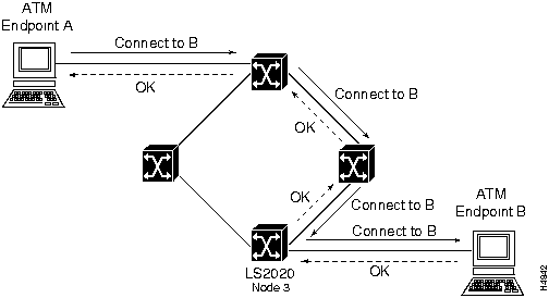
The signaling messages are routed through the network from switch to switch, setting up the connection identifiers as the connection request proceeds, until the destination endpoint is reached. The destination endpoint can either accept or reject the connection request. If the connection request is accepted, the data between the source endpoint and the destination endpoint flows along the newly-established path.
Figure 1-16 illustrates the message flow during an ATM connection setup request.
Figure 1-16 : Connection Setup by means of ATM Signaling
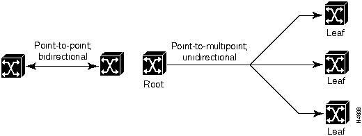
ATM is a connection-oriented, cell relay data transmission technology that requires a connection to be established between two communicating entities in the network before data transmission can occur. There are two fundamental types of connections in an ATM network:
These ATM connection types are illustrated in Figure 1-17.
Figure 1-17 : Types of ATM Connections
ATM supports all types of network traffic (data, voice, video, and image) by arranging information into fixed-length cells of 53 bytes for transmission (see the section entitled "ATM Cell Format"). These cells can be transported (switched) through the network at very high speeds through the use of industry-standard ATM interfaces and transmission protocols.
Routing information is carried in the header of each ATM cell. Thus, connections are readily established between communicating entities, enabling ATM cells to be sent (switched) to destinations anywhere in the network. Furthermore, network switching fabrics can transport multiple traffic types through the network transparently, and the ATM connections guarantee the delivery of cells to their destination(s) in proper sequence.
An overriding advantage of handling data as fixed-length ATM cells is that such an arrangement enables the network to accommodate not only rapid changes in the quantity of traffic, but also in the pattern of that traffic. Thus, an ATM network can simultaneously handle a mixture of bursty traffic and delay-sensitive traffic while providing services essential to other traffic types.
Consequently, ATM cell relay is generally regarded as the best multiplexing technology available for modern communication applications. It combines the strengths inherent in existing data communications and telecommunications technologies with unique ATM attributes.
This section describes how these ATM functions are accomplished.
The ATM switching technique involves the use of two fields in the ATM cell header:
These fields (shown in Figure 1-5 and described in Table 1-1) provide the necessary connection setup and routing information for the transport of ATM cells through any number of nodes in the network to their eventual destination.
Networks that do not use switching for data transport require that each packet (or cell) contain the explicit address of its destination. ATM, in contrast, uses switching for cell routing and transport because it is a simple, efficient technique that enables rapid cell switching along the entire data transmission path.
Basically, ATM switching works in the following manner:
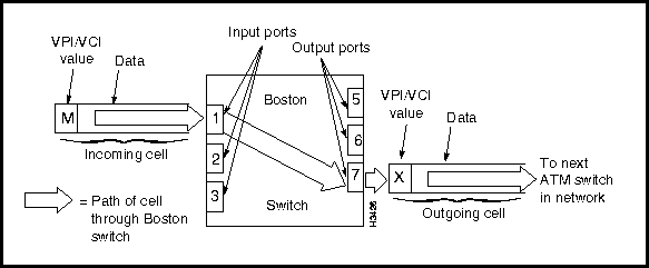
Suppose, for example, that your network includes a switch named "Boston." Suppose further that several data paths go through the Boston switch. When those data paths were created, an internal routing table was set up within the Boston switch. This routing table contains an entry for every data path going through that particular switch. Thus, the entries in the routing table map the incoming port and routing fields to outgoing port and routing fields for each data path. Table 1-3 shows these routing relationships.
Table 1-3 : Sample Routing Table in Boston Switch
| Port In | VPI/VCI
Value In |
Port Out | VPI/VCI
Value Out |
| 1 | L | 6 | Z |
| 1 | M | 7 | X |
| 2 | N | 7 | Y |
When the Boston switch receives an incoming cell on port 1 that carries designation M, it consults its internal routing table and finds that designation M needs to be replaced with designation X, and, further, that the cell must be passed out of the switch on port 7. Thus, the outgoing cell is transported to the next switch in the network, namely, the switch connected to port 7 of the Boston switch. This switching and table lookup process is illustrated in Figure 1-18.
Figure 1-18 : ATM Cell Passing through Boston Switch
In general, the cell transport process can be summarized as follows:
This process continues across constituent network links until the ATM cell reaches the destination endpoint.
In accomplishing cell transport functions, ATM technology make use of networking constructs called virtual channel connections (VCCs) and virtual paths (VPs). These constructs are described in the next section.
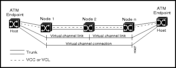
Virtual Channels and Virtual Channel Connections
A virtual channel (VC) is a logical circuit created to ensure reliable ATM communications between two endpoints in an ATM network. For purposes of ATM cell transmission through the network, a virtual channel connection (VCC) can be regarded as an end-to-end connection for a single data flow between two network nodes. A vitual channel is identified by the combination of the VPI field and VCI field in the ATM cell header (see Figure 1-5).
ATM networking requires that you establish associations or connections between ATM endpoints. Because ATM is a connection-oriented technology, no information can be transferred from one endpoint in the network to another until a connection between them has been established.
Such connections can be established on demand, which is the typical situation for a switched ATM service in a private network. Alternatively, such connections can be pre-provisioned, or assigned beforehand, as is often done in public networks.
Typically, a VCC in an ATM network consists of a connected series of virtual channel links (VCLs), each of which serves as a means of bidirectional transport of ATM cells. The virtual channel identifier (VCI) in each ATM cell header identifies the VCL through which a cell must pass and determines where the cell should be sent next.
Consequently, a concatenation of VCLs, in effect, sets up a mechanism through which ATM cells can flow between two communicating endpoints in the network. A connection from a local LS2020 switch to a central office that, in turn, is connected to another LS2020 switch is an example of a simple two-link VCC.
Figure 1-19 shows a VCC comprising multiple VCLs.
Figure 1-19 : VCLs as Elements of VCCs
All communications between two endpoints in an ATM network can occur by means of the same VCC. Furthermore, such a connection preserves the sequence of ATM cells being transmitted between the ATM endpoints and guarantees a certain level or quality of service. ATM cells may also be transported within virtual paths (VPs), as described in the next section.
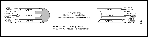
Virtual Paths and Virtual Path Connections
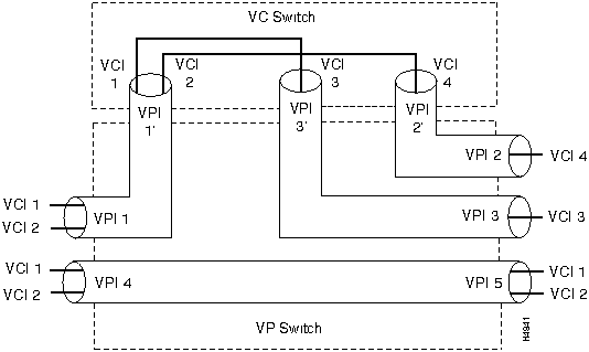
A virtual path (VP) is a logical grouping of virtual connections (VCs) that connect two communicating endpoints in an ATM network. Thus, you can think of a virtual path as a bundle of virtual circuits. A VP is identified solely by the VPI field in the ATM cell header (see Figure 1-5); the VCI field is ignored.
In effect, a VP is a "large pipe" that you can use in a desired way for data transmission. For example, you can use internal signaling over a VP to create numerous virtual circuits within the VP that are entirely transparent to the network services provider.
From the network's viewpoint, an ATM cell flowing through the network is either a VP cell or a VC cell. If a cell traversing the network is a VP cell, the network pays attention to the VPI field in the cell header; similarly, if a cell traversing the network is a VC cell, the network pays attention to the VCI field. Thus, cells flowing between network endpoints can be either VP cells or VC cells.
Two fundamental advantages derive from the presence of VPs in a network:
From a practical standpoint, the advantage of VPs in an ATM network is that they enable cell streams from multiple users to be grouped together into a higher-rate signal on the physical link for transport through the network. Figure 1-20 illustrates this principle.
Thus, VPs constitute a convenient way of bundling network traffic being directed to the same destination(s) or traffic that requires the same quality of service (QoS). Because of these factors, VPs are commonly established in an ATM network for trunking purposes.
Figure 1-20 : Virtual Channels Transported within Virtual Paths
Virtual Connection Switching and Virtual Path Switching
Figure 1-21 illustrates the logical flow of ATM traffic in a network during virtual channel (VC) switching and virtual path (VP) switching. In VC switching, the network pays attention to the individual connections ("wires") in the pipe and directs network traffic accordingly; in VP switching, the network pays attention to the traffic in the pipe as a whole.
Figure 1-21 : Virtual Channel and Virtual Path Switching
This section describes the ATM UNI signaling protocol, the UNI interface types, and the ATM UNI addressing scheme used in establishing connections in an ATM network.
A standard UNI signaling protocol is used to dynamically establish, clear, and maintain VCCs in an ATM network. In UNI signaling, control functions and data flow are coordinated through message traffic exchanged between the ATM source and destination endpoints. The connections set up through these signaling protocols are commonly referred to as switched virtual connections (SVCs).
ATM UNI signaling uses a "one-pass" model for connection setup that is common to all telecommunications networks. In this model, a connection setup request is accomplished in a manner similar to making an ordinary telephone call. In other words, from a source endpoint in the network, a connection request is initiated and propagated through the network, setting up the path through the network as the request proceeds, until the destination endpoint is reached.
The destination endpoint may then choose to accept or reject the connection request. If the destination node accepts the connection request, it sends a connect message back through the network along the same path to the requesting source endpoint. Once the source endpoint receives and acknowledges the connect message, either endpoint can start transmitting data by means of the connection.
If the destination endpoint rejects the connection request, it returns a release message to the source endpoint, clearing the connection as it proceeds through the network. Similarly, release messages may be used by either the source or destination endpoint to clear an existing connection.
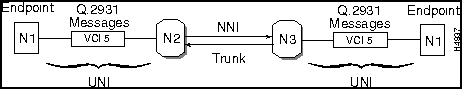
In this one-pass connection model (see Figure 1-22), VPI 0 and VCI 5 are used as the default signaling channel for initiating all ATM connection requests in the network. In other words, this virtual channel is reserved exclusively for ATM signaling traffic, and no other types of information can be sent on this virtual channel. Furthermore, all ATM switches in the network are preconfigured to receive any signaling packets sent across this virtual connection and to pass them on to a signaling process associated with the switch.
Hence, using the VPI 0 and VCI 5 connection identifiers, you can, in effect, initiate a connection request to a telephone number associated with another node elsewhere in the network. These connection identifiers are always allocated in each direction of a connection. Thus, you get a response from that number stating that a connection has been made. At this point, the resulting SVC functions much like a PVC in terms of cell transport through the network.
Figure 1-22 : UNI Signaling VCC Setup
When either the source node or the destination node decides that it wants to tear down the existing SVC, the VPI 0 and VCI 5 connection identifiers again constitute the virtual channel used for making known the tear-down request between the two communicating endpoints.
The ATM signaling protocols vary according to the type of ATM link being set up:
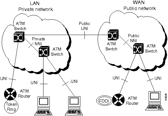
Figure 1-23 illustrates these types of interfaces in an ATM network.
Figure 1-23 : ATM Network Interfaces
In general, the purpose of ATM signaling protocols is to set up switched virtual connections (SVCs) between communicating entities in an ATM network. For the purposes of this document, the existing ATM UNI 3.0/3.1 standards apply. For ATM network-to-network signaling purposes, however, the formal ATM P-NNI Phase 1 standard is still under development.
The ATM Forum UNI 3.0/3.1 signaling protocol specification makes an important contribution to internetworking through its addressing scheme. This scheme allows the signaling protocol to identify the sources and destinations of connections in an ATM network.
Historically, the ITU-T chose to use telephone number-like E.164 addresses as the addressing structure for public ATM Broadband Integrated Services Digital Networks (B-ISDN). Since E.164 addresses are a public (and therefore expensive) resource and cannot typically be used within private networks, the ATM Forum extended ATM addressing to include private networks. In developing such a private network addressing scheme for UNI 3.0/3.1 signaling purposes, the ATM Forum evaluated two fundamentally different addressing models:
For practical reasons, the ATM Forum chose the subnetwork or overlay addressing model for UNI 3.0/3.1 signaling purposes.
Although the peer addressing model would simplify the administration of network endpoint addresses, it would also greatly increase the complexity of ATM switches, since they would be required to act as multiprotocol routers and to support address tables for all current protocols, as well all of their own existing protocols. Furthermore, current routing protocols, having been developed originally for LAN and WAN networks, do not map well to ATM requirements, nor do they allow the use of ATM's unique quality of service (QoS) attributes.
Most importantly, however, by decoupling ATM from other higher layer protocols, the overlay model allows each layer to be developed independently from another layer. From a practical standpoint, this layer independence is extremely important. Since ATM and higher layer protocols are complex in and of themselves, coupling their development would have adversely affected the general deployment of ATM in commerce and industry.
Having chosen the overlay model, the ATM Forum defined an address format for private networks based on the syntax of an OSI Network Service Access Point (NSAP) address. This address format is described in the section below entitled "ATM Private Network Address Formats."
Note, however, that an ATM address is not equivalent to an NSAP address, despite their structural similarity. In common usage, ATM addresses are often referred to as "NSAP addresses." But ATM addresses are better described as ATM private network addresses, or ATM endpoint identifiers, since they identify subnetwork points of attachment, not NSAP addresses per se.
ATM Private Network Address Formats
The 20-byte address formats shown in Figure 1-24 are designed for use within private ATM networks, while public networks typically use E.164 addresses that are formatted as defined by ITU-T. The ATM Forum did, however, specify an NSAP encoding for E.164 addresses that can be used in private networks. Such private networks may base their own NSAP format addressing on the E.164 address of the public UNI to which they are connected.
Figure 1-24 : ATM Private Network Address Formats
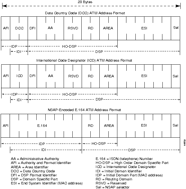
Note that the three addressing formats illustrated in Figure 1-24 differ only with respect to the AFI (Authority and Format Identifier) field and the Initial Domain Identifier (IDI) field. These three addressing formats are described briefly below:
|
|
Copyright 1988-1996 © Cisco Systems Inc.