|
|

Cisco 7507 Public Network Certification
This publication provides international agency compliance, safety, and statutory information for wide area network (WAN) interfaces for the Cisco 7507 router. This information is to be used in conjunction with the Cisco 7507 Hardware Installation and Maintenance publication and as an addendum to the Router Products Getting Started Guide.
This publication also supplements information in the Fast Serial Interface Processor (FSIP) and Multichannel Interface Processor (MIP) configuration notes.
The following sections are included in the publication:
The Cisco Systems FSIP with E1-G.703/G.704 port adapter is a chassismounted processor/interface card for use within a range of data communication (gateway and router) chassis supplied by Cisco Systems. The FSIP with E1-G.703/G.704 is a self-contained product that provides all of the hardware and software necessary to allow connection of Cisco Systems' chassis to digital leased line circuits (point to point) using CCITT recommendation G.703 operating protocols at speeds up to 2 Mbps. The FSIP with E1-G.703/G.704 is fully transportable between compatible host chassis. The choice of each compatible chassis has no effect on capabilities, functionality, or performance of the FSIP with E1-G.703/G.704.
The FSIP with E1-G.703/G.704 consists of the following subassemblies:
The FSIP with E1-G.703/G.704 provides capacity for the installation of up to four E1-G.703/G.704 adapter cards providing a maximum of eight serial port connections. Each port can provide connection to 2-Mb leased lines. Combined, the FSIP and E1-G.703/G.704 adapter cards provide all of the hardware necessary for supporting leased line communications.
Each port on the E1-G.703/G.704 port adapter is presented as a 15-pin, D-type connector. Each port is configured at the factory to offer either 75-ohm termination impedance for unbalanced operation or 120-ohm termination impedance for balanced operation. The E1-G.703/G.704 port adapter cable used is dependent on the impedance configuration. Further configuration is not necessary.
Each adapter cable provides a D-type connector to the applicable standard interface connector. Custom adapter cables must be ordered as follows:
![]()
The E1-G.703/G.704 port adapter is not intended to be used in a home environment, due to possible radio interference it might cause.
The E1-G.703/G.704 port adapter should not be connected to cabling that would be required by European Standard/Normative EN60950:1993 to be equipped with over-voltage protection. Only cables supplied by Cisco Systems should be used.
The E1-G.703/G.704 port adapter maintains bit integrity between the Network Port and the FSIP.
The worst-case delay through the E1-G.703/G.704 port adapter is 125 microseconds (∝S).
Except for Australia, the following port is designated Safety ExtraLow Voltage (SELV) within the scope of EN60950:1993:
The FSIP contains SELV circuitry. Ensure that attachments at the interconnection ports of the apparatus are also SELV circuits. SELV circuits are so designed and protected that, under both normal conditions and a likely fault condition, the voltage that can be drawn is not hazardous.
Always disconnect the chassis from the power supply before removing any covers.
Always disconnect the host product chassis from any analogue telephone circuits, basic access, or primary access Integrated Services Digital Network (ISDN) before removing any screws.
Failure to install the FSIP with E1-G.703/G.704 in accordance with these instructions will invalidate the approval.
If you have any doubt as to how to safely install the FSIP with E1-G.703/G.704 correctly within a host chassis, seek advice from a qualified telecommunications engineer or your local Cisco Systems sales office.
Except in Australia, users are reminded that this port should only be connected to SELV ports on other equipment in accordance with EN60950 clause 2.3. The FSIP serial interface is designated a SELV port within the scope of EN41003.
This apparatus is intended for use when powered by the FSIP card. The power supply used to power the FSIP is approved to EN41003 and EN60950 producing a SELV output in accordance with EN60950 clause 2.3. The power requirement for the FSIP with E1-G.703/G.704 port adapters installed is 1300 milliamperes (mA) at +5 volts direct current (VDC).
It is important to ensure that the power drawn by the apparatus, together with any auxiliary apparatus, lies within the rating of the host power supply.
The Cisco Systems FSIP with 5-in-1 port adapter assembly is a processor/interface card assembly for use within a range of data communication (gateway and router) chassis supplied by Cisco Systems Europe. The FSIP assembly is a self-contained product that provides all of the hardware and software necessary to allow connections of Cisco Systems' chassis to either digital leased line circuits (point to point) or to Packet Switched Public Data Networks (PSPDN).
The FSIP assembly is fully transportable between compatible host chassis. The choice of each compatible chassis has no effect on the capabilities, functionality, or performance of the FSIP assembly.
The FSIP assembly consists of the following subassemblies:
The FSIP card is a self-contained telecommunication device that provides up to four 5-in-1 serial port adapters providing a maximum of eight serial port connections. Each port can provide connection to leased lines on packed switched services of the type X.21, V.24, V.35, and V.36. Combined, the FSIP and 5-in-1 serial port adapter cards provide all of the hardware necessary for supporting PSPDN communications. The wide-area network (WAN) operating software is resident on the route processor card.
Each port of the 5-in-1 serial port adapter is presented as a custom 50way connector. The following port configurations are supported:
The final configuration of each serial interface is dependent on the serial port adapter cable used. The FSIP incorporates cable sensing circuitry to detect the presence of a specific cable for each service. Further configuration is not necessary. Custom cables are supplied with the apparatus and are as follows:
Each cable provides adaption from a 50way custom connector to the applicable ISO standard connector.
The CE168 marking on the chassis rear panel signifies that the 5-in-1 port adapter meets the European Directive 91/263/EC and has been designed to NET1 and NET2 standards. The marking is shown in Figure 1.
![]()
X.25 packet-switched support is provided by the operating software resident on the route processor card. This software is designated as the Cisco FSIP, X.25 Version 2.0. This software provides both the link and packet level facilities of the FSIP assembly.
The operating software is accessed via a VT100 terminal connected to the console port of the route processor card. The settings of the terminal should be as follows:
To boot the software, type the following command at the ">" prompt:
(The software will now boot from Flash memory.)
The FSIP assembly contains Safety Extra-Low Voltage (SELV) circuitry. Ensure that attachments at the interconnection ports of the apparatus are also SELV circuits. (SELV circuits are so designed and protected that, under both normal conditions and a likely fault condition, the voltage that can be drawn is not hazardous.)
Always disconnect the chassis from the power supply before removing any covers.
Always disconnect the host product chassis from any analogue telephone circuits or basic access ISDN (where applicable) before removing any covers.
Failure to install the FSIP assembly in accordance with these instructions will invalidate the approval.
If you have any doubt as to how to safely install the Cisco FSIP assembly correctly within a host chassis, please seek advice from a qualified telecommunications engineer.
The power requirements of the FSIP card (with 5-in-1 serial port adapter cards installed) are as follows:
The power requirements of the route processor card are as follows:
The power requirements of the switch processor card are as follows:
It is important to ensure that the power drawn by the apparatus, together with any auxiliary apparatus, lies within the rating of the host power supply.
The Cisco Systems PRI-MIP port adapter is a daughter card connected to a chassis-mounted processor/interface card (MIP) for use within a range of data communication (gateway and router) chassis supplied by Cisco Systems. The PRI-MIP is a self-contained product that provides all of the hardware and software necessary to allow connection of the Cisco 7507 to structured digital leased line circuits (point-to-point) using CCITT recommendation G.703/704 operating at 2 Mbps. The card can also be used on an open structured lease line; however, the framing cannot be disabled. The PRI-MIP is also NET5 compliant for use on Primary Rate ISDN circuits operating at 2 Mbps. The PRI-MIP is fully transportable between compatible host chassis. The choice of each compatible chassis has no effect on capabilities, functionality, or performance of the PRI-MIP.
The PRI-MIP consists of the following subassembly:
The PRI-MIP provides capacity for a maximum of two independent serial port connections. Each port can provide connection to 2-Mb leased lines or Primary Rate ISDN.
Each port on the PRI-MIP port adapter is presented as a 15-pin, D-type connector. Each port is configured at the factory to offer either 75-ohm termination impedance for unbalanced operation or 120-ohm termination impedance for balanced operation. The PRI-MIP port adapter cable used is dependent on the impedance configuration. Further configuration is not necessary. Each adapter cable provides a D-type connector to the applicable standard interface connector. Custom adapter cables must be ordered as follows:
The PRI-MIP port adapter should not be connected to cabling that would be required by European Standard/Normative (EN)60950:1992 to be equipped with over-voltage protection. Only cables supplied by Cisco Systems should be used.
The PRI-MIP port adapter is approved to British Approvals Board of Telecommunications (BABT) Oftel Technical Requirement OTR.001 with a port type of 2DS (telephony traffic carried) or 5C (non-telephony traffic carried), which allows connection to the public 2048-kilobits per second (kbps) network presented with a G.703 interface.
The PRI-MIP port adapter maintains bit integrity between the Network Port and the MIP mother card.
The worst-case delay through the PRI-MIP port adapter is 125 microseconds (∝S).
When the PRI-MIP is configured for 120-ohm balance operation, the CE168 marking (shown in Figure 1 on page 4) signifies that this product meets the European Directives 94/821/EC and 94/796/EC. In the 75-ohm configuration, the PRI-MIP is in compliance with the UK national standard OTR 001.
Except for Australia, the PRI-MIP port is designated Safety ExtraLow Voltage (SELV) within the scope of EN60950:1993.
The PRI-MIP contains SELV circuitry. Ensure that attachments at the interconnection ports of the apparatus are also SELV circuits. SELV circuits are so designed and protected that, under both normal conditions and a likely fault condition, the voltage that can be drawn is not hazardous.
Always disconnect the chassis from the power supply before removing any covers.
Always disconnect the host product chassis from any analogue telephone circuits, primary access, or basic access Integrated Services Digital Network (ISDN) before removing any screws.
Failure to install the PRI-MIP in accordance with these instructions will invalidate the approval.
If you have any doubt as to how to safely install the PRI-MIP correctly within a host chassis, seek advice from a qualified telecommunications engineer or your local Cisco Systems sales office.
Note that the host chassis should be connected to earth ground during normal use.
The PRI-MIP port adapter card derives its power from the MIP mother card. The power supply used to power the apparatus is approved to EN41003 and EN60950 producing a SELV output in accordance with EN60950 clause 2.3. The power requirement for the PRI-MIP port adapters installed is 1 ampere (A) at +5 volts direct current (VDC).
It is important to ensure that the power drawn by the apparatus, together with any auxiliary apparatus, lies within the rating of the host power supply.
This section describes special installation requirements for the following assemblies:
Where applicable, these assemblies are approved only for installation in a host and with host attachments, which are either type approved for such apparatus or covered by a General Approval. Except at the edge connector, which plugs into the host's expansion slot, clearance and creepage distances of X millimeters (mm) and Y mm, as listed in Table 1, must be maintained between the cards and other parts of the host including any other expansion cards fitted.
Creepage distance is defined as the minimum distance between two points (following the contour of the insulator) measured across the surface of an insulator. Clearance distance is defined as the minimum distance between two points (line of sight) measured in air.
Table 1 Creepage and Clearance Distances Based on Voltage
| Voltage Used or Generated by Other Parts of the Host or Expansion Card (Vrms(1) or VDC(2)) | Creepage (Y mm)(3) | Clearance (X mm) |
|---|---|---|
| Up to 50 | 2.4 (3.8) | 2.0 |
| Up to 125 | 3.0 (4.8) | 2.6 |
| Up to 250 | 5.0 (8.0) | 4.0 |
| Up to 300(4) | 6.4 (10.0) | 4.0 |
Clearance and creepage distances are measured between adjacent parts, as shown in Figure 2.
Figure 2 Creepage and Clearance Distance Measurements
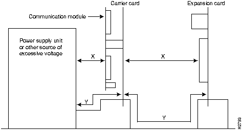
Note that in Figure 2, X indicates the clearance distances between the cards and between adjacent cards and components, and Y shows the creepage path across the surface of an insulator and between the two points indicated by X.
The following operating conditions are required within the European Community:
The ports marked "Ethernet," "10BaseT," "TokenRing," "FDDI," "Console," and "AUX" are SELV circuits. SELV circuits should only be connected to other SELV circuits.
The ports marked "Ethernet," "10BaseT," "TokenRing," "FDDI," "Console," and "AUX" have a safety warning applied to them as follows:
"These ports do not provide isolation sufficient to satisfy the requirement of EN60950:1992; apparatus connected to these ports should either have been approved to EN60950:1992 or have previously been evaluated against plc (Post Office) Technical Guides 2 or 26 and given permission to attach; any other usage will invalidate any approval given to this apparatus."
Connection of power supply: the Cisco 7507 is intended for use when supplied with AC power from a supply providing 100 through 240 VAC, 50 through 60 Hz, 12A through 6A or when supplied with DC power from a supply rated 40 through 72 VDC, 24 through 13A.
Other usage will invalidate any approval given to this apparatus if as a result it ceases to comply with EN60950:1992.
![]()
Cisco Connection Online (CCO) is Cisco Systems' primary, real-time support channel. Maintenance customers and partners can self-register on CCO to obtain additional content and services.
Available 24 hours a day, 7 days a week, CCO provides a wealth of standard and value-added services to Cisco's customers and business partners. CCO services include product information, software updates, release notes, technical tips, the Bug Navigator, configuration notes, brochures, descriptions of service offerings, and download access to public and authorized files.
CCO serves a wide variety of users through two interfaces that are updated and enhanced simultaneously---a character-based version and a multimedia version that resides on the World Wide Web (WWW). The character-based CCO (called "CCO Classic") supports Zmodem, Kermit, Xmodem, FTP, Internet e-mail, and fax download options, and is excellent for quick access to information over lower bandwidths. The WWW version of CCO provides richly formatted documents with photographs, figures, graphics, and video, as well as hyperlinks to related information.
You can access CCO in the following ways:
http://www.cisco.com.
cio.cisco.com.
For a copy of CCO's Frequently Asked Questions (FAQ), contact
ciohelp@cisco.com.
For additional information, contact
cioteam@cisco.com.
tac@cisco.com.
To obtain general information about Cisco Systems, Cisco products, or upgrades, contact 800 553-6387, 408 526-7208, or
csrep@cisco.com.
|
|
Copyright 1988-1995 © Cisco Systems Inc.