|
|

Cisco 7200 Series Port Adapter Hardware Configuration Guidelines
Product Numbers: CISCO7206, CISCO7206-DC, CISCO7204, CISCO7204-DC
This document explains the port adapter hardware configuration guidelines for the Cisco 7200 series routers. It includes brief explanations of the Cisco 7200 series architecture, port adapter bandwidths, and port adapter slot numbering.
The following section are included in this document:
The Cisco Internetwork Operating System (Cisco IOS) software running your router contains extensive features and functionality. The effective use of many of these features is easier if you have more information at hand.
Cisco documentation and additional literature are available on a CD-ROM called Cisco Connection Documentation, Enterprise Series, which ships with your chassis. The CD is updated and shipped monthly, so it might be more up to date than printed documentation. To order additional copies of the Cisco Connection Documentation, Enterprise Series CD, contact a Cisco Sales or Customer Service representative. You can also access Cisco technical documentation on the World Wide Web URL http://www.cisco.com.
For additional information on configuring the Cisco 7200 series routers, the following documentation resources are available to you:
The Cisco 7200 series consists of the four-slot Cisco 7204 and the six-slot Cisco 7206. The Cisco 7200 series routers support multiprotocol, multimedia routing and bridging with a wide variety of protocols and any combination of Ethernet, Fast Ethernet, Token Ring, Fiber Distributed Data Interface (FDDI), and serial media. Network interfaces reside on port adapters that provide a connection between the routers' three Peripheral Component Interconnect (PCI) buses and external networks. Port adapters can be placed in any available port adapter slot, in any desired combination.
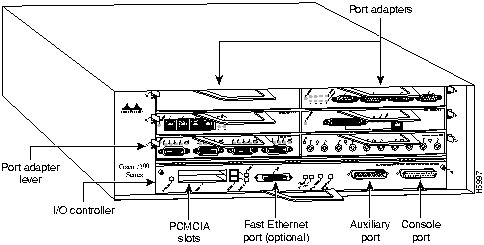
The front of the Cisco 7200 series routers provides access to an Input/Output (I/O) controller and up to four or six network interface port adapters. The I/O controller has a local console port for connecting a data terminal (or data terminal equipment [DTE]) and an auxiliary port for connecting a modem (or other data communications equipment [DCE]) or other devices for configuring and managing the router; two Personal Computer Memory Card International Association (PCMCIA) slots for Flash memory cards; and an optional Fast Ethernet port. The Fast Ethernet port provides a 100-Mbps connection to the network. Figure 1 shows the Cisco 7204. Figure 2 shows the Cisco 7206.
Figure 1 : Cisco 7204---Front View
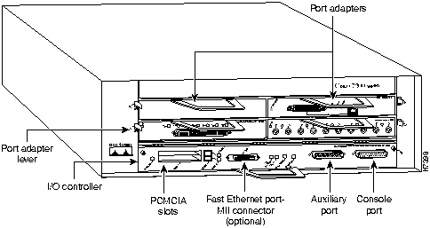
Figure 2 : Cisco 7206---Front View
The port adapters installed in the Cisco 7200 series routers are of the same type as those installed on the second-generation Versatile Interface Processors (VIP2s) in the Cisco 7000 family routers. The port adapters installed in the Cisco 7200 series routers support online insertion and removal (OIR).
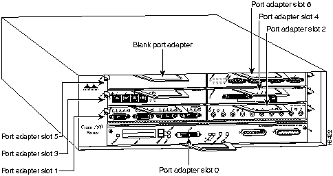
Port adapter slots in the Cisco 7200 series are numbered from left to right, beginning with port adapter slot 1 and continuing through port adapter slot 4 for the Cisco 7204, and slot 6 for the Cisco 7206. Port adapter slot 0 is the Fast Ethernet port on the I/O controller. Figure 3 shows the port adapter slot numbering for the Cisco 7206.
Figure 3 : Port Adapter Slot Numbering---Cisco 7206 Shown
The rear of the Cisco 7200 series routers provides access to the network processing engine and up to two 280W, AC-input or DC-input power supplies (refer to Figure 4).
Figure 4 : Cisco 7200 Series Router---Rear View
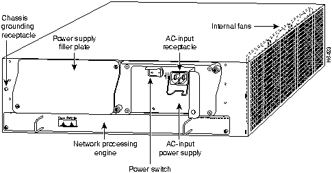
The network processing engine has no external connectors or LEDs. There are two handles for removing and installing the network processing engine and two captive installation screws for securing it to the chassis.
A fully configured Cisco 7200 series router operates with only one installed power supply; however, a second, optional power supply provides hot-swappable, load-sharing, redundant power. The power supply has the router's main power switch and either an AC-input power receptacle, or a hardwired DC-input power cable (depending on the type of installed power supply). Adjacent to the power supply bays there is a 10 x 32-inch chassis ground receptacle that provides a chassis ground connection for ESD equipment or a grounding wire (refer to Figure 4).
Three internal fans draw cooling air into the chassis interior and across internal components to maintain an acceptable operating temperature (refer to Figure 4). The three fans are enclosed in a tray that is located in the subchassis.
The I/O controller, port adapters, power supplies, and network processing engine slide into their respective chassis slots and connect directly to the router's midplane; there are no internal cables to connect. The midplane distributes DC power from the power supplies to the I/O controller, port adapters, fan tray, and network processing engine.
The port adapters in the Cisco 7200 series routers provide the connection between the routers' three Peripheral Component Interconnect (PCI) buses, called mb0, mb1, and mb2, and external networks. Bus mb0 is for the optional Fast Ethernet port on the I/O controller, bus mb1 is for port adapter slots 1, 3, and 5, and bus mb2 is for port adapter slots 2, 4, and 6. The port adapters are categorized as high, medium, and low bandwidth. The high and medium bandwidth port adapters should be evenly distributed between bus mb1 and bus mb2.
Figure 3 shows the port adapter slot numbering for the Cisco 7206. Figure 5 shows the port adapter slot numbering for the Cisco 7204. Table 1 lists port adapter types and bandwidths.
Figure 5 : Port Adapter Slot Numbering---Cisco 7204 Shown
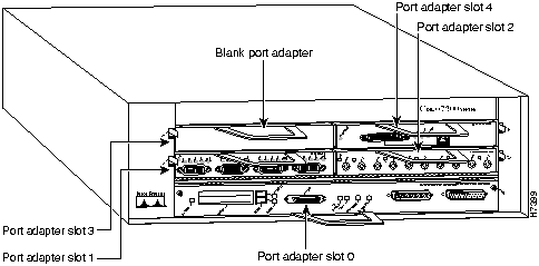
Table 1 : Port Adapter Types and Bandwidths
| Port Adapter Type | Product Name | Bandwidth |
|---|---|---|
| Fast Ethernet 100BASE-TX | PA-FE-TX | High |
| Fast Ethernet 100BASE-FX | PA-FE-FX | High |
| Multimode FDDI | PA-FDDI-MM | High |
| Single -mode FDDI | PA-FDDI-SM | High |
| 2-port High-Speed Serial | PA-2H | High |
| 1-port High-Speed Serial | PA-H | High |
| 8-port Ethernet 10BASE-T | PA-8E | Medium |
| 5-port Ethernet 10BASE-FL | PA-5EFL | Medium |
| 4-port Ethernet 10BASE-T | PA-4E | Medium |
| 4-port Token Ring | PA-4R | Medium |
| 4-port Synchronous Serial | PA-4T | Low |
To ensure your Cisco 7200 series port adapter configuration is sufficient for average network data traffic patterns, follow these guidelines (keeping in mind that the Fast Ethernet port on the I/O controller, if present, is considered a high bandwidth port adapter):
The system will prompt you with a message if your port adapter configuration does not follow the above guidelines. You may choose to redistribute the port adapters in your Cisco 7200 series router according to the guidelines in this document, or carry on with your current port adapter configuration. A Cisco 7200 series router will operate with an unbalanced port adapter configuration; however, we recommend balancing your configuration.
|
|
Copyright 1988-1996 © Cisco Systems Inc.