|
|
Maintaining the Cisco AS5200 Universal Access Server
This appendix contains information about maintenance procedures that you might need to perform on the Cisco AS5200 as your internetworking needs change.
This appendix contains the following sections:
![]()
You can install feature cards in the Cisco AS5200 without removing the chassis cover. Each Cisco AS5200 chassis can accommodate up to three feature cards. The choice of feature cards is as follows:
A blank slot cover must be installed over unused slots.
Perform the following steps to install a Cisco AS5200 feature card:
Figure A-1 : Installing a Feature Card
Installing a 12-Port Modem Card
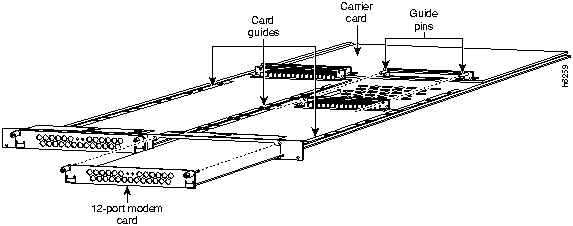
You can add a 12-port modem card to a carrier card installed in the Cisco AS5200. The modem card can be installed in the carrier card without removing the carrier card from the chassis.
You need the following tools to install the 12-port modem card:
The installation of the 12-port modem card is shown in Figure A-2. The carrier card is shown removed from the Cisco AS5200 to show the installation of the 12-port modem card in the carrier card.
Figure A-2 : 12-Port Modem Card Installation Perform the following steps to install a 12-port modem card:
This section describes the procedure for opening the chassis by removing the chassis cover.
You need the following tool to open the chassis:
You must open the Cisco AS5200 chassis to gain access to its interior components: the system card, system-code single in-line memory modules (SIMMs), dynamic random access memory (DRAM) SIMMs, and boot ROM. When you replace the Boot ROMs, you must also remove of all feature cards in the chassis.
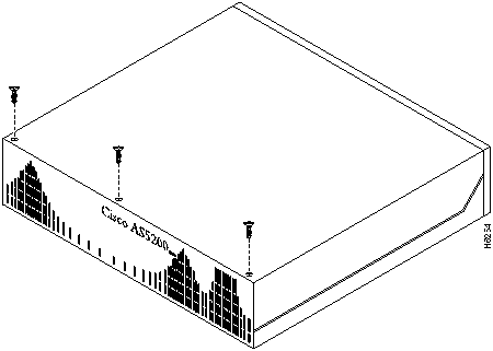
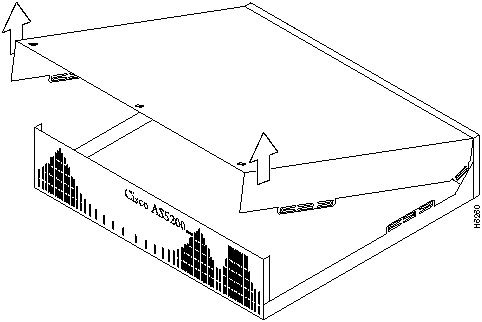
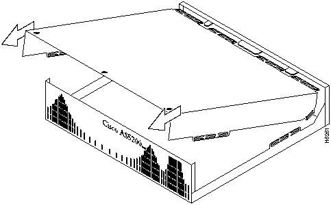
Perform the following steps to remove the chassis cover:
Figure A-3 : Removing the Chassis Cover
Figure A-4 : Lifting the Top Cover
Figure A-5 : Separating the Top Cover from the Chassis Bottom
Feature cards must be removed from the Cisco AS5200 to access the system card or to upgrade the feature cards.
You need the following tools to remove the feature cards:
Perform the following steps to remove the feature cards:
Figure A-6 : Feature Card Removal
To upgrade the boot read-only memory (ROM) software to a new software image, the existing boot ROMs must be replaced.
The following tools and equipment are required to replace the boot PROMs:
Perform the following steps to replace the boot ROMs:
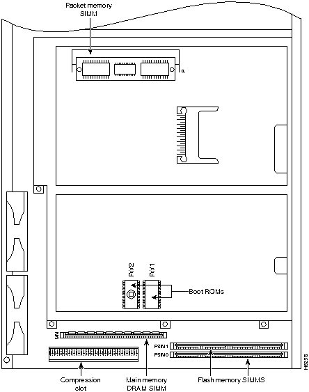
Figure A-7 : System Card Layout
This section describes how to upgrade the DRAM SIMM on the system card. You might need to upgrade the DRAM SIMM for the following reasons:
There are two areas of removable DRAM SIMM in the Cisco AS5200 (see Figure A-7). This first area is the main memory DRAM SIMM (labeled MM). Main memory is used by the CPU to store the operating configuration, routing tables, caches, and queues.
The second area is the packet memory DRAM SIMM (labeled PKT). Packet memory is used to store incoming and outgoing packets.
You need the following tools to remove and replace the DRAM SIMM on the Cisco AS5200:
Main Memory DRAM SIMM Installation
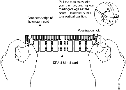
Perform the following steps to install the main memory DRAM SIMMs:
Figure A-8 : Removing and Replacing the CPU DRAM SIMM
The system code (software) is stored in Flash memory SIMMs. The 80-pin Flash memory SIMMs must be purchased from Cisco Systems, Inc. Contact a customer service representative for more information.
The system code for the Cisco AS5200 is contained on two 80-pin Flash memory SIMMs. Flash memory must be installed in both system-code SIMMs (labeled FSIM0 and FSIM1).
You need the following tools to remove and replace the system-code SIMMs on the Cisco AS5200:
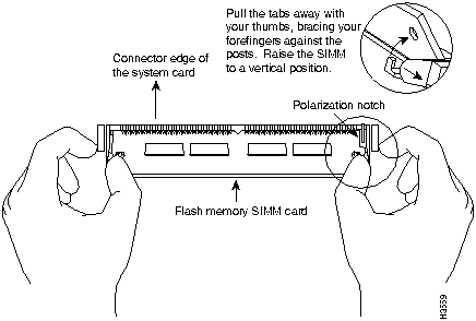
Perform the following steps to upgrade the system-code Flash memory SIMMs:
Figure A-9 : Removing and Replacing the System-Code SIMM
This section describes the procedure for closing the chassis.
You need the following tools for replacing the chassis cover:
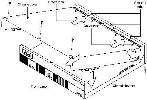
After you finish the maintenance for your system, perform the following steps to replace the cover:
Figure A-10 : Replacing the Chassis Cover
This section explains how to recover a lost password. There are three types of passwords:
To recover a lost enable password you must set the configuration register to (0x142) so that the contents of nonvolatile random--access memory (NVRAM) are ignored. This allows you to see your password. The enable secret password is encrypted and cannot be recovered; it must be replaced. The enable and virtual terminal passwords can be encrypted or clear text.
Perform the following steps to recover a lost password:
Changing the Virtual Configuration Register Settings
The Cisco AS5200 has a 16-bit virtual configuration register, which is written into NVRAM. You might want to change the virtual configuration register settings for the following reasons:
Table A-1 lists the meaning of each virtual configuration memory bit and defines the boot field names.
Table A-1 : Virtual Configuration Register Bit Meanings
Changing Configuration Register Settings
Perform the following steps to change the configuration register while running the Cisco IOS software:
Table A-2 : Explanation of Boot Field (Configuration Register Bits 00 to 03)
Virtual Configuration Register Bit Meanings
The lowest four bits of the virtual configuration register (bits 3, 2, 1, and 0) form the boot field. (See Table A-2.) The boot field specifies a number in binary form. If you set the boot field value to 0, you must boot the operating system manually by entering the b command at the bootstrap prompt, as follows:
The b command options are as follows:
If you set the boot field value to a value of 0x2 through 0xF, and a valid system boot command is stored in the configuration file, the Cisco AS5200 boots the system software as directed by that value. If you set the boot field to any other bit pattern, the Cisco AS5200 uses the resulting number to form a default boot filename for booting from the network using a TFTP server. (See Table A-3.)
Table A-3 : Default Boot Filenames
In the following example, the virtual configuration register is set to boot the Cisco AS5200 from Flash memory and to ignore Break at the next reboot of the access server:
The Cisco AS5200 creates a default boot filename as part of the automatic configuration processes. The boot filename consists of cisco, plus the octal equivalent of the boot field number, a hyphen, and the processor type.
Bit 8 controls the console Break key. Setting bit 8 (the factory default) causes the processor to ignore the console Break key. Clearing bit 8 causes the processor to interpret the Break key as a command to force the system into the bootstrap monitor, which halts normal operation. A break command can be sent in the first 60 seconds while the system reboots, regardless of the configuration settings.
Bit 10 controls the host portion of the IP broadcast address. Setting bit 10 causes the processor to use all zeros. Clearing bit 10 (the factory default) causes the processor to use all ones. Bit 10 interacts with bit 14, which controls the network and subnet portions of the broadcast address. (See Table A-4.)
Table A-4 : Configuration Register Settings for Broadcast Address Destination
Bits 11 and 12 in the configuration register determine the baud rate of the console terminal.
Table A-5 : System Console Terminal Baud Rate Settings
Bit 13 determines the Cisco AS5200 response to a bootload failure. Setting bit 13 (the factory default) causes the Cisco AS5200 to load operating software from ROM after five unsuccessful attempts to load a boot file from the network. Clearing bit 13 causes the Cisco AS5200 to continue attempting to load a boot file from the network indefinitely.
Enabling Booting from Flash Memory
To disable Break and enable the boot system flash command, enter the config-register command with the value shown in the following example:
Copying a Cisco IOS Image to Flash Memory
You might need to copy a new Cisco IOS image to Flash memory whenever a new image or maintenance release becomes available.
Perform the following steps to copy a new image to Flash memory:
Disaster Recovery Copy of a Cisco Boot Image to Boot Flash Memory
Use the following procedure to copy a Cisco boot image to boot flash if both the boot and system images have been erased from Flash memory and only the ROM monitor is available. The ROM monitor xmodem command can be used to copy a Cisco boot image from a PC. The PC can be directly connected to the Cisco AS5200 through the console port or remotely through a modem connected to the auxiliary console port.
To use this procedure, the PC must have the following files and application software:
Modem Configuration Requirements
If the PC is connected through the auxiliary console port, the modems must use the following configuration settings:
The receiving modem must also have the following configuration settings:
The following xmodem command options can be used to download the boot image:
xmodem [-cy] filename
-c Use CRC-16 mode
-y Use ymodem batch protocol mode
Perform the following steps to copy the Cisco boot image to Flash memory:
Upgrading the 12-Port Modem Firmware
You might need to copy the modem firmware to one or more modems whenever a new or maintenance release becomes available. Use the following procedure to copy the modem firmware:
![]()
![]()

![]()
![]()
![]()
![]()
![]()

![]()
![]()
![]()
![]()
![]()
rommon 1>
o/r 0x142
rommon 2>
initialize
--- System Configuration Dialog ---
Press RETURN to get started!
access server >
enable
access server #
show startup-config
enable secret 5 $1$ORPP$s9syZt4uKn3SnpuLDrhuei

enable password sand

.

.

line con 0

 password seashells
![]()
access server #
configure memory
access server #
configure terminal
access server (config)#
enable secret pail
access server (config)#
enable password shovel
access server (config)#
line con 0
access server (config-line)#
password vterm1
access server (config-line)#
interface ethernet 0
access server (config-if)#
no shutdown
access server (config-if)#
config-register 0x2102
access server (config)#
![]()
access server #
copy running-config startup-config
Building configuration...
[OK]
access server #
access server #
reload
Proceed with reload? [confirm]
![]()
Bit No.1
Hexadecimal
Meaning
00--03
0x0000--0x000F
Boot field
06
0x0040
Causes system software to ignore the contents of NVRAM (startup-config)
07
0x0080
OEM bit is enabled
08
0x0100
Break is disabled
10
0x0400
IP broadcast with all zeros
11--12
0x0800--0x1000
Console line speed
13
0x2000
Loads the boot ROM software if a Flash boot fails five times
14
0x4000
IP broadcasts do not have network numbers
15
0x8000
Enables diagnostic messages and ignores the contents of NVRAM
1 The factory-default value for the configuration register is 0x2102. This value is a combination of the following: bit 13 = 0x2000, bit 8 = 0x0100, and bits 00 through 03 = 0x0002.
access server >
enable
password:
<password>
access server #
access server #
configure terminal
access server #
config-register 0x
value
Boot Field
Boot Process
0x0
Stops the boot process in the ROM monitor.
0x1
Stops the boot process in the boot ROM monitor.
0x3--0xF
Specifies a default filename for booting over the network from a TFTP server.
Enables boot system commands that override the default filename for booting over the network from a TFTP server.
0x2
Full boot process, which loads the Cisco boot image in Boot Flash memory.
Configuration register is 0x142 (will be 0x102 at next reload)
rommon 1> b [tftp] flash filename
Action or Filename
Bit 3
Bit 2
Bit 1
Bit 0
bootstrap mode
0
0
0
0
ROM software
0
0
0
1
cisco2-as5200
0
0
1
0
cisco3-as5200
0
0
1
1
cisco4-as5200
0
1
0
0
cisco5-as5200
0
1
0
1
cisco6-as5200
0
1
1
0
cisco7-as5200
0
1
1
1
cisco10-as5200
1
0
0
0
cisco11-as5200
1
0
0
1
cisco12-as5200
1
0
1
0
cisco13-as5200
1
0
1
1
cisco14-as5200
1
1
0
0
cisco15-as5200
1
1
0
1
cisco16-as5200
1
1
1
0
cisco17-as5200
1
1
1
1
access server > enable
password: <enablepassword>
access server # conf term
Enter configuration commands, one per line.
Edit with DELETE, CTRL/W, and CTRL/U; end with CTRL/Z
config-register 0x102
boot system flash [filename]
^Z
access server #
Bit 14
Bit 10
Address (<net> <host>)
Off
Off
<ones> <ones>
Off
On
<zeros> <zeros>
On
On
<net> <zeros>
On
Off
<net> <ones>
Table A-5 shows the bit settings for the four available baud rates. (The factory-set default baud rate is 9600.)
Baud
Bit 12
Bit 11
9600
0
0
4800
0
1
1200
1
0
2400
1
1
access server > enable
Password: <enablepassword>
access server # config term
Enter configuration commands, one per line.
Edit with DELETE, CTRL/W, and CTRL/U; end with CTRL/Z
config-reg 0x2102
^Z
access server #
access server >
enable
Password: <
enablepassword>
access server #
copy tftp flash
Partition Size Used Free Bank-Size State Copy Mode
1 8192K 3562K 4629K 8192K Read/Write Direct
2 8192K 3394K 4797K 8192K Read/Write Direct
[Type ?<no> for partition directory; ? for full directory; q to abort]
Which partition? [default = 1]
System flash directory, partition 1:
File Length Name/status
1 3647600 as5200-im-l
[3647664 bytes used, 4740944 available, 8388608 total]
Address or name of remote host [255.255.255.255]?
Source file name?
Destination file name [filename]?
Accessing file 'as5200-jm-l' on your_tftpserver...
Loading as5200-jm-l from 1.1.1.1 (via Ethernet0): ! [OK]
Erase flash device before writing? [confirm]
Flash contains files. Are you sure you want to erase? [confirm]
yes
Copy 'as5200-jm-l' from server
as 'as5200-jm-l' into Flash WITH erase? [yes/no]yes
Erasing device... eeeeeeeeeeeeeeeeeeeeeeeeeeeeeeee ...erased
Loading as5200-jm-l from 1.1.1.1 (via Ethernet0): !!!!!!!!!!!!!!!!!!!!!!!!!!!!!!
!!!!!!!!!!!!!!!!!!!!!!!!!!!!!!!!!!!!!!!!!!!!!!!!!!!!!!!!!!!!!!!!!!!
!!!!!!!!!!!!!!!!!!!!!!!!!!!!!!!!!!!!!!!!!!!!!!!!!!!!!!!!!!!!!!!!!!!
!!!!!!!!!!!!!!!!!!!!!!!!!!!!!!!!!!!!!!!!!!!!!!!!!!!!!!!!!!!!!!!!!!!
!!!!!!!!!!!!!!!!!!!!!!!!!!!!!!!!!!!!!!!!!!!!!!!!!!!!!!!!!!!!!!!!!!!
!!!!!!!!!!!!!!!!!!!!!!!!!!!!!!!!!!!!!!!!!!!!!!!!!!!!!!!!!!!!!!!!!!!
!!!!!!!!!!!!!!!!!!!!!!!!!!!!!!!!!!!!!!!!!!!!!!!!!!!!!!!!!!!!!!!!!!!
!!!!!!!!!!!!!!!!!!!!!!!!!!!!!!!!!!!!!!!!!!!!!!!!!!!!!!!!!!!!!!!!!!!
!!!!!!!!!!!!!!!!!!!!!!!!!!!!!!!!!!!!!!!!!!!!!!!!!!!!!!!!!!!!!!!!!!!
!!!!!!!!!!!!!!!!!!!!!!!!!!!!!!!!!!!!!!!!!!!!!!!!!!!!!!!!!!!!!!!!!!!
!!!!!!!!!!!!!!!!!!!!!!!!!!!!!!!!!!!!!!!!!!!!!!!!!!!!!!!!!!!!!!!!!!!
!!!!!!!!!!!!!!!!!!!!!!!!!!!!!!!!!!!!!!!!!!!!!!!!!!!!!!!!!!!!!!!!!!!!!!!!
[OK - 6645904/8388608 bytes]
Verifying checksum... OK (0xB8F4)
Flash copy took 00:02:22 [hh:mm:ss]
access server(boot)#
conf terminal
Enter configuration commands, one per line. End with CNTL/Z.
access server(boot)(config)#
config-register 0x2102
access server(boot)(config)# end
access server(boot)#
reload
%SYS-5-CONFIG_I: Configured from console by consolel
System configuration has been modified. Save? [yes/no]: no
Proceed with reload? [confirm]
The system reboots using the new image in Flash memory.
rommon 1>
rommon 1>
xmodem
filename
Do not start sending program yet...
File size Checksum File name
2537948 bytes (0x26b9dc) as5200-boot-l
WARNING: All existing data in bootflash will be lost!
Invoke this application only for disaster recovery.
Do you wish to continue? [yes/no]:
Ready to receive file prog ...
Erasing flash at 0x3000000
program flash location 0x3000000
Download complete!
access server>
enable
Password: <
enablepassword>
access server #
copy tftp modem
Modem Firmware Download Modem Numbers? <
slot/modem>
Address or name of remote host [UNKNOWN]?
Source file name?
Accessing file '
filename on
Modem_Server...
Loading